Craft seamless signals for mobile communication systems with HT9200A and ATmega328
Behind the dial: Uncover the brilliance of the DTMF decoder
Published Feb 14, 2024
Click board™
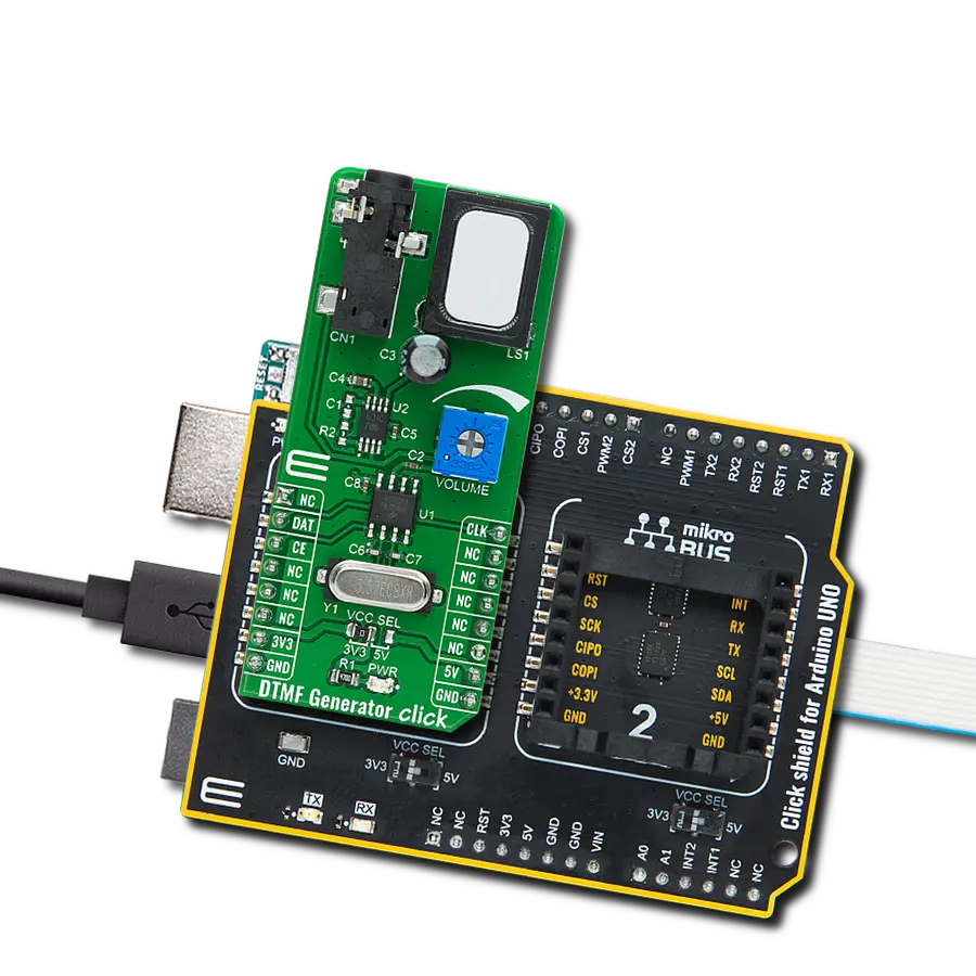
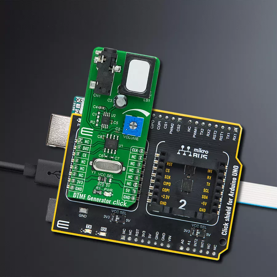
DTMF Generator Click
Dev. board
Arduino UNO Rev3
Compiler
NECTO Studio
MCU
ATmega328
Journey into the world of DTMF signal generation, where we uncover the magic that results in the creation of Dual-Tone Multi-Frequency signals vital for mobile communication systems
A
A
Hardware Overview
How does it work?
DTMF Generator Click is based on the HT9200A, a dual-tone multi-frequency decoder from Holtek Semiconductor for mobile communication systems. The HT9200A is an SMD tone generator IC designed for MCU interfaces. It can be instructed by an MCU to generate 16 dual tones and eight single tones from the DTMF pin, and it provides a Serial Mode. The system oscillator of HT9200A consists of an inverter, a bias resistor, and the required load capacitor on a chip. The oscillator function is implemented with a standard 3.579545MHz crystal connected to the X1 and X2 pins of the HT9200A. The operation of the HT9200A is based on GPIO signals fed from the mikroBUS™ to the decoder, DAT, and CLK. There is a connection between the digital codes and the tone output frequency based on the selected desired output frequency. The HT9200A employs a
data input, a 5-bit code, and a synchronous clock to transmit a DTMF signal. Every digit of a transferred number is selected by a series of combinations that consist of 5-bit data. The HT9200A will latch data on the falling edge of the CLK pin and display the output data on its output DTMF pin. Then, via a volume adjustment potentiometer, such a signal is sent to an audio amplifier, the LM386 from Texas Instruments, which represents a mono low-voltage amplifier that can be used in various applications. After the audio amplifier, the desired sound can be detected on the on-board speaker. DTMF Generator Click communicates with MCU using three GPIO pins routed on the CS, RST, and PWM pins of the mikroBUS™ socket labeled CE, DAT, and CLK. CE pin represents the Chip Enable function used to wake up the HT9200A, while DAT
and CLK pins represent data input and synchronous clock input. It also possesses an adjustable potentiometer labeled as VOLUME that adjusts the volume of that signal. It also has a 3.5mm jack output connector that allows the user to use the output DTMF signal in their projects in their way while the signal volume can still be adjusted on the VOLUME potentiometer located on the DTMF Generator Click. This Click board™ can operate with either 3.3V or 5V logic voltage levels selected via the VCC SEL jumper. This way, both 3.3V and 5V capable MCUs can use the communication lines properly. Also, this Click board™ comes equipped with a library containing easy-to-use functions and an example code that can be used as a reference for further development.


Features overview
Development board
Arduino UNO is a versatile microcontroller board built around the ATmega328P chip. It offers extensive connectivity options for various projects, featuring 14 digital input/output pins, six of which are PWM-capable, along with six analog inputs. Its core components include a 16MHz ceramic resonator, a USB connection, a power jack, an
ICSP header, and a reset button, providing everything necessary to power and program the board. The Uno is ready to go, whether connected to a computer via USB or powered by an AC-to-DC adapter or battery. As the first USB Arduino board, it serves as the benchmark for the Arduino platform, with "Uno" symbolizing its status as the
first in a series. This name choice, meaning "one" in Italian, commemorates the launch of Arduino Software (IDE) 1.0. Initially introduced alongside version 1.0 of the Arduino Software (IDE), the Uno has since become the foundational model for subsequent Arduino releases, embodying the platform's evolution.

Microcontroller Overview
MCU Card / MCU

Architecture
AVR
MCU Memory (KB)
32
Silicon Vendor
Microchip
Pin count
32
RAM (Bytes)
2048
You complete me!
Accessories
Click Shield for Arduino UNO has two proprietary mikroBUS™ sockets, allowing all the Click board™ devices to be interfaced with the Arduino UNO board without effort. The Arduino Uno, a microcontroller board based on the ATmega328P, provides an affordable and flexible way for users to try out new concepts and build prototypes with the ATmega328P microcontroller from various combinations of performance, power consumption, and features. The Arduino Uno has 14 digital input/output pins (of which six can be used as PWM outputs), six analog inputs, a 16 MHz ceramic resonator (CSTCE16M0V53-R0), a USB connection, a power jack, an ICSP header, and reset button. Most of the ATmega328P microcontroller pins are brought to the IO pins on the left and right edge of the board, which are then connected to two existing mikroBUS™ sockets. This Click Shield also has several switches that perform functions such as selecting the logic levels of analog signals on mikroBUS™ sockets and selecting logic voltage levels of the mikroBUS™ sockets themselves. Besides, the user is offered the possibility of using any Click board™ with the help of existing bidirectional level-shifting voltage translators, regardless of whether the Click board™ operates at a 3.3V or 5V logic voltage level. Once you connect the Arduino UNO board with our Click Shield for Arduino UNO, you can access hundreds of Click boards™, working with 3.3V or 5V logic voltage levels.

Used MCU Pins
mikroBUS™ mapper
Take a closer look
Click board™ Schematic

Step by step
Project assembly

Start by selecting your development board and Click board™. Begin with the Arduino UNO Rev3 as your development board.


Track your results in real time
Application Output
1. Application Output - In Debug mode, the 'Application Output' window enables real-time data monitoring, offering direct insight into execution results. Ensure proper data display by configuring the environment correctly using the provided tutorial.

2. UART Terminal - Use the UART Terminal to monitor data transmission via a USB to UART converter, allowing direct communication between the Click board™ and your development system. Configure the baud rate and other serial settings according to your project's requirements to ensure proper functionality. For step-by-step setup instructions, refer to the provided tutorial.

3. Plot Output - The Plot feature offers a powerful way to visualize real-time sensor data, enabling trend analysis, debugging, and comparison of multiple data points. To set it up correctly, follow the provided tutorial, which includes a step-by-step example of using the Plot feature to display Click board™ readings. To use the Plot feature in your code, use the function: plot(*insert_graph_name*, variable_name);. This is a general format, and it is up to the user to replace 'insert_graph_name' with the actual graph name and 'variable_name' with the parameter to be displayed.

Software Support
Library Description
This library contains API for DTMF Generator Click driver.
Key functions:
dtmfgenerator_set_dat- Set DATA ( RST ) pin state functiondtmfgenerator_power_on- Power ON functiondtmfgenerator_transmit_out_tone- The function transmit duration time of the desired tone
Open Source
Code example
The complete application code and a ready-to-use project are available through the NECTO Studio Package Manager for direct installation in the NECTO Studio. The application code can also be found on the MIKROE GitHub account.
/*!
 * @file main.c
 * @brief DTMF Generator Click Example.
 *
 * # Description
 * This is an example which demonstrates the use of DTMF Generator Click board.
 *
 * The demo application is composed of two sections :
 *
 * ## Application Init
 * Initialization driver enables - GPIO,
 * run the power-on sequence, also write log.
 *
 * ## Application Task
 * DTMF Generator Click board DTMF generator transmits the signal
 * for generating tone for digits :
 * "0", "1", "2", "3", "4", "5", "6", "7", "8", "9",
 * "A", "B", "C", "D", "*" and "#".
 * All data logs write on USB uart changes.
 *
 * @author Stefan Ilic
 *
 */

#include "board.h"
#include "log.h"
#include "dtmfgenerator.h"

static dtmfgenerator_t dtmfgenerator;   /**< DTMF Generator Click driver object. */
static log_t logger;    /**< Logger object. */

static uint16_t signal_duration = 500;

void application_init ( void ) {
    log_cfg_t log_cfg;  /**< Logger config object. */
    dtmfgenerator_cfg_t dtmfgenerator_cfg;  /**< Click config object. */

    /**
     * Logger initialization.
     * Default baud rate: 115200
     * Default log level: LOG_LEVEL_DEBUG
     * @note If USB_UART_RX and USB_UART_TX
     * are defined as HAL_PIN_NC, you will
     * need to define them manually for log to work.
     * See @b LOG_MAP_USB_UART macro definition for detailed explanation.
     */
    LOG_MAP_USB_UART( log_cfg );
    log_init( &logger, &log_cfg );
    log_info( &logger, " Application Init " );

    // Click initialization.
    dtmfgenerator_cfg_setup( &dtmfgenerator_cfg );
    DTMFGENERATOR_MAP_MIKROBUS( dtmfgenerator_cfg, MIKROBUS_1 );
    if ( DIGITAL_OUT_UNSUPPORTED_PIN == dtmfgenerator_init( &dtmfgenerator, &dtmfgenerator_cfg ) ) {
        log_error( &logger, " Application Init Error. " );
        log_info( &logger, " Please, run program again... " );

        for ( ; ; );
    }
    log_printf( &logger, " Powering on device \r\n" );
    log_printf( &logger, "--------------------\r\n" );
    dtmfgenerator_power_on( &dtmfgenerator );
    Delay_ms ( 1000 );
    log_info( &logger, " Application Task " );
}

void application_task ( void ) {
    log_printf( &logger, " TONE      '0' \r\n");
    log_printf( &logger, "---------------\r\n" );
    dtmfgenerator_transmit_out_tone( &dtmfgenerator, DTMFGENERATOR_OUT_TONE_0, signal_duration );
    dtmfgenerator_transmit_out_tone( &dtmfgenerator, DTMFGENERATOR_OUT_TONE_STOP, signal_duration );

    log_printf( &logger, " TONE      '1' \r\n");
    log_printf( &logger, "---------------\r\n" );
    dtmfgenerator_transmit_out_tone( &dtmfgenerator, DTMFGENERATOR_OUT_TONE_1, signal_duration );
    dtmfgenerator_transmit_out_tone( &dtmfgenerator, DTMFGENERATOR_OUT_TONE_STOP, signal_duration );

    log_printf( &logger, " TONE      '2' \r\n");
    log_printf( &logger, "---------------\r\n" );
    dtmfgenerator_transmit_out_tone( &dtmfgenerator, DTMFGENERATOR_OUT_TONE_2, signal_duration );
    dtmfgenerator_transmit_out_tone( &dtmfgenerator, DTMFGENERATOR_OUT_TONE_STOP, signal_duration );

    log_printf( &logger, " TONE      '3' \r\n");
    log_printf( &logger, "---------------\r\n" );
    dtmfgenerator_transmit_out_tone( &dtmfgenerator, DTMFGENERATOR_OUT_TONE_3, signal_duration );
    dtmfgenerator_transmit_out_tone( &dtmfgenerator, DTMFGENERATOR_OUT_TONE_STOP, signal_duration );

    log_printf( &logger, " TONE      '4' \r\n");
    log_printf( &logger, "---------------\r\n" );
    dtmfgenerator_transmit_out_tone( &dtmfgenerator, DTMFGENERATOR_OUT_TONE_4, signal_duration );
    dtmfgenerator_transmit_out_tone( &dtmfgenerator, DTMFGENERATOR_OUT_TONE_STOP, signal_duration );

    log_printf( &logger, " TONE      '5' \r\n");
    log_printf( &logger, "---------------\r\n" );
    dtmfgenerator_transmit_out_tone( &dtmfgenerator, DTMFGENERATOR_OUT_TONE_5, signal_duration );
    dtmfgenerator_transmit_out_tone( &dtmfgenerator, DTMFGENERATOR_OUT_TONE_STOP, signal_duration );

    log_printf( &logger, " TONE      '6' \r\n");
    log_printf( &logger, "---------------\r\n" );
    dtmfgenerator_transmit_out_tone( &dtmfgenerator, DTMFGENERATOR_OUT_TONE_6, signal_duration );
    dtmfgenerator_transmit_out_tone( &dtmfgenerator, DTMFGENERATOR_OUT_TONE_STOP, signal_duration );

    log_printf( &logger, " TONE      '7' \r\n");
    log_printf( &logger, "---------------\r\n" );
    dtmfgenerator_transmit_out_tone( &dtmfgenerator, DTMFGENERATOR_OUT_TONE_7, signal_duration );
    dtmfgenerator_transmit_out_tone( &dtmfgenerator, DTMFGENERATOR_OUT_TONE_STOP, signal_duration );

    log_printf( &logger, " TONE      '8' \r\n");
    log_printf( &logger, "---------------\r\n" );
    dtmfgenerator_transmit_out_tone( &dtmfgenerator, DTMFGENERATOR_OUT_TONE_8, signal_duration );
    dtmfgenerator_transmit_out_tone( &dtmfgenerator, DTMFGENERATOR_OUT_TONE_STOP, signal_duration );

    log_printf( &logger, " TONE      '9' \r\n");
    log_printf( &logger, "---------------\r\n" );
    dtmfgenerator_transmit_out_tone( &dtmfgenerator, DTMFGENERATOR_OUT_TONE_9, signal_duration );
    dtmfgenerator_transmit_out_tone( &dtmfgenerator, DTMFGENERATOR_OUT_TONE_STOP, signal_duration );

    log_printf( &logger, " TONE      'A' \r\n");
    log_printf( &logger, "---------------\r\n" );
    dtmfgenerator_transmit_out_tone( &dtmfgenerator, DTMFGENERATOR_OUT_TONE_A, signal_duration );
    dtmfgenerator_transmit_out_tone( &dtmfgenerator, DTMFGENERATOR_OUT_TONE_STOP, signal_duration );

    log_printf( &logger, " TONE      'B' \r\n");
    log_printf( &logger, "---------------\r\n" );
    dtmfgenerator_transmit_out_tone( &dtmfgenerator, DTMFGENERATOR_OUT_TONE_B, signal_duration );
    dtmfgenerator_transmit_out_tone( &dtmfgenerator, DTMFGENERATOR_OUT_TONE_STOP, signal_duration );

    log_printf( &logger, " TONE      'C' \r\n");
    log_printf( &logger, "---------------\r\n" );
    dtmfgenerator_transmit_out_tone( &dtmfgenerator, DTMFGENERATOR_OUT_TONE_C, signal_duration );
    dtmfgenerator_transmit_out_tone( &dtmfgenerator, DTMFGENERATOR_OUT_TONE_STOP, signal_duration );

    log_printf( &logger, " TONE      'D' \r\n");
    log_printf( &logger, "---------------\r\n" );
    dtmfgenerator_transmit_out_tone( &dtmfgenerator, DTMFGENERATOR_OUT_TONE_D, signal_duration );
    dtmfgenerator_transmit_out_tone( &dtmfgenerator, DTMFGENERATOR_OUT_TONE_STOP, signal_duration );

    log_printf( &logger, " TONE      '*' \r\n");
    log_printf( &logger, "---------------\r\n" );
    dtmfgenerator_transmit_out_tone( &dtmfgenerator, DTMFGENERATOR_OUT_TONE_ASTERISK, signal_duration );
    dtmfgenerator_transmit_out_tone( &dtmfgenerator, DTMFGENERATOR_OUT_TONE_STOP, signal_duration );

    log_printf( &logger, " TONE      '#' \r\n");
    log_printf( &logger, "---------------\r\n" );
    dtmfgenerator_transmit_out_tone( &dtmfgenerator, DTMFGENERATOR_OUT_TONE_HASH, signal_duration );
    dtmfgenerator_transmit_out_tone( &dtmfgenerator, DTMFGENERATOR_OUT_TONE_STOP, signal_duration );
 }

int main ( void )
{
    /* Do not remove this line or clock might not be set correctly. */
    #ifdef PREINIT_SUPPORTED
    preinit();
    #endif

    application_init( );

    for ( ; ; )
    {
        application_task( );
    }

    return 0;
}

// ------------------------------------------------------------------------ END
Additional Support
Resources
Category:Signal Processing