Your all-in-one solution for location and connectivity based on SIM808 and ATmega328P
GPS and GSM/GPRS unite: Your ultimate tracking solution
Published Feb 14, 2024
Click board™
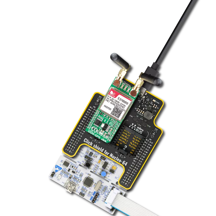
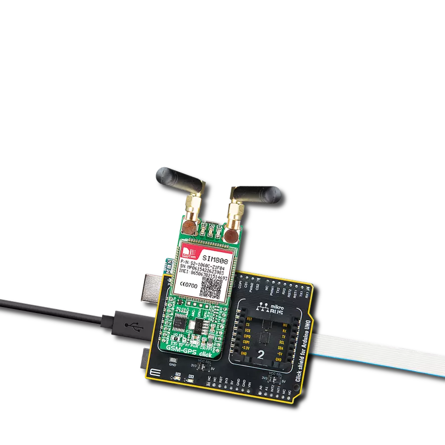
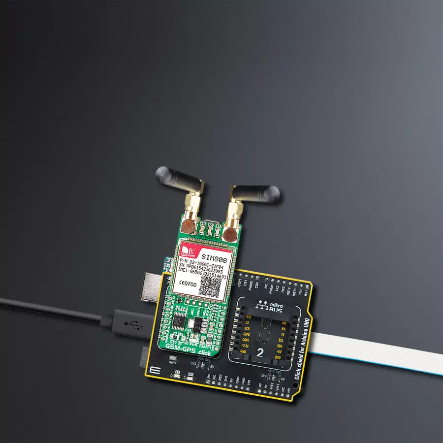
GSM-GPS Click
Dev. board
Arduino UNO Rev3
Compiler
NECTO Studio
MCU
ATmega328P
With a focus on simplifying connectivity and location tracking, we aim to empower various businesses with a single, integrated device that provides real-time GPS data alongside reliable GSM/GPRS communication capabilities
A
A
Hardware Overview
How does it work?
GSM-GPS Click is based on the SIM808, a GSM/GPRS+GPS module from SIMCom. The SIM808 is a highly integrated module and supports 0710 MUX protocol, TCP/UDP protocol, FTP/HTTP, MMS, POP3/SMTP, DTMF, jamming detection, audio record, SSL, optional Bluetooth 3.0, TTS CN, and has embedded AT. For connection with the outside world, this Click board™ features two SMA connectors for both GSM/GPRS and GPS radios, for which appropriate antennas MIKROE has in its offer for improved range and received signal strength. In addition, there is a micro-SIM slot beneath the GSM-GPS Click board and a micro-USB connector for interfacing it with a PC. The SIM808 has three operational modes. The Normal mode has several functions: GSM/GPRS Sleep, GSM Idle, GSM Talk, GPRS Standby, GPRS Data, and Charge. The SIM808 module uses these functions to transfer the data, connect between two subscribers, register to the GSM network, and more. The Power Down mode shuts down the baseband part of the module, the software is not active, and the serial port is not accessible, while the RTC remains active. In Minimum Functionality mode, the RF part of the module will not work,
the SIM card will not be accessible, or both, but the serial port will still be accessible. The AT commands set the last two operational modes. The GPRS class 12 of the SIM808 can achieve up to 85.6Kbps data rates (downlink/uplink) while using a CS-4 coding scheme. It can handle SMS via GSM/GPRS by point-to-point MO and MT, SMS cell broadcast, text, and PDU mode. There is also support for PBCCH, PP-stack, and USSD. The GPS receiver has 22 tracking and 66 acquisition channels, with a tracking sensitivity of -165dBm. The Cold Start is less sensitive with a -148dBm. The important part is TTFF, which in Hot Start is less than a second but comes in some 32s for Cold Start. The accuracy is under 2.5m CEP in a horizontal position. There are several LEDs for visual status presentation. The PPS stands for Pulse Per Second and is related to the receiver time. The TXD LED presents the network status, and the STA LED presents the power-on status. The GSM-GPS features a 4-pin header, the interface for differential audio output, and input for connecting the speaker and the microphone. The SIM808 uses the UART interface with commonly used UART RX and TX pins as its default
communication protocol for communication with the host MCU, supporting baud rates from 1200bps up to 11520bps. The UART interface also comes with the RTS (request to send) and CTS (clear to send) pins. In addition, the Click board™ features other functions accessible through mikroBUS™ signals, such as Power-on status on the STA pin (the same status as on the STA LED). The power-down of the SIM808 can be achieved by pulling LOW for 1 second the PWK pin (power key). There is a ring indicator (RI) for apparent purposes. For logic level translation, this Click board™ uses the TXB0106, a 6-bit bidirectional level-shifting and voltage translator with auto-direction sensing and ESD protection from Texas Instruments. This Click board™ can operate with either 3.3V or 5V logic voltage levels selected via the I/O SEL jumper. This way, both 3.3V and 5V capable MCUs can use the communication lines properly. However, the Click board™ comes equipped with a library containing easy-to-use functions and an example code that can be used as a reference for further development.

Features overview
Development board
Arduino UNO is a versatile microcontroller board built around the ATmega328P chip. It offers extensive connectivity options for various projects, featuring 14 digital input/output pins, six of which are PWM-capable, along with six analog inputs. Its core components include a 16MHz ceramic resonator, a USB connection, a power jack, an
ICSP header, and a reset button, providing everything necessary to power and program the board. The Uno is ready to go, whether connected to a computer via USB or powered by an AC-to-DC adapter or battery. As the first USB Arduino board, it serves as the benchmark for the Arduino platform, with "Uno" symbolizing its status as the
first in a series. This name choice, meaning "one" in Italian, commemorates the launch of Arduino Software (IDE) 1.0. Initially introduced alongside version 1.0 of the Arduino Software (IDE), the Uno has since become the foundational model for subsequent Arduino releases, embodying the platform's evolution.

Microcontroller Overview
MCU Card / MCU

Architecture
AVR
MCU Memory (KB)
32
Silicon Vendor
Microchip
Pin count
28
RAM (Bytes)
2048
You complete me!
Accessories
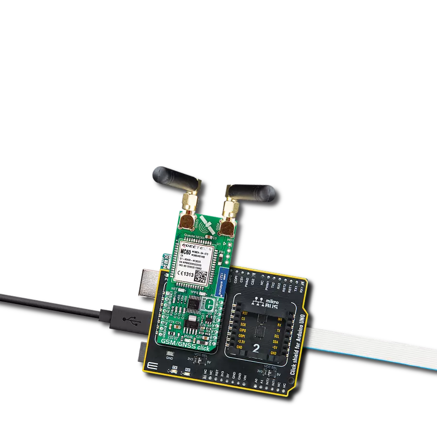
Click Shield for Arduino UNO has two proprietary mikroBUS™ sockets, allowing all the Click board™ devices to be interfaced with the Arduino UNO board without effort. The Arduino Uno, a microcontroller board based on the ATmega328P, provides an affordable and flexible way for users to try out new concepts and build prototypes with the ATmega328P microcontroller from various combinations of performance, power consumption, and features. The Arduino Uno has 14 digital input/output pins (of which six can be used as PWM outputs), six analog inputs, a 16 MHz ceramic resonator (CSTCE16M0V53-R0), a USB connection, a power jack, an ICSP header, and reset button. Most of the ATmega328P microcontroller pins are brought to the IO pins on the left and right edge of the board, which are then connected to two existing mikroBUS™ sockets. This Click Shield also has several switches that perform functions such as selecting the logic levels of analog signals on mikroBUS™ sockets and selecting logic voltage levels of the mikroBUS™ sockets themselves. Besides, the user is offered the possibility of using any Click board™ with the help of existing bidirectional level-shifting voltage translators, regardless of whether the Click board™ operates at a 3.3V or 5V logic voltage level. Once you connect the Arduino UNO board with our Click Shield for Arduino UNO, you can access hundreds of Click boards™, working with 3.3V or 5V logic voltage levels.

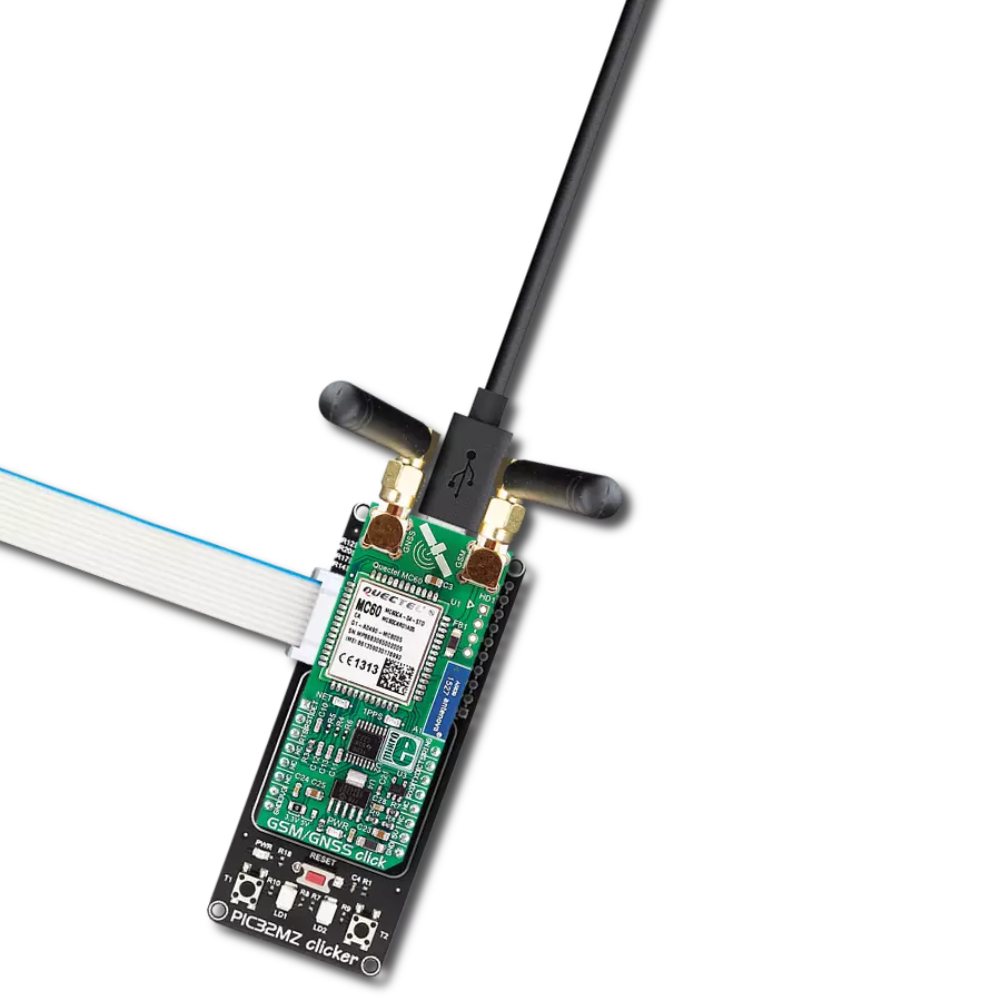
Rubber Antenna GSM/GPRS Right Angle is the perfect companion for all GSM Click boards™ in our extensive lineup. This specialized antenna is designed to optimize your wireless connectivity with impressive features. With a wide frequency range spanning 824-894/1710-1990MHz or 890-960/1710-1890MHz, it can handle various frequency bands, ensuring a seamless and reliable connection. The antenna boasts an impedance of 50 Ohms and a gain of 2dB, enhancing signal reception and transmission. Its 70/180MHz bandwidth provides flexibility for diverse applications. The vertical polarization further enhances its performance. With a maximum input power capacity of 50W, this antenna ensures robust communication even under demanding conditions. Measuring a compact 50mm in length and featuring an SMA male connector, the Rubber Antenna GSM/GPRS Right Angle is a versatile and compact solution for your wireless communication needs.

Used MCU Pins
mikroBUS™ mapper
Take a closer look
Click board™ Schematic

Step by step
Project assembly

Start by selecting your development board and Click board™. Begin with the Arduino UNO Rev3 as your development board.


Software Support
Library Description
This library contains API for GSM-GPS Click driver.
Key functions:
gsmgps_send_cmd_with_parameter- Send command function with parametergsmgps_send_sms_pdu- GSM-GPS send SMS in PDU modegsmgps_generic_parser- Generic parser function.
Open Source
Code example
The complete application code and a ready-to-use project are available through the NECTO Studio Package Manager for direct installation in the NECTO Studio. The application code can also be found on the MIKROE GitHub account.
/*!
 * \file
 * \brief Gsmgps Click example
 *
 * # Description
 * This example reads and processes data from GSM-GPS Click.
 *
 * The demo application is composed of two sections :
 *
 * ## Application Init
 * Initializes the driver and powers up the module, then sets default configuration
 * for connecting the device to network.
 *
 * ## Application Task
 * Waits for the device to connect to network, then waits for the GPS position fix. Once it get a fix,
 * it sends an SMS with GPS info to the selected phone number approximately every 40 seconds.
 *
 * ## Additional Function
 * - static void gsmgps_clear_app_buf ( void )
 * - static void gsmgps_error_check( err_t error_flag )
 * - static void gsmgps_log_app_buf ( void )
 * - static void gsmgps_check_connection( void )
 * - static err_t gsmgps_rsp_check ( void )
 * - static err_t gsmgps_process ( void )
 * - static void gps_parser_application ( void )
 *
 * @note
 * In order for the example to work, user needs to set the phone number to which he wants
 * to send an SMS, and also will need to set an APN and SMSC (required for PDU mode only) of entered SIM card.
 * Enter valid data for the following macros: SIM_APN, SIM_SMSC and PHONE_NUMBER_TO_MESSAGE.
 * E.g.
    SIM_APN "vipmobile"
    SIM_SMSC "+381610401"
    PHONE_NUMBER_TO_MESSAGE "+381659999999"
 *
 * @author MikroE Team
 *
 */
// ------------------------------------------------------------------- INCLUDES

#include "board.h"
#include "log.h"
#include "gsmgps.h"
#include "string.h"

#define APP_OK                              0
#define APP_ERROR_DRIVER                    -1
#define APP_ERROR_OVERFLOW                  -2
#define APP_ERROR_TIMEOUT                   -3

#define RSP_OK                              "OK"
#define RSP_ERROR                           "ERROR"

#define SIM_APN                             ""  // Set valid SIM APN
#define SIM_SMSC                            ""  // Set valid SMS Service Center Address - only in PDU mode
#define PHONE_NUMBER_TO_MESSAGE             "" // Set Phone number to message

#define PROCESS_BUFFER_SIZE                 256

#define WAIT_FOR_CONNECTION                 0
#define CONNECTED_TO_NETWORK                1

static gsmgps_t gsmgps;
static log_t logger;

static char app_buf[ PROCESS_BUFFER_SIZE ]  = { 0 };
static int32_t app_buf_len                  = 0;
static int32_t app_buf_cnt                  = 0;

static uint8_t app_connection_status        = WAIT_FOR_CONNECTION;

static err_t app_error_flag;
static uint8_t gps_parser_flag = 0;
static uint8_t gps_info_message[ 200 ] = { 0 };

/**
 * @brief GSM-GPS clearing application buffer.
 * @details This function clears memory of application buffer and reset its length and counter.
 * @note None.
 */
static void gsmgps_clear_app_buf ( void );

/**
 * @brief GSM-GPS data reading function.
 * @details This function reads data from device and concats data to application buffer.
 *
 * @return @li @c  0 - Read some data.
 *         @li @c -1 - Nothing is read.
 *         @li @c -2 - Application buffer overflow.
 *
 * See #err_t definition for detailed explanation.
 * @note None.
 */
static err_t gsmgps_process ( void );

/**
 * @brief GSM-GPS check for errors.
 * @details This function checks for different types of errors and logs them on UART.
 * @note None.
 */
static void gsmgps_error_check( err_t error_flag );

/**
 * @brief GSM-GPS logs application buffer.
 * @details This function logs data from application buffer.
 * @note None.
 */
static void gsmgps_log_app_buf ( void );

/**
 * @brief GSM-GPS response check.
 * @details This function checks for response and returns the status of response.
 *
 * @return application status.
 * See #err_t definition for detailed explanation.
 * @note None.
 */
static err_t gsmgps_rsp_check ( void );

/**
 * @brief GSM-GPS check connection.
 * @details This function checks connection to the network and
 *          logs that status to UART.
 *
 * @note None.
 */
static void gsmgps_check_connection( void );

/**
 * @brief GPS parser application.
 * @param rsp Response buffer.
 * @details This function logs GPS data on the USB UART and stores data in gps_info_message buffer.
 *
 * @note None.
 */
static void gps_parser_application ( char *rsp );

// ------------------------------------------------------ APPLICATION FUNCTIONS

void application_init ( void )
{
    log_cfg_t log_cfg;
    gsmgps_cfg_t cfg;

    /**
     * Logger initialization.
     * Default baud rate: 115200
     * Default log level: LOG_LEVEL_DEBUG
     * @note If USB_UART_RX and USB_UART_TX
     * are defined as HAL_PIN_NC, you will
     * need to define them manually for log to work.
     * See @b LOG_MAP_USB_UART macro definition for detailed explanation.
     */
    LOG_MAP_USB_UART( log_cfg );
    log_init( &logger, &log_cfg );
    log_info( &logger, "---- Application Init ----" );

    //  Click initialization.

    gsmgps_cfg_setup( &cfg );
    GSMGPS_MAP_MIKROBUS( cfg, MIKROBUS_1 );
    gsmgps_init( &gsmgps, &cfg );

    gsmgps_module_power( &gsmgps, GSMGPS_MODULE_POWER_ON );

    // dummy read
    gsmgps_process( );
    gsmgps_clear_app_buf( );
    // AT
    gsmgps_send_cmd( &gsmgps, GSMGPS_CMD_AT );
    app_error_flag = gsmgps_rsp_check( );
    gsmgps_error_check( app_error_flag );
    Delay_ms ( 500 );

    // ATI - product information
    gsmgps_send_cmd( &gsmgps, GSMGPS_CMD_ATI );
    app_error_flag = gsmgps_rsp_check(  );
    gsmgps_error_check( app_error_flag );
    Delay_ms ( 500 );

    // CGMR - firmware version
    gsmgps_send_cmd( &gsmgps, GSMGPS_CMD_CGMR );
    app_error_flag = gsmgps_rsp_check(  );
    gsmgps_error_check( app_error_flag );
    Delay_ms ( 500 );

    // COPS - deregister from network
    gsmgps_send_cmd_with_parameter( &gsmgps, GSMGPS_CMD_COPS, "2" );
    app_error_flag = gsmgps_rsp_check(  );
    gsmgps_error_check( app_error_flag );
    Delay_ms ( 500 );

    // CGDCONT - set sim apn
    gsmgps_set_sim_apn( &gsmgps, SIM_APN );
    app_error_flag = gsmgps_rsp_check(  );
    gsmgps_error_check( app_error_flag );
    Delay_ms ( 500 );

    // CFUN - full funtionality
    gsmgps_send_cmd_with_parameter( &gsmgps, GSMGPS_CMD_CFUN, "1" );
    app_error_flag = gsmgps_rsp_check(  );
    gsmgps_error_check( app_error_flag );
    Delay_ms ( 500 );

    // COPS - automatic mode
    gsmgps_send_cmd_with_parameter( &gsmgps, GSMGPS_CMD_COPS, "0" );
    app_error_flag = gsmgps_rsp_check(  );
    gsmgps_error_check( app_error_flag );
    Delay_ms ( 1000 );
    Delay_ms ( 1000 );

    // CREG - network registration status
    gsmgps_send_cmd_with_parameter( &gsmgps, GSMGPS_CMD_CREG, "2" );
    app_error_flag = gsmgps_rsp_check(  );
    gsmgps_error_check( app_error_flag );
    Delay_ms ( 500 );

    // CIMI - request IMSI
    gsmgps_send_cmd( &gsmgps, GSMGPS_CMD_CIMI );
    app_error_flag = gsmgps_rsp_check(  );
    gsmgps_error_check( app_error_flag );
    Delay_ms ( 500 );

    // CGNSPWR - power ON GPS
    gsmgps_send_cmd_with_parameter( &gsmgps, GSMGPS_CMD_CGNSPWR, "1" );
    app_error_flag = gsmgps_rsp_check(  );
    gsmgps_error_check( app_error_flag );
    Delay_ms ( 500 );

    app_buf_len = 0;
    app_buf_cnt = 0;
    app_connection_status = WAIT_FOR_CONNECTION;
    log_info( &logger, " Application Task " );
    Delay_ms ( 1000 );
    Delay_ms ( 1000 );
    Delay_ms ( 1000 );
    Delay_ms ( 1000 );
    Delay_ms ( 1000 );
}

void application_task ( void )
{
    if ( app_connection_status == WAIT_FOR_CONNECTION )
    {
        // CGATT - request IMSI
        gsmgps_send_cmd_check( &gsmgps, GSMGPS_CMD_CGATT );
        app_error_flag = gsmgps_rsp_check(  );
        gsmgps_error_check( app_error_flag );
        Delay_ms ( 500 );

        // CREG - network registration status
        gsmgps_send_cmd_check( &gsmgps, GSMGPS_CMD_CREG );
        app_error_flag = gsmgps_rsp_check(  );
        gsmgps_error_check( app_error_flag );
        Delay_ms ( 500 );

        // CSQ - signal quality
        gsmgps_send_cmd( &gsmgps, GSMGPS_CMD_CSQ );
        app_error_flag = gsmgps_rsp_check(  );
        gsmgps_error_check( app_error_flag );
        Delay_ms ( 1000 );
        Delay_ms ( 1000 );
        Delay_ms ( 1000 );
        Delay_ms ( 1000 );
        Delay_ms ( 1000 );
    }
    else
    {
        log_info( &logger, "CONNECTED TO NETWORK" );

        // SMS message format - PDU mode
        gsmgps_send_cmd_with_parameter( &gsmgps, GSMGPS_CMD_CMGF, "0" );
        app_error_flag = gsmgps_rsp_check(  );
        gsmgps_error_check( app_error_flag );
        Delay_ms ( 1000 );
        Delay_ms ( 1000 );
        Delay_ms ( 1000 );

        for( ; ; )
        {
            // Get GPS info
            gps_parser_flag = 1;
            gsmgps_send_cmd_with_parameter( &gsmgps, GSMGPS_CMD_CGPSINF, "2" );
            app_error_flag = gsmgps_rsp_check(  );
            gsmgps_error_check( app_error_flag );
            Delay_ms ( 1000 );
            Delay_ms ( 1000 );
            Delay_ms ( 1000 );

            if ( gps_parser_flag == 0 )
            {
                log_printf( &logger, "> Sending message to phone number...\r\n" );
                gsmgps_send_sms_pdu ( &gsmgps, SIM_SMSC, PHONE_NUMBER_TO_MESSAGE, gps_info_message );
                app_error_flag = gsmgps_rsp_check(  );
                gsmgps_error_check( app_error_flag );
                // 30 seconds delay
                Delay_ms ( 1000 );
                Delay_ms ( 1000 );
                Delay_ms ( 1000 );
                Delay_ms ( 1000 );
                Delay_ms ( 1000 );
                Delay_ms ( 1000 );
                Delay_ms ( 1000 );
                Delay_ms ( 1000 );
                Delay_ms ( 1000 );
                Delay_ms ( 1000 );
                Delay_ms ( 1000 );
                Delay_ms ( 1000 );
                Delay_ms ( 1000 );
                Delay_ms ( 1000 );
                Delay_ms ( 1000 );
                Delay_ms ( 1000 );
                Delay_ms ( 1000 );
                Delay_ms ( 1000 );
                Delay_ms ( 1000 );
                Delay_ms ( 1000 );
                Delay_ms ( 1000 );
                Delay_ms ( 1000 );
                Delay_ms ( 1000 );
                Delay_ms ( 1000 );
                Delay_ms ( 1000 );
                Delay_ms ( 1000 );
                Delay_ms ( 1000 );
                Delay_ms ( 1000 );
                Delay_ms ( 1000 );
                Delay_ms ( 1000 );
            }
        }
    }
}

int main ( void )
{
    /* Do not remove this line or clock might not be set correctly. */
    #ifdef PREINIT_SUPPORTED
    preinit();
    #endif

    application_init( );

    for ( ; ; )
    {
        application_task( );
    }

    return 0;
}

static void gsmgps_clear_app_buf ( void )
{
    memset( app_buf, 0, app_buf_len );
    app_buf_len = 0;
    app_buf_cnt = 0;
}

static err_t gsmgps_process ( void )
{
    err_t return_flag = APP_ERROR_DRIVER;
    int32_t rx_size;
    char rx_buff[ PROCESS_BUFFER_SIZE ] = { 0 };

    rx_size = gsmgps_generic_read( &gsmgps, rx_buff, PROCESS_BUFFER_SIZE );

    if ( rx_size > 0 )
    {
        int32_t buf_cnt = 0;
        return_flag = APP_OK;

        if ( app_buf_len + rx_size >= PROCESS_BUFFER_SIZE )
        {
            gsmgps_clear_app_buf(  );
            return_flag = APP_ERROR_OVERFLOW;
        }
        else
        {
            buf_cnt = app_buf_len;
            app_buf_len += rx_size;
        }

        for ( int32_t rx_cnt = 0; rx_cnt < rx_size; rx_cnt++ )
        {
            if ( rx_buff[ rx_cnt ] != 0 )
            {
                app_buf[ ( buf_cnt + rx_cnt ) ] = rx_buff[ rx_cnt ];
            }
            else
            {
                app_buf_len--;
                buf_cnt--;
            }
        }
    }

    return return_flag;
}

static err_t gsmgps_rsp_check ( void )
{
    uint16_t timeout_cnt = 0;
    uint16_t timeout = 10000;

    err_t error_flag = gsmgps_process(  );

    if ( ( error_flag != 0 ) && ( error_flag != -1 ) )
    {
        return error_flag;
    }

    while ( ( strstr( app_buf, RSP_OK ) == 0 ) && ( strstr( app_buf, RSP_ERROR ) == 0 ) )
    {
        error_flag = gsmgps_process(  );
        if ( ( error_flag != 0 ) && ( error_flag != -1 ) )
        {
            return error_flag;
        }

        timeout_cnt++;
        if ( timeout_cnt > timeout )
        {
            while ( ( strstr( app_buf, RSP_OK ) == 0 ) && ( strstr( app_buf, RSP_ERROR ) == 0 ) )
            {
                gsmgps_send_cmd( &gsmgps, GSMGPS_CMD_AT );
                gsmgps_process(  );
                Delay_ms ( 100 );
            }
            gsmgps_clear_app_buf(  );
            return APP_ERROR_TIMEOUT;
        }

        Delay_ms ( 1 );
    }

    gsmgps_check_connection();

    gsmgps_log_app_buf();

    return APP_OK;
}

static void gsmgps_error_check( err_t error_flag )
{
    if ( ( error_flag != 0 ) && ( error_flag != -1 ) )
    {
        switch ( error_flag )
        {
            case -2:
                log_error( &logger, " Overflow!" );
                break;
            case -3:
                log_error( &logger, " Timeout!" );
                break;
            default:
                break;
        }
    }
}

static void gsmgps_log_app_buf ( void )
{
    if ( gps_parser_flag == 1 )
    {
        gps_parser_application( app_buf );

    }
    else
    {
        for ( int32_t buf_cnt = 0; buf_cnt < app_buf_len; buf_cnt++ )
        {
            log_printf( &logger, "%c", app_buf[ buf_cnt ] );
        }
        log_printf( &logger, "\r\n-----------------------------------\r\n" );
    }

    gsmgps_clear_app_buf(  );
}

static void gsmgps_check_connection( void )
{
    #define CONNECTED "+CGATT: 1"

    if ( strstr( app_buf, CONNECTED ) != 0 )
    {
        app_connection_status = CONNECTED_TO_NETWORK;
    }
}

static void gps_parser_application ( char *rsp )
{
    char element_buf[ 200 ] = { 0 };
    memset( gps_info_message, 0, 200 );
    gsmgps_generic_parser( rsp, GSMGPS_NEMA_GPGGA, GSMGPS_GPGGA_LATITUDE, element_buf );
    if ( strcmp( element_buf, "0000.0000" ) != 0 )
    {
        strcpy( gps_info_message, "GSM-GPS Click - GPS info\n" );
        strcat( gps_info_message, "Latitude: " );
        strcat( gps_info_message, element_buf );
        log_printf( &logger, "Latitude:  %s\r\n", element_buf );
        gsmgps_generic_parser( rsp, GSMGPS_NEMA_GPGGA, GSMGPS_GPGGA_LONGITUDE, element_buf );
        strcat( gps_info_message, "\nLongitude: " );
        strcat( gps_info_message, element_buf );
        log_printf( &logger, "Longitude:  %s\r\n", element_buf );
        memset( element_buf, 0, sizeof( element_buf ) );
        gsmgps_generic_parser( rsp, GSMGPS_NEMA_GPGGA, GSMGPS_GPGGA_ALTITUDE, element_buf );
        strcat( gps_info_message, "\nAltitude: " );
        strcat( gps_info_message, element_buf );
        log_printf( &logger, "Altitude: %s m\r\n", element_buf );
        gps_parser_flag = 0;
    }
    else
    {
        log_printf( &logger, "Waiting for the position fix..." );
    }
    log_printf( &logger, "\r\n-----------------------------------\r\n" );
}

// ------------------------------------------------------------------------ END
Additional Support
Resources
Category:GSM+GPS