Control the movement of two DC motors or one bipolar stepper motor with DRV8834 and ATmega328P
Dual H-bridge current-control motor driver
Published Feb 14, 2024
Click board™
H-Bridge 15 Click
Dev. board
Arduino UNO Rev3
Compiler
NECTO Studio
MCU
ATmega328P
Compact and adaptable solution for managing motor-driven functions in various applications
A
A
Hardware Overview
How does it work?
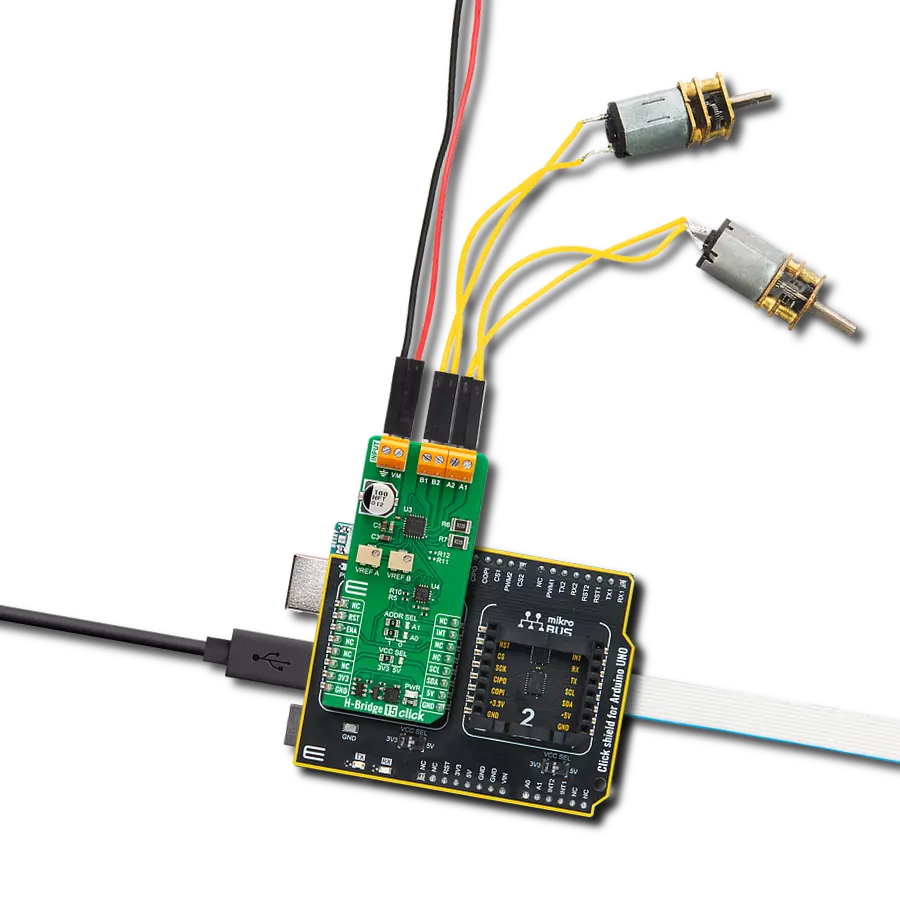
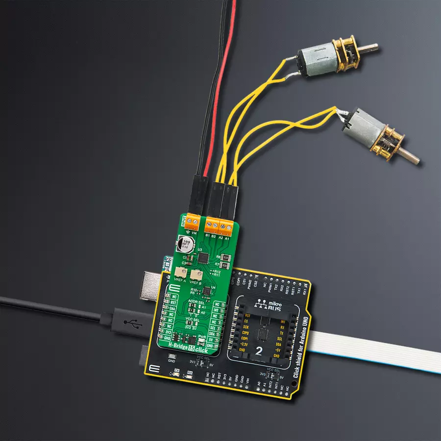
H-Bridge 15 Click is based on the DRV8834, a dual-bridge stepper or DC motor driver from Texas Instruments. The output driver block of each H-Bridge consists of N-channel power MOSFETs configured as an H-Bridge to drive the motor windings. Each H-Bridge includes circuitry to regulate or limit the winding current. There are two general control modes. The indexer logic with simple step/direction control and up to 1/32-step micro-stepping is one. The other is a phase/enable control that can drive external references for more than 1/32-step micro-stepping. The PCA9538, a low-voltage 8-bit I/O port from NXP, controls the logic states of the motor driver inputs. By setting the CONFIG input pin of the motor driver to a HIGH
state, you can select the indexer mode. Otherwise, you can select the phase/enable mode. Please note that you can drive DC motors only in phase/enable mode, while a stepper motor can be driven in any of these. The PCA9538 allows you to control the enable inputs of both bridges, micro-step modes, step inputs, direction, sleep mode, and more. It even takes the fault outputs of the motor driver. The voltage reference for both bridges is provided by the motor driver voltage reference output and two onboard potentiometers labeled VREF A and VREF B. Over those potentiometers, you can set the winding current for both bridges. The decay modes for both bridges are left for you to set over unpopulated jumper resistors. H-Bridge
15 Click uses a standard 2-wire I2C interface of the PCA9538 to allow the host MCU to control the motor driver inputs. It also notifies the host MCU if any fault condition occurs over the INT pin. The RST pin allows you to reset the PCA9538. The i2c address for this I/O port can be set over the I2C ADDR jumpers. There is also the ENA pin, which, in indexer mode, can turn all outputs on or off. This Click board™ can operate with either 3.3V or 5V logic voltage levels selected via the VCC SEL jumper. This way, both 3.3V and 5V capable MCUs can use the communication lines properly. Also, this Click board™ comes equipped with a library containing easy-to-use functions and an example code that can be used for further development.

Features overview
Development board
Arduino UNO is a versatile microcontroller board built around the ATmega328P chip. It offers extensive connectivity options for various projects, featuring 14 digital input/output pins, six of which are PWM-capable, along with six analog inputs. Its core components include a 16MHz ceramic resonator, a USB connection, a power jack, an
ICSP header, and a reset button, providing everything necessary to power and program the board. The Uno is ready to go, whether connected to a computer via USB or powered by an AC-to-DC adapter or battery. As the first USB Arduino board, it serves as the benchmark for the Arduino platform, with "Uno" symbolizing its status as the
first in a series. This name choice, meaning "one" in Italian, commemorates the launch of Arduino Software (IDE) 1.0. Initially introduced alongside version 1.0 of the Arduino Software (IDE), the Uno has since become the foundational model for subsequent Arduino releases, embodying the platform's evolution.

Microcontroller Overview
MCU Card / MCU

Architecture
AVR
MCU Memory (KB)
32
Silicon Vendor
Microchip
Pin count
28
RAM (Bytes)
2048
You complete me!
Accessories
Click Shield for Arduino UNO has two proprietary mikroBUS™ sockets, allowing all the Click board™ devices to be interfaced with the Arduino UNO board without effort. The Arduino Uno, a microcontroller board based on the ATmega328P, provides an affordable and flexible way for users to try out new concepts and build prototypes with the ATmega328P microcontroller from various combinations of performance, power consumption, and features. The Arduino Uno has 14 digital input/output pins (of which six can be used as PWM outputs), six analog inputs, a 16 MHz ceramic resonator (CSTCE16M0V53-R0), a USB connection, a power jack, an ICSP header, and reset button. Most of the ATmega328P microcontroller pins are brought to the IO pins on the left and right edge of the board, which are then connected to two existing mikroBUS™ sockets. This Click Shield also has several switches that perform functions such as selecting the logic levels of analog signals on mikroBUS™ sockets and selecting logic voltage levels of the mikroBUS™ sockets themselves. Besides, the user is offered the possibility of using any Click board™ with the help of existing bidirectional level-shifting voltage translators, regardless of whether the Click board™ operates at a 3.3V or 5V logic voltage level. Once you connect the Arduino UNO board with our Click Shield for Arduino UNO, you can access hundreds of Click boards™, working with 3.3V or 5V logic voltage levels.

DC Gear Motor - 430RPM (3-6V) represents an all-in-one combination of a motor and gearbox, where the addition of gear leads to a reduction of motor speed while increasing the torque output. This gear motor has a spur gearbox, making it a highly reliable solution for applications with lower torque and speed requirements. The most critical parameters for gear motors are speed, torque, and efficiency, which are, in this case, 520RPM with no load and 430RPM at maximum efficiency, alongside a current of 60mA and a torque of 50g.cm. Rated for a 3-6V operational voltage range and clockwise/counterclockwise rotation direction, this motor represents an excellent solution for many functions initially performed by brushed DC motors in robotics, medical equipment, electric door locks, and much more.

The 28BYJ-48 is an adaptable 5VDC stepper motor with a compact design, ideal for various applications. It features four phases, a speed variation ratio of 1/64, and a stride angle of 5.625°/64 steps, allowing precise control. The motor operates at a frequency of 100Hz and has a DC resistance of 50Ω ±7% at 25°C. It boasts an idle in-traction frequency greater than 600Hz and an idle out-traction frequency exceeding 1000Hz, ensuring reliability in different scenarios. With a self-positioning torque and in-traction torque both exceeding 34.3mN.m at 120Hz, the 28BYJ-48 offers robust performance. Its friction torque ranges from 600 to 1200 gf.cm, while the pull-in torque is 300 gf.cm. This motor makes a reliable and efficient choice for your stepper motor needs.

Used MCU Pins
mikroBUS™ mapper
Take a closer look
Click board™ Schematic

Step by step
Project assembly

Start by selecting your development board and Click board™. Begin with the Arduino UNO Rev3 as your development board.


Track your results in real time
Application Output
1. Application Output - In Debug mode, the 'Application Output' window enables real-time data monitoring, offering direct insight into execution results. Ensure proper data display by configuring the environment correctly using the provided tutorial.

2. UART Terminal - Use the UART Terminal to monitor data transmission via a USB to UART converter, allowing direct communication between the Click board™ and your development system. Configure the baud rate and other serial settings according to your project's requirements to ensure proper functionality. For step-by-step setup instructions, refer to the provided tutorial.

3. Plot Output - The Plot feature offers a powerful way to visualize real-time sensor data, enabling trend analysis, debugging, and comparison of multiple data points. To set it up correctly, follow the provided tutorial, which includes a step-by-step example of using the Plot feature to display Click board™ readings. To use the Plot feature in your code, use the function: plot(*insert_graph_name*, variable_name);. This is a general format, and it is up to the user to replace 'insert_graph_name' with the actual graph name and 'variable_name' with the parameter to be displayed.

Software Support
Library Description
This library contains API for H-Bridge 15 Click driver.
Key functions:
hbridge15_set_pins- H-Bridge 15 set pins function.hbridge15_set_sleep- H-Bridge 15 set sleep function.hbridge15_set_out_state- H-Bridge 15 set output function.
Open Source
Code example
The complete application code and a ready-to-use project are available through the NECTO Studio Package Manager for direct installation in the NECTO Studio. The application code can also be found on the MIKROE GitHub account.
/*!
 * @file main.c
 * @brief H-Bridge 15 Click example
 *
 * # Description
 * This example demonstrates the use of the H-Bridge 15 Click board by
 * driving the motor in both directions with braking and freewheeling.
 *
 * The demo application is composed of two sections :
 *
 * ## Application Init
 * Initializes the driver and performs the Click default configuration.
 *
 * ## Application Task
 * This example is driving a motor in both directions with
 * motor braking and freewheeling in between.
 *
 * @author Stefan Ilic
 *
 */

#include "board.h"
#include "log.h"
#include "hbridge15.h"

static hbridge15_t hbridge15;
static log_t logger;

void application_init ( void )
{
    log_cfg_t log_cfg;  /**< Logger config object. */
    hbridge15_cfg_t hbridge15_cfg;  /**< Click config object. */

    /**
     * Logger initialization.
     * Default baud rate: 115200
     * Default log level: LOG_LEVEL_DEBUG
     * @note If USB_UART_RX and USB_UART_TX
     * are defined as HAL_PIN_NC, you will
     * need to define them manually for log to work.
     * See @b LOG_MAP_USB_UART macro definition for detailed explanation.
     */
    LOG_MAP_USB_UART( log_cfg );
    log_init( &logger, &log_cfg );
    log_info( &logger, " Application Init " );

    // Click initialization.
    hbridge15_cfg_setup( &hbridge15_cfg );
    HBRIDGE15_MAP_MIKROBUS( hbridge15_cfg, MIKROBUS_1 );
    if ( I2C_MASTER_ERROR == hbridge15_init( &hbridge15, &hbridge15_cfg ) )
    {
        log_error( &logger, " Communication init." );
        for ( ; ; );
    }

    if ( HBRIDGE15_ERROR == hbridge15_default_cfg ( &hbridge15 ) )
    {
        log_error( &logger, " Default configuration." );
        for ( ; ; );
    }

    log_info( &logger, " Application Task " );
}

void application_task ( void )
{
    log_printf( &logger, " Motor in forward mode. \r\n" );
    hbridge15_set_out_state( &hbridge15, HBRIDGE15_DRIVE_MOTOR_FORWARD );
    Delay_ms ( 1000 );
    Delay_ms ( 1000 );
    Delay_ms ( 1000 );
    Delay_ms ( 1000 );
    Delay_ms ( 1000 );

    log_printf( &logger, " Motor brake is on \r\n" );
    hbridge15_set_out_state( &hbridge15, HBRIDGE15_DRIVE_MOTOR_BRAKE );
    Delay_ms ( 1000 );
    Delay_ms ( 1000 );

    log_printf( &logger, " Motor in reverse mode. \r\n" );
    hbridge15_set_out_state( &hbridge15, HBRIDGE15_DRIVE_MOTOR_REVERSE );
    Delay_ms ( 1000 );
    Delay_ms ( 1000 );
    Delay_ms ( 1000 );
    Delay_ms ( 1000 );
    Delay_ms ( 1000 );

    log_printf( &logger, " Motor is coasting \r\n" );
    hbridge15_set_out_state( &hbridge15, HBRIDGE15_DRIVE_MOTOR_FREEWHEEL );
    Delay_ms ( 1000 );
    Delay_ms ( 1000 );
}

int main ( void )
{
    /* Do not remove this line or clock might not be set correctly. */
    #ifdef PREINIT_SUPPORTED
    preinit();
    #endif

    application_init( );

    for ( ; ; )
    {
        application_task( );
    }

    return 0;
}

// ------------------------------------------------------------------------ END
Additional Support
Resources
Category:Brushed


