Experience secure and efficient remote control with Si4356 and ATmega328P
Unleash connectivity at a distance: Sub-GHz ISM RF receiver is here!

Published Feb 14, 2024
Click board™
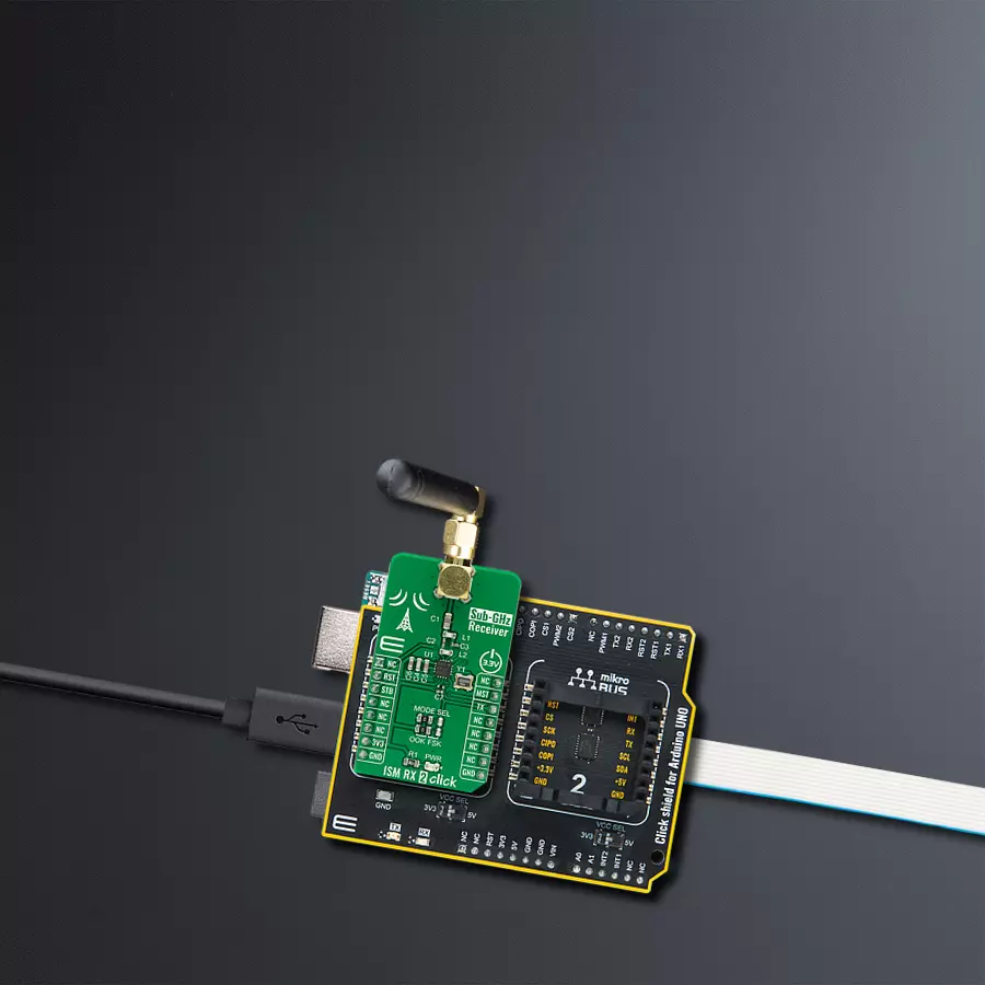
ISM RX 2 Click
Dev. board
Arduino UNO Rev3
Compiler
NECTO Studio
MCU
ATmega328P
Seamlessly integrate our sub-GHz ISM RF receiver into your home automation, industrial control, and remote access systems for long-range, low-speed communication that's robust, reliable, and ready to transform your applications.
A
A
Hardware Overview
How does it work?
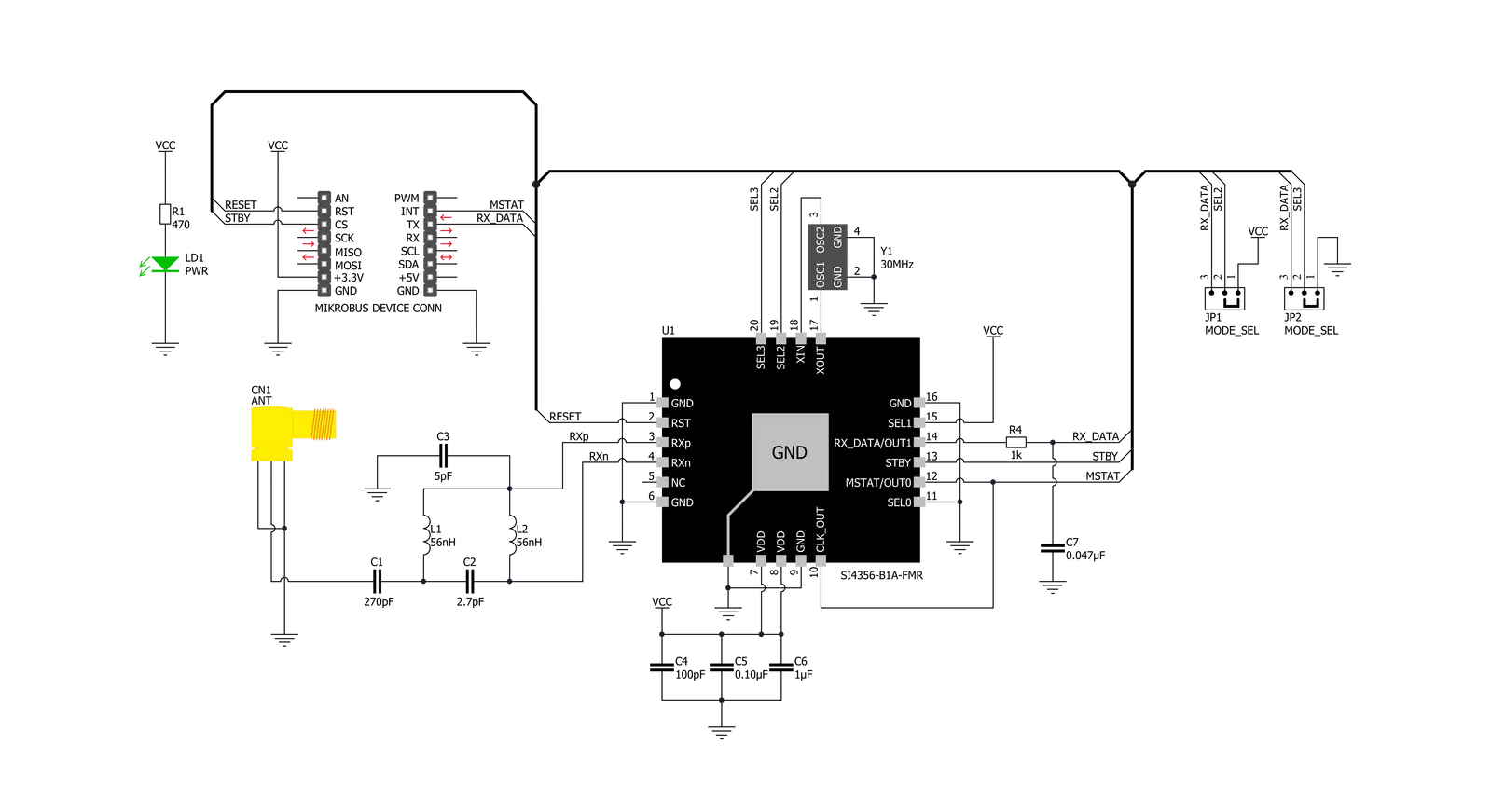
ISM RX 2 Click is based on the Si4356, an easy-to-use, size-efficient, low-current wireless receiver IC from Silicon Labs that covers the sub-GHz bands. The wide operating voltage range and low current consumption make the Si4356 an ideal solution for battery-powered applications. It has an integrated crystal oscillator and uses a single-conversion mixer to downconvert the (G)FSK, or OOK modulated receive signal to a low IF frequency. The receiver demodulates the incoming data asynchronously by oversampling the incoming transmission, and the resulting demodulated signal is sent to the system MCU via the UART interface. The Si4356 has a frequency range from 315 up to 917MHz and can be configured for operation using the four selector pins (SEL0 – SEL3) where the state of each of these pins is read internally at Start-Up and used to determine which pre-loaded configuration should be
used. The SEL0 and SEL1 pins are used to adjust the frequency, and they are connected in such a way that the frequency of this Click board™ is fixed to 434.15MHz, while the setting of the SEL2 and SEL3 pins can be changed by using the SMD jumpers labeled as MODE SEL used to select the desired modulation (G)FSK or OOK. Additionally, this Click board™ has a low-pass RC filter on the receiver data output pin, which is used to filter the output and improve sensitivity. This Click board™ communicates with MCU using the UART interface for the data transfer, while the GPIO pins on the mikroBUS™ are used for mode selection and indication. More precisely, only one UART pin from the mikroBUS™ (RX) receives the data. The Si4356 provides two operating modes: a Receive Mode and a Stand-by Mode. The operating mode can be changed by toggling the STBY signal routed to the CS pin on the mikroBUS™,
while the MSTAT signal routed to the INT pin on the mikroBUS™ represents an interrupt and indicates the current operating mode of the device. It is also possible to reset the device using an RST pin routed to the RST pin on the mikroBUS™. ISM RX 2 Click possesses the SMA antenna connector with an impedance of 50Ω, and it can be used for connecting the appropriate antenna that MikroE has in its offer for improved range and received signal strength. This Click board™ can be operated only with a 3.3V logic voltage level. The board must perform appropriate logic voltage level conversion before using MCUs with different logic levels. Also, it comes equipped with a library containing functions and an example code that can be used as a reference for further development.

Features overview
Development board
Arduino UNO is a versatile microcontroller board built around the ATmega328P chip. It offers extensive connectivity options for various projects, featuring 14 digital input/output pins, six of which are PWM-capable, along with six analog inputs. Its core components include a 16MHz ceramic resonator, a USB connection, a power jack, an
ICSP header, and a reset button, providing everything necessary to power and program the board. The Uno is ready to go, whether connected to a computer via USB or powered by an AC-to-DC adapter or battery. As the first USB Arduino board, it serves as the benchmark for the Arduino platform, with "Uno" symbolizing its status as the
first in a series. This name choice, meaning "one" in Italian, commemorates the launch of Arduino Software (IDE) 1.0. Initially introduced alongside version 1.0 of the Arduino Software (IDE), the Uno has since become the foundational model for subsequent Arduino releases, embodying the platform's evolution.

Microcontroller Overview
MCU Card / MCU

Architecture
AVR
MCU Memory (KB)
32
Silicon Vendor
Microchip
Pin count
28
RAM (Bytes)
2048
You complete me!
Accessories
Click Shield for Arduino UNO has two proprietary mikroBUS™ sockets, allowing all the Click board™ devices to be interfaced with the Arduino UNO board without effort. The Arduino Uno, a microcontroller board based on the ATmega328P, provides an affordable and flexible way for users to try out new concepts and build prototypes with the ATmega328P microcontroller from various combinations of performance, power consumption, and features. The Arduino Uno has 14 digital input/output pins (of which six can be used as PWM outputs), six analog inputs, a 16 MHz ceramic resonator (CSTCE16M0V53-R0), a USB connection, a power jack, an ICSP header, and reset button. Most of the ATmega328P microcontroller pins are brought to the IO pins on the left and right edge of the board, which are then connected to two existing mikroBUS™ sockets. This Click Shield also has several switches that perform functions such as selecting the logic levels of analog signals on mikroBUS™ sockets and selecting logic voltage levels of the mikroBUS™ sockets themselves. Besides, the user is offered the possibility of using any Click board™ with the help of existing bidirectional level-shifting voltage translators, regardless of whether the Click board™ operates at a 3.3V or 5V logic voltage level. Once you connect the Arduino UNO board with our Click Shield for Arduino UNO, you can access hundreds of Click boards™, working with 3.3V or 5V logic voltage levels.

Right angle 433MHz rubber antenna boasts a frequency range of 433MHz, ensuring optimal performance within this spectrum. With a 50Ohm impedance, it facilitates efficient signal transmission. The antenna's vertical polarization enhances signal reception in a specific orientation. Featuring a 1.5dB gain, it can improve signal strength to some extent. The antenna can handle a maximum input power of 50W, making it suitable for various applications. Its compact 50mm length minimizes spatial requirements. Equipped with an SMA male connector, it easily interfaces with compatible devices. This antenna is an adaptable solution for wireless communication needs, particularly when vertical polarization is crucial.

Used MCU Pins
mikroBUS™ mapper
Take a closer look
Click board™ Schematic
Step by step
Project assembly

Start by selecting your development board and Click board™. Begin with the Arduino UNO Rev3 as your development board.


Software Support
Library Description
This library contains API for ISM RX 2 Click driver.
Key functions:
ismrx2_get_data_pin_state- ISM RX 2 get state of DATA pin function.ismrx2_read_manchester_data- ISM RX 2 read manchester encoded data function.ismrx2_read_rf_data- ISM RX 2 read data function.
Open Source
Code example
The complete application code and a ready-to-use project are available through the NECTO Studio Package Manager for direct installation in the NECTO Studio. The application code can also be found on the MIKROE GitHub account.
/*!
* @file main.c
* @brief ISM RX 2 Click Example.
*
* # Description
* This application shows capability of ISM RX 2 Click board.
*
* The demo application is composed of two sections :
*
* ## Application Init
* Initialize GPIO pins and LOG module and sets default configuration.
*
* ## Application Task
* Wait for the data pin to go down and start sampling and wait for sync word if it's received
* collect data to buffer till it receives 0 byte
*
* @note
* Application task is broken down into two parts:
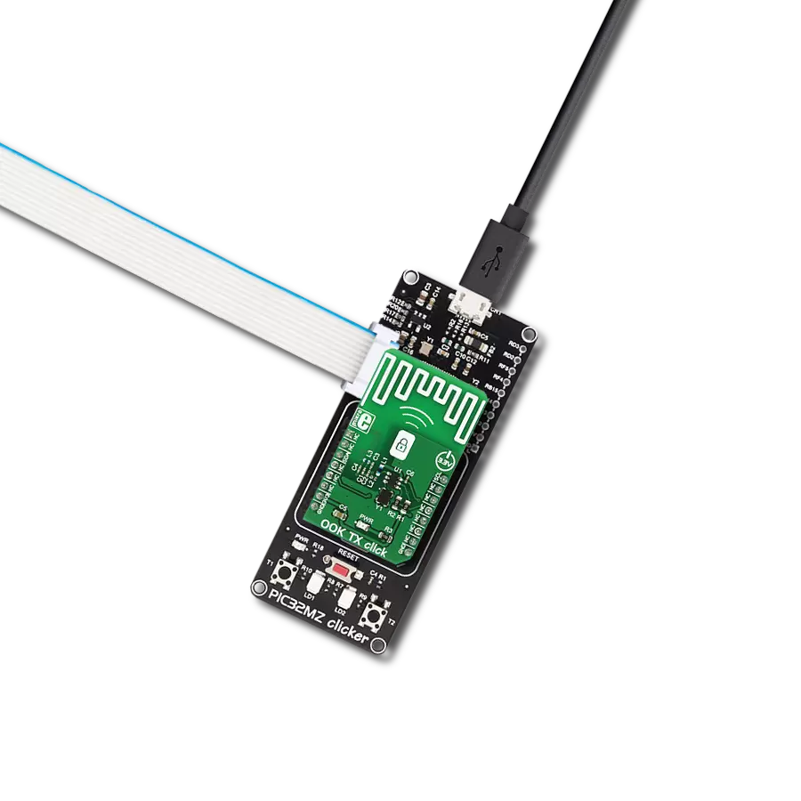
* DEFAULT_EXAMPLE - Collects data from the OOK TX Click board and displays it on the
* USB UART terminal.
* MANCHESTER_EXAMPLE - Collects Manchester encoded data from the ISM TX Click board,
* decodes it and displays it on the USB UART terminal.
*
* @author Stefan Ilic
*
*/
#include "board.h"
#include "log.h"
#include "ismrx2.h"
#define DEFAULT_EXAMPLE
// #define MANCHESTER_EXAMPLE
static ismrx2_t ismrx2; /**< ISM RX 2 Click driver object. */
static log_t logger; /**< Logger object. */
static uint8_t read_data[ 8 ] = { 0 }; /**< Read data buffer. */
void application_init ( void )
{
log_cfg_t log_cfg; /**< Logger config object. */
ismrx2_cfg_t ismrx2_cfg; /**< Click config object. */
/**
* Logger initialization.
* Default baud rate: 115200
* Default log level: LOG_LEVEL_DEBUG
* @note If USB_UART_RX and USB_UART_TX
* are defined as HAL_PIN_NC, you will
* need to define them manually for log to work.
* See @b LOG_MAP_USB_UART macro definition for detailed explanation.
*/
LOG_MAP_USB_UART( log_cfg );
log_init( &logger, &log_cfg );
log_info( &logger, " Application Init " );
// Click initialization.
ismrx2_cfg_setup( &ismrx2_cfg );
ISMRX2_MAP_MIKROBUS( ismrx2_cfg, MIKROBUS_1 );
if ( DIGITAL_OUT_UNSUPPORTED_PIN == ismrx2_init( &ismrx2, &ismrx2_cfg ) )
{
log_error( &logger, " Communication init." );
for ( ; ; );
}
if ( ISMRX2_ERROR == ismrx2_default_cfg ( &ismrx2 ) )
{
log_error( &logger, " Default configuration." );
for ( ; ; );
}
log_info( &logger, " Application Task " );
}
void application_task ( void )
{
#ifdef DEFAULT_EXAMPLE
if ( ISMRX2_PIN_STATE_LOW == ismrx2_get_data_pin_state( &ismrx2 ) )
{
if ( ISMRX2_OK == ismrx2_read_rf_data( &ismrx2, read_data ) )
{
log_printf( &logger, " RX data: " );
for ( uint8_t n_cnt = 0; n_cnt < strlen( read_data ); n_cnt++ )
{
if ( read_data[ n_cnt ] != '\0' )
{
log_printf( &logger, "%c", read_data[ n_cnt ] );
}
}
log_printf( &logger, "\r\n*********************\r\n" );
Delay_ms ( 10 );
}
}
#endif
#ifdef MANCHESTER_EXAMPLE
if ( ISMRX2_PIN_STATE_LOW == ismrx2_get_data_pin_state( &ismrx2 ) )
{
if ( ISMRX2_OK == ismrx2_read_manchester_data( &ismrx2, &read_data ) )
{
log_printf( &logger, " Read data: " );
for ( uint8_t n_cnt = 1; n_cnt < strlen( read_data ); n_cnt++ )
{
log_printf( &logger, "%c", read_data[ n_cnt ] );
}
log_printf( &logger, "\r\n*********************\r\n" );
Delay_ms ( 10 );
}
}
#endif
}
int main ( void )
{
/* Do not remove this line or clock might not be set correctly. */
#ifdef PREINIT_SUPPORTED
preinit();
#endif
application_init( );
for ( ; ; )
{
application_task( );
}
return 0;
}
// ------------------------------------------------------------------------ END
Additional Support
Resources
Category:Sub-1 GHz Transceievers