Improve your audio experience with KT403A and ATmega328P
Your favorite tunes, just a click away
Published Feb 14, 2024
Click board™
MP3 2 Click
Dev. board
Arduino UNO Rev3
Compiler
NECTO Studio
MCU
ATmega328P
Our cutting-edge MP3 solution empowers you to immerse yourself in the world of music with unparalleled clarity and convenience. It's your ultimate companion for enjoying your favorite tunes anytime, anywhere.
A
A
Hardware Overview
How does it work?
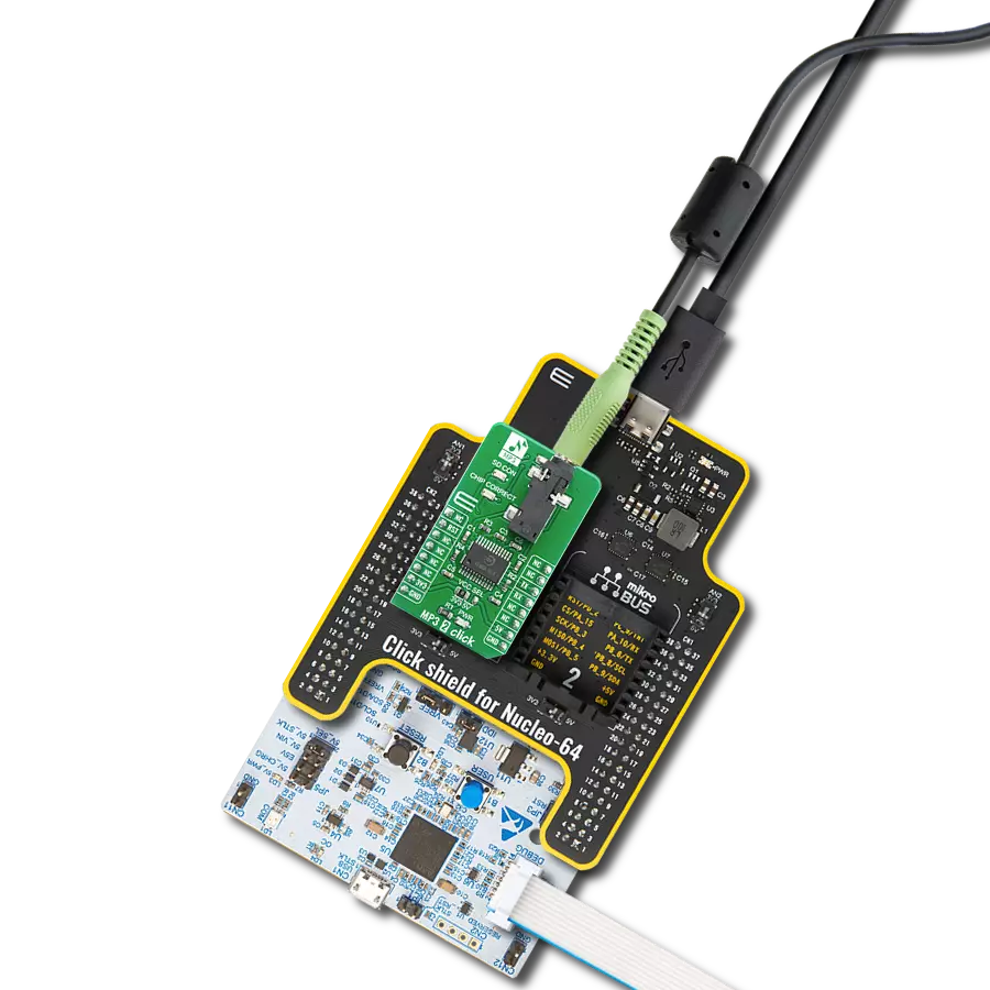
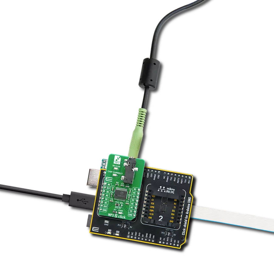
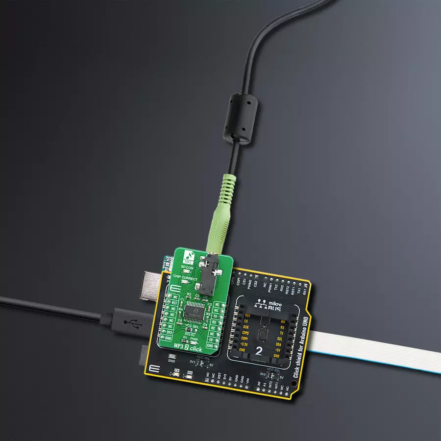
MP3 2 Click is based on the KT403A, a SOC chip solution with intergraded MCU, hardware audio MP3/WAV decoder and DSP, from Shenzhen Qianle Microelectronics Technology, as a main integrated circuit, micro SD card connector, and 3.5mm Audio Jack connector. Basically, it is a complete solution for a DAP (digital audio player) on a Click board, which can be controlled over the UART communication interface, using RX and TX pins of the mikroBUS™ socket. The default baud rate is 9600bps and it is customizable. On the MP3 2 Click, KT403A serves as a brain. It is complete SOC, which integrates16-bit MCU, audio decoder, and a 24-bit DSP. It also integrates the complete SD card interface and therefore, this click board
contains the connector onboard for an external micro SD card. Thanks to that, the user can insert a fair amount of memory if the long, continuous playback time is needed. MP3 2 Click has two status indication LEDs, onboard. The first one is named “SD Card” and it serves as an indication that the SD Card is present in the slot. The other one is “Chip Correct” and it indicates that the SD Card is correct and that the communication between the KT403A and the SD Card sucseeded. Besides the indicatora, there is one 3.5mm headphone jack onboard, so that MP3 2 Click can be connected directly to the next stage of the music playback system, ie. audio amplifier. Using the predefined command set, MP3 2 Click can be
fully controlled. One can Play/Pause a song, play a specific track, change a Volume Up and Volume Down between 0% and 100%, play the next or the previous song, repeat the current song, and more. Besides that, several sound effects are also supported, mentioned for different types of music: Normal, Jazz, Classic, Pop, and Rock. This Click board™ can operate with either 3.3V or 5V logic voltage levels selected via the VCC SEL jumper. This way, both 3.3V and 5V capable MCUs can use the communication lines properly. Also, this Click board™ comes equipped with a library containing easy-to-use functions and an example code that can be used as a reference for further development.

Features overview
Development board
Arduino UNO is a versatile microcontroller board built around the ATmega328P chip. It offers extensive connectivity options for various projects, featuring 14 digital input/output pins, six of which are PWM-capable, along with six analog inputs. Its core components include a 16MHz ceramic resonator, a USB connection, a power jack, an
ICSP header, and a reset button, providing everything necessary to power and program the board. The Uno is ready to go, whether connected to a computer via USB or powered by an AC-to-DC adapter or battery. As the first USB Arduino board, it serves as the benchmark for the Arduino platform, with "Uno" symbolizing its status as the
first in a series. This name choice, meaning "one" in Italian, commemorates the launch of Arduino Software (IDE) 1.0. Initially introduced alongside version 1.0 of the Arduino Software (IDE), the Uno has since become the foundational model for subsequent Arduino releases, embodying the platform's evolution.

Microcontroller Overview
MCU Card / MCU

Architecture
AVR
MCU Memory (KB)
32
Silicon Vendor
Microchip
Pin count
28
RAM (Bytes)
2048
You complete me!
Accessories
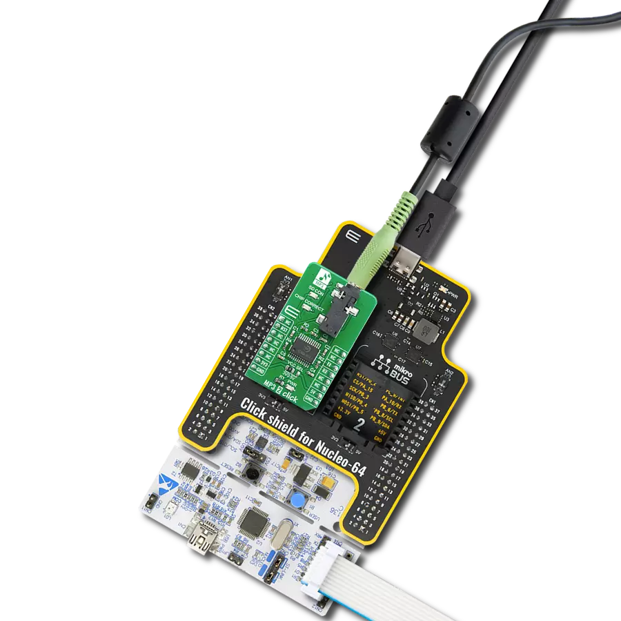
Click Shield for Arduino UNO has two proprietary mikroBUS™ sockets, allowing all the Click board™ devices to be interfaced with the Arduino UNO board without effort. The Arduino Uno, a microcontroller board based on the ATmega328P, provides an affordable and flexible way for users to try out new concepts and build prototypes with the ATmega328P microcontroller from various combinations of performance, power consumption, and features. The Arduino Uno has 14 digital input/output pins (of which six can be used as PWM outputs), six analog inputs, a 16 MHz ceramic resonator (CSTCE16M0V53-R0), a USB connection, a power jack, an ICSP header, and reset button. Most of the ATmega328P microcontroller pins are brought to the IO pins on the left and right edge of the board, which are then connected to two existing mikroBUS™ sockets. This Click Shield also has several switches that perform functions such as selecting the logic levels of analog signals on mikroBUS™ sockets and selecting logic voltage levels of the mikroBUS™ sockets themselves. Besides, the user is offered the possibility of using any Click board™ with the help of existing bidirectional level-shifting voltage translators, regardless of whether the Click board™ operates at a 3.3V or 5V logic voltage level. Once you connect the Arduino UNO board with our Click Shield for Arduino UNO, you can access hundreds of Click boards™, working with 3.3V or 5V logic voltage levels.

Used MCU Pins
mikroBUS™ mapper
Take a closer look
Click board™ Schematic

Step by step
Project assembly

Start by selecting your development board and Click board™. Begin with the Arduino UNO Rev3 as your development board.


Track your results in real time
Application Output
1. Application Output - In Debug mode, the 'Application Output' window enables real-time data monitoring, offering direct insight into execution results. Ensure proper data display by configuring the environment correctly using the provided tutorial.

2. UART Terminal - Use the UART Terminal to monitor data transmission via a USB to UART converter, allowing direct communication between the Click board™ and your development system. Configure the baud rate and other serial settings according to your project's requirements to ensure proper functionality. For step-by-step setup instructions, refer to the provided tutorial.

3. Plot Output - The Plot feature offers a powerful way to visualize real-time sensor data, enabling trend analysis, debugging, and comparison of multiple data points. To set it up correctly, follow the provided tutorial, which includes a step-by-step example of using the Plot feature to display Click board™ readings. To use the Plot feature in your code, use the function: plot(*insert_graph_name*, variable_name);. This is a general format, and it is up to the user to replace 'insert_graph_name' with the actual graph name and 'variable_name' with the parameter to be displayed.

Software Support
Library Description
This library contains API for MP3 2 Click driver.
Key functions:
mp32_hw_reset- Reset the device functionmp32_rx_cmd- Received response data functionmp32_tx_cmd- Write command function.
Open Source
Code example
The complete application code and a ready-to-use project are available through the NECTO Studio Package Manager for direct installation in the NECTO Studio. The application code can also be found on the MIKROE GitHub account.
/*!
 * \file
 * \brief Mp32 Click example
 *
 * # Description
 * This example demonstates the use of MP3 2 Click board.
 *
 * The demo application is composed of two sections :
 *
 * ## Application Init
 * Initializes the driver and enables the Click board.
 * Then sets the device to play songs from SD Card, and after that sets volume, and equalizer.
 *
 * ## Application Task
 * Demonstrates the use of play, play next, and pause modes.
 * Each step will be logged on the USB UART where you can track the program flow.
 *
 * @note
 * A valid microSD Card that contains at least one mp3 sound on it needs to be
 * inserted into the Click board.
 *
 * \author MikroE Team
 *
 */
// ------------------------------------------------------------------- INCLUDES

#include "board.h"
#include "log.h"
#include "mp32.h"
#include "string.h"

// ------------------------------------------------------------------ VARIABLES

static mp32_t mp32;
static log_t logger;

// ------------------------------------------------------ APPLICATION FUNCTIONS

void application_init ( void )
{
    log_cfg_t log_cfg;
    mp32_cfg_t cfg;

    /**
     * Logger initialization.
     * Default baud rate: 115200
     * Default log level: LOG_LEVEL_DEBUG
     * @note If USB_UART_RX and USB_UART_TX
     * are defined as HAL_PIN_NC, you will
     * need to define them manually for log to work.
     * See @b LOG_MAP_USB_UART macro definition for detailed explanation.
     */
    LOG_MAP_USB_UART( log_cfg );
    log_init( &logger, &log_cfg );
    log_info( &logger, "---- Application Init ----" );

    //  Click initialization.

    mp32_cfg_setup( &cfg );
    MP32_MAP_MIKROBUS( cfg, MIKROBUS_1 );
    mp32_init( &mp32, &cfg );

    Delay_ms ( 500 );

    log_printf( &logger, "-------------------------\r\n" );
    log_printf( &logger, "       MP3 2 Click       \r\n" );
    log_printf( &logger, "-------------------------\r\n" );
    Delay_100ms( );

    mp32_hw_reset( &mp32 );
    Delay_ms ( 100 );

    mp32_set_device( &mp32, MP32_SDCARD );
    mp32_set_volume( &mp32, 50 );
    mp32_set_eq( &mp32, MP32_EQ_NORMAL );
    Delay_ms ( 100 );
}

void application_task ( void )
{
    log_printf( &logger, " >>> Play\r\n" );
    mp32_play_mode( &mp32 );
    // 10 seconds delay
    Delay_ms ( 1000 );
    Delay_ms ( 1000 );
    Delay_ms ( 1000 );
    Delay_ms ( 1000 );
    Delay_ms ( 1000 );
    Delay_ms ( 1000 );
    Delay_ms ( 1000 );
    Delay_ms ( 1000 );
    Delay_ms ( 1000 );
    Delay_ms ( 1000 );
    log_printf( &logger, " >>> Next song\r\n" );
    mp32_play_next( &mp32 );
    // 10 seconds delay
    Delay_ms ( 1000 );
    Delay_ms ( 1000 );
    Delay_ms ( 1000 );
    Delay_ms ( 1000 );
    Delay_ms ( 1000 );
    Delay_ms ( 1000 );
    Delay_ms ( 1000 );
    Delay_ms ( 1000 );
    Delay_ms ( 1000 );
    Delay_ms ( 1000 );
    log_printf( &logger, " >>> Pause\r\n" );
    mp32_pause_mode( &mp32 );
    Delay_ms ( 1000 );
    Delay_ms ( 1000 );
    Delay_ms ( 1000 );
}

int main ( void )
{
    /* Do not remove this line or clock might not be set correctly. */
    #ifdef PREINIT_SUPPORTED
    preinit();
    #endif

    application_init( );

    for ( ; ; )
    {
        application_task( );
    }

    return 0;
}


// ------------------------------------------------------------------------ END
Additional Support
Resources
Category:MP3