Create reliable and accurate step motor driving solution with MTS62C19A and ATmega328P
Dual full-bridge stepper motor driver with both full and half step control modes
Published Mar 15, 2024
Click board™
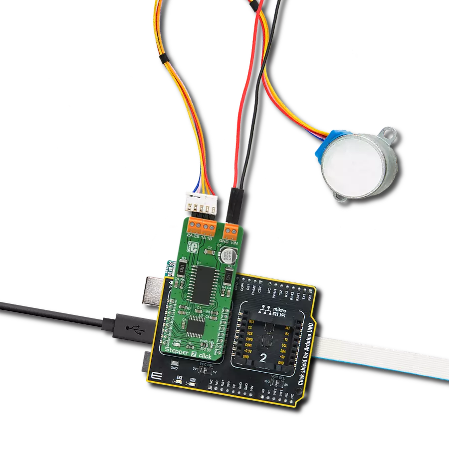
Stepper 7 Click
Dev. board
Arduino UNO Rev3
Compiler
NECTO Studio
MCU
ATmega328P
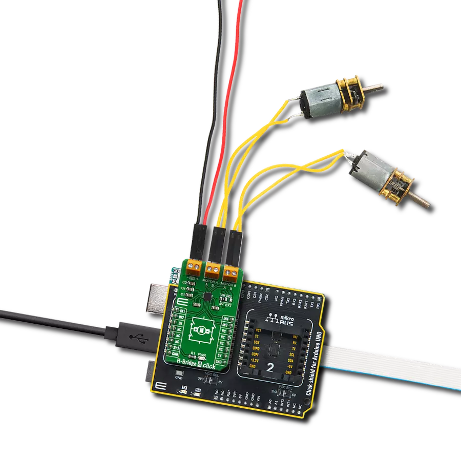
Capable of driving both windings of a bipolar stepper motor or bidirectionally control two DC motors
A
A
Hardware Overview
How does it work?
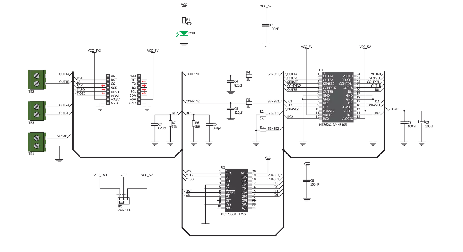
Stepper 7 Click is based on the MTS62C19A, a dual full-bridge motor driver from Microchip. This IC's internal structure is symmetrical. It features two MOSFET H-bridges used to drive two coils of a bipolar step motor in both directions. The MTS62C19A uses a wide input voltage range - from 10V to 30V. This is the voltage used to energize the motor coils. A separate voltage level is used for the logic sections of this IC, and it is obtained from the mikroBUS™ +5V rail. The MTS62C19A has two PHASE inputs, which control the direction of current flow through H-bridges and, thus, the motor coils. The output current level is controlled by an internal PWM circuit, which is configured using two logic inputs (Ix0 and Ix1), a current sense resistor, and the voltage on the VREFx input - set to +5V on the Stepper 7 Click. By setting states on the Ix0 and Ix1 pins, the output current through the motor windings can be limited to 0%, 33%, 67%, and 100% of the maximum output current, which is set to about 500mA. This setup allows controlling the
step motor in both full-step and half-step modes by toggling states on the six control pins: PHASE1, PHASE2, I01, I02, I11, and I12. The bipolar step motor coils can be connected to the onboard screw terminals. There are two terminals used to connect each of the step motor coils. The third connector connects an external voltage, ranging from 10V to 30V, depending on the used motor voltage requirements. It should be noted that without a valid external voltage connected to this terminal, the motor will not work. Also, 40V is the absolute maximum voltage allowed as per the datasheet. Thus, the overtemperature protection might be activated when driving heavier loads. The recommended maximum voltage should not exceed 30V, as stated on the silk layer of the PCB. The MTS62C19A control lines are routed to the second IC on the Stepper 7 board, the MCP23S08, a well-known 8-bit I/O expander with a serial interface. It allows the control lines of the MTS62C19A IC to be driven via the SPI and the few pins it uses -
reducing the required pin count of the Stepper 7 click. This also allows for sending compact SPI messages instead of toggling several pins at once - which can introduce problems with timing sometimes, especially when those pins belong to different MCU ports. Changing the supply voltage for the port expander allows different SPI logic levels to be used for the communication - 3.3V or 5V, depending on the host MCU. This can be accomplished by switching the position of the onboard SMD jumper, labeled as PWR SEL. This Click board™ can operate with either 3.3V or 5V logic voltage levels selected via the PWR SEL jumper. This way, both 3.3V and 5V capable MCUs can use the communication lines properly. Also, this Click board™ comes equipped with a library containing easy-to-use functions and an example code that can be used as a reference for further development.

Features overview
Development board
Arduino UNO is a versatile microcontroller board built around the ATmega328P chip. It offers extensive connectivity options for various projects, featuring 14 digital input/output pins, six of which are PWM-capable, along with six analog inputs. Its core components include a 16MHz ceramic resonator, a USB connection, a power jack, an
ICSP header, and a reset button, providing everything necessary to power and program the board. The Uno is ready to go, whether connected to a computer via USB or powered by an AC-to-DC adapter or battery. As the first USB Arduino board, it serves as the benchmark for the Arduino platform, with "Uno" symbolizing its status as the
first in a series. This name choice, meaning "one" in Italian, commemorates the launch of Arduino Software (IDE) 1.0. Initially introduced alongside version 1.0 of the Arduino Software (IDE), the Uno has since become the foundational model for subsequent Arduino releases, embodying the platform's evolution.

Microcontroller Overview
MCU Card / MCU

Architecture
AVR
MCU Memory (KB)
32
Silicon Vendor
Microchip
Pin count
28
RAM (Bytes)
2048
You complete me!
Accessories
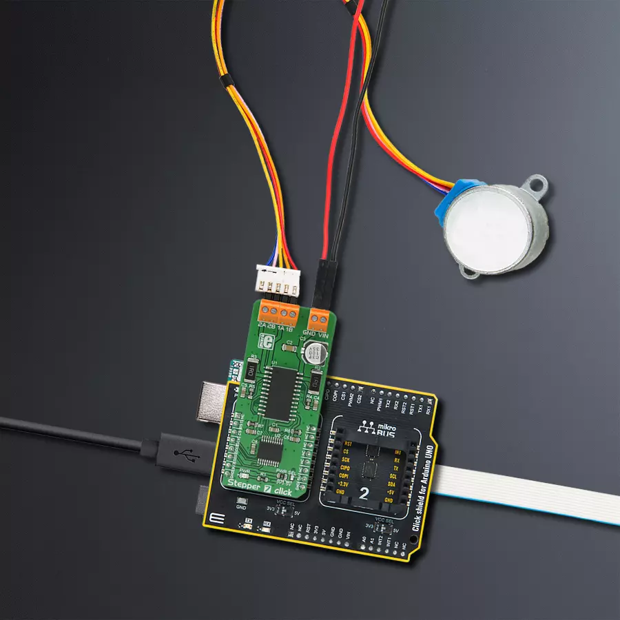
Click Shield for Arduino UNO has two proprietary mikroBUS™ sockets, allowing all the Click board™ devices to be interfaced with the Arduino UNO board without effort. The Arduino Uno, a microcontroller board based on the ATmega328P, provides an affordable and flexible way for users to try out new concepts and build prototypes with the ATmega328P microcontroller from various combinations of performance, power consumption, and features. The Arduino Uno has 14 digital input/output pins (of which six can be used as PWM outputs), six analog inputs, a 16 MHz ceramic resonator (CSTCE16M0V53-R0), a USB connection, a power jack, an ICSP header, and reset button. Most of the ATmega328P microcontroller pins are brought to the IO pins on the left and right edge of the board, which are then connected to two existing mikroBUS™ sockets. This Click Shield also has several switches that perform functions such as selecting the logic levels of analog signals on mikroBUS™ sockets and selecting logic voltage levels of the mikroBUS™ sockets themselves. Besides, the user is offered the possibility of using any Click board™ with the help of existing bidirectional level-shifting voltage translators, regardless of whether the Click board™ operates at a 3.3V or 5V logic voltage level. Once you connect the Arduino UNO board with our Click Shield for Arduino UNO, you can access hundreds of Click boards™, working with 3.3V or 5V logic voltage levels.

The 28BYJ-48 is an adaptable 5VDC stepper motor with a compact design, ideal for various applications. It features four phases, a speed variation ratio of 1/64, and a stride angle of 5.625°/64 steps, allowing precise control. The motor operates at a frequency of 100Hz and has a DC resistance of 50Ω ±7% at 25°C. It boasts an idle in-traction frequency greater than 600Hz and an idle out-traction frequency exceeding 1000Hz, ensuring reliability in different scenarios. With a self-positioning torque and in-traction torque both exceeding 34.3mN.m at 120Hz, the 28BYJ-48 offers robust performance. Its friction torque ranges from 600 to 1200 gf.cm, while the pull-in torque is 300 gf.cm. This motor makes a reliable and efficient choice for your stepper motor needs.

Used MCU Pins
mikroBUS™ mapper
Take a closer look
Click board™ Schematic
Step by step
Project assembly

Start by selecting your development board and Click board™. Begin with the Arduino UNO Rev3 as your development board.


Track your results in real time
Application Output
1. Application Output - In Debug mode, the 'Application Output' window enables real-time data monitoring, offering direct insight into execution results. Ensure proper data display by configuring the environment correctly using the provided tutorial.

2. UART Terminal - Use the UART Terminal to monitor data transmission via a USB to UART converter, allowing direct communication between the Click board™ and your development system. Configure the baud rate and other serial settings according to your project's requirements to ensure proper functionality. For step-by-step setup instructions, refer to the provided tutorial.

3. Plot Output - The Plot feature offers a powerful way to visualize real-time sensor data, enabling trend analysis, debugging, and comparison of multiple data points. To set it up correctly, follow the provided tutorial, which includes a step-by-step example of using the Plot feature to display Click board™ readings. To use the Plot feature in your code, use the function: plot(*insert_graph_name*, variable_name);. This is a general format, and it is up to the user to replace 'insert_graph_name' with the actual graph name and 'variable_name' with the parameter to be displayed.

Software Support
Library Description
This library contains API for Stepper 7 Click driver.
Key functions:
stepper7_set_direction- This function sets the motor direction to clockwise or counter-clockwise in ctx->directionstepper7_set_step_mode- This function sets the step mode resolution settings in ctx->step_modestepper7_drive_motor- This function drives the motor for the specific number of steps at the selected speed
Open Source
Code example
The complete application code and a ready-to-use project are available through the NECTO Studio Package Manager for direct installation in the NECTO Studio. The application code can also be found on the MIKROE GitHub account.
/*!
 * @file main.c
 * @brief Stepper 7 Click example
 *
 * # Description
 * This example demonstrates the use of the Stepper 7 Click board by driving the
 * motor in both directions for a desired number of steps.
 *
 * The demo application is composed of two sections :
 *
 * ## Application Init
 * Initializes the driver and performs the Click default configuration.
 *
 * ## Application Task
 * Drives the motor clockwise for 200 full steps and then counter-clockiwse for 200 half
 * steps and 800 1/8th steps with 2 seconds delay on driving mode change. All data is
 * being logged on the USB UART where you can track the program flow.
 *
 * @author Stefan Filipovic
 *
 */

#include "board.h"
#include "log.h"
#include "stepper7.h"

static stepper7_t stepper7;
static log_t logger;

void application_init ( void )
{
    log_cfg_t log_cfg;  /**< Logger config object. */
    stepper7_cfg_t stepper7_cfg;  /**< Click config object. */

    /**
     * Logger initialization.
     * Default baud rate: 115200
     * Default log level: LOG_LEVEL_DEBUG
     * @note If USB_UART_RX and USB_UART_TX
     * are defined as HAL_PIN_NC, you will
     * need to define them manually for log to work.
     * See @b LOG_MAP_USB_UART macro definition for detailed explanation.
     */
    LOG_MAP_USB_UART( log_cfg );
    log_init( &logger, &log_cfg );
    log_info( &logger, " Application Init " );

    // Click initialization.
    stepper7_cfg_setup( &stepper7_cfg );
    STEPPER7_MAP_MIKROBUS( stepper7_cfg, MIKROBUS_1 );
    if ( SPI_MASTER_ERROR == stepper7_init( &stepper7, &stepper7_cfg ) )
    {
        log_error( &logger, " Communication init." );
        for ( ; ; );
    }

    if ( STEPPER7_ERROR == stepper7_default_cfg ( &stepper7 ) )
    {
        log_error( &logger, " Default configuration." );
        for ( ; ; );
    }

    log_info( &logger, " Application Task " );
}

void application_task ( void )
{
    log_printf ( &logger, " Move 200 full steps clockwise, speed: slow\r\n\n" );
    stepper7_set_direction ( &stepper7, STEPPER7_DIR_CW );
    stepper7_set_step_mode ( &stepper7, STEPPER7_MODE_FULL_STEP );
    stepper7_drive_motor ( &stepper7, 200, STEPPER7_SPEED_SLOW );
    Delay_ms ( 1000 );
    Delay_ms ( 1000 );

    log_printf ( &logger, " Move 200 half steps counter-clockwise, speed: medium\r\n\n" );
    stepper7_set_direction ( &stepper7, STEPPER7_DIR_CCW );
    stepper7_set_step_mode ( &stepper7, STEPPER7_MODE_HALF_STEP );
    stepper7_drive_motor ( &stepper7, 200, STEPPER7_SPEED_MEDIUM );
    Delay_ms ( 1000 );
    Delay_ms ( 1000 );

    log_printf ( &logger, " Move 800 1/8th steps counter-clockwise, speed: fast\r\n\n" );
    stepper7_set_direction ( &stepper7, STEPPER7_DIR_CCW );
    stepper7_set_step_mode ( &stepper7, STEPPER7_MODE_1_OVER_8_STEP );
    stepper7_drive_motor ( &stepper7, 800, STEPPER7_SPEED_FAST );
    Delay_ms ( 1000 );
    Delay_ms ( 1000 );
}

int main ( void )
{
    /* Do not remove this line or clock might not be set correctly. */
    #ifdef PREINIT_SUPPORTED
    preinit();
    #endif

    application_init( );

    for ( ; ; )
    {
        application_task( );
    }

    return 0;
}

// ------------------------------------------------------------------------ END
Additional Support
Resources
Category:Stepper