Reduce noise pollution with actionable data and insights using MCP4921 and ATmega328P
Respond promptly to noise-related issues

Published Feb 14, 2024
Click board™
Noise Click
Dev. board
Arduino UNO Rev3
Compiler
NECTO Studio
MCU
ATmega328P
Our noise detection solution is engineered to identify and mitigate disruptive noise, fostering quieter and more peaceful environments
A
A
Hardware Overview
How does it work?
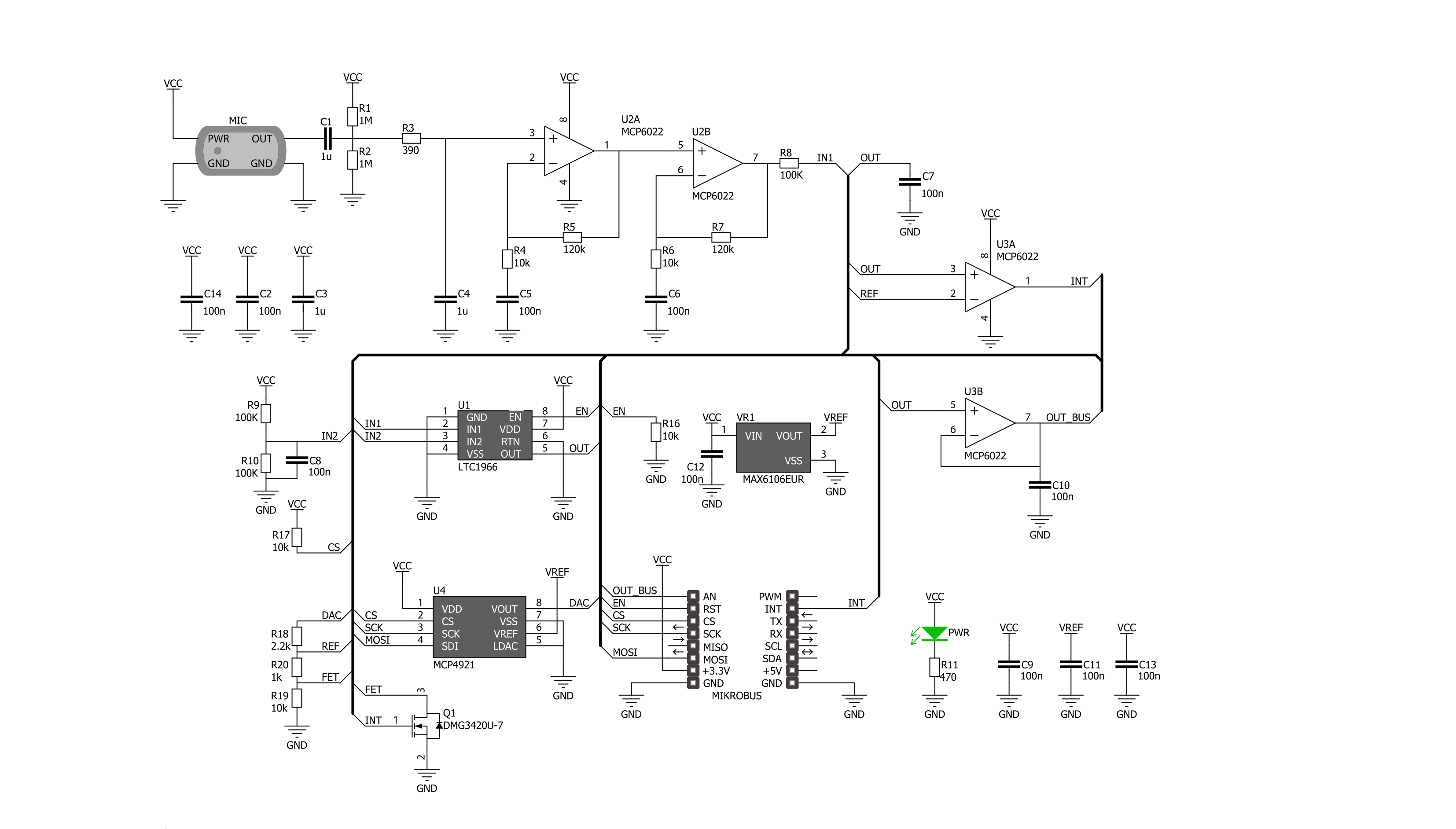
Noise Click is based on the MCP4921, a 12-bit DAC with an SPI interface from Microchip. This single-channel DAC has a rail-to-rail output, a fast-setting time, and 450KHz of multiplier mode. The MCP4921 on the Noise Click sets the threshold in 12-bit resolution steps from 0 up to 4096. The noise from the environment this Click board™ receives through the MM034202-11, an analog MEMS microphone from DB Unlimited. It has omnidirectional directivity, a sensitivity of around -42dB, a signal-to-noise ratio of 59dB, and works in a frequency range from 100 up to 10000Hz. This Click board™ also includes two MCP6022s, a rail-to-rail input/output 10MHz Op Amps from Microchip. The operational amplifiers feature wide bandwidth up to 10MHz, low noise, low input offset voltage, and low distortion. The first MCP6022
processes the microphone signal. Then, the amplified voltages pass through the LTC1966, a precision micropower ∆∑ RMS-to-DC converter from Analog Devices. This converter has constant bandwidth independent of the input voltage, flexible rail-to-rail inputs, and outputs and is more accurate than conventional log antilog similar RMS-to-DC converters. After processing with the LTC1966, the signal then goes into the second operational amplifier, which functions as a voltage comparator, from which the interrupt signal originates. To avoid triggering the interrupt hundreds of times per second as ambient noise oscillates near the threshold, a hysteresis circuit is also employed. For that purpose, the Noise Click comes with the MAX6106, a low-cost, micropower, low-dropout, high-output-current voltage
reference of 2.048V from Analog Devices. The Noise Click uses an SPI serial interface to communicate with the host MCU over the mikroBUS™ socket. The LTC1966 RMS-to-DC converter can be turned off with the HIGH logic state on the EN pin of the mikroBUS™ socket. No matter the logic state on the enable pin, the voltage levels can still be monitored over the AN pin. When the ambient noise reaches the set threshold, the interrupt INT pin is pulled HIGH. This Click board™ can be operated only with a 3.3V logic voltage level. The board must perform appropriate logic voltage level conversion before using MCUs with different logic levels. Also, it comes equipped with a library containing functions and an example code that can be used as a reference for further development.


Features overview
Development board
Arduino UNO is a versatile microcontroller board built around the ATmega328P chip. It offers extensive connectivity options for various projects, featuring 14 digital input/output pins, six of which are PWM-capable, along with six analog inputs. Its core components include a 16MHz ceramic resonator, a USB connection, a power jack, an
ICSP header, and a reset button, providing everything necessary to power and program the board. The Uno is ready to go, whether connected to a computer via USB or powered by an AC-to-DC adapter or battery. As the first USB Arduino board, it serves as the benchmark for the Arduino platform, with "Uno" symbolizing its status as the
first in a series. This name choice, meaning "one" in Italian, commemorates the launch of Arduino Software (IDE) 1.0. Initially introduced alongside version 1.0 of the Arduino Software (IDE), the Uno has since become the foundational model for subsequent Arduino releases, embodying the platform's evolution.

Microcontroller Overview
MCU Card / MCU

Architecture
AVR
MCU Memory (KB)
32
Silicon Vendor
Microchip
Pin count
28
RAM (Bytes)
2048
You complete me!
Accessories
Click Shield for Arduino UNO has two proprietary mikroBUS™ sockets, allowing all the Click board™ devices to be interfaced with the Arduino UNO board without effort. The Arduino Uno, a microcontroller board based on the ATmega328P, provides an affordable and flexible way for users to try out new concepts and build prototypes with the ATmega328P microcontroller from various combinations of performance, power consumption, and features. The Arduino Uno has 14 digital input/output pins (of which six can be used as PWM outputs), six analog inputs, a 16 MHz ceramic resonator (CSTCE16M0V53-R0), a USB connection, a power jack, an ICSP header, and reset button. Most of the ATmega328P microcontroller pins are brought to the IO pins on the left and right edge of the board, which are then connected to two existing mikroBUS™ sockets. This Click Shield also has several switches that perform functions such as selecting the logic levels of analog signals on mikroBUS™ sockets and selecting logic voltage levels of the mikroBUS™ sockets themselves. Besides, the user is offered the possibility of using any Click board™ with the help of existing bidirectional level-shifting voltage translators, regardless of whether the Click board™ operates at a 3.3V or 5V logic voltage level. Once you connect the Arduino UNO board with our Click Shield for Arduino UNO, you can access hundreds of Click boards™, working with 3.3V or 5V logic voltage levels.

Used MCU Pins
mikroBUS™ mapper
Take a closer look
Click board™ Schematic
Step by step
Project assembly

Start by selecting your development board and Click board™. Begin with the Arduino UNO Rev3 as your development board.


Software Support
Library Description
This library contains API for Noise Click driver.
Key functions:
noise_set_cmd_reg- This function sets command registernoise_set_state- This function switches click ON or OFFnoise_read_an_pin_voltage- This function reads results of AD conversion of the AN pin and converts them to proportional voltage level
Open Source
Code example
The complete application code and a ready-to-use project are available through the NECTO Studio Package Manager for direct installation in the NECTO Studio. The application code can also be found on the MIKROE GitHub account.
/*!
 * \file
 * \brief Noise Click example
 *
 * # Description
 * This example performs an ambient noise monitoring using the Noise Click board.
 *
 * The demo application is composed of two sections :
 *
 * ## Application Init
 * Device initialization.
 *
 * ## Application Task
 * Reads the voltage from AN pin which presents the noise level and displays it
 * on the USB UART every 5ms. If the noise is above predefined threshold
 * (25 percents of max noise, i.e. about 0.4V) an alarm message is being shown.
 *
 * @note
 * We recommend using the SerialPlot tool for data visualizing.
 *
 * \author MikroE Team
 *
 */
#include "board.h"
#include "log.h"
#include "noise.h"

static noise_t noise;
static log_t logger;

void application_init ( void )
{
    log_cfg_t log_cfg;
    noise_cfg_t cfg;

    /**
     * Logger initialization.
     * Default baud rate: 115200
     * Default log level: LOG_LEVEL_DEBUG
     * @note If USB_UART_RX and USB_UART_TX
     * are defined as HAL_PIN_NC, you will
     * need to define them manually for log to work.
     * See @b LOG_MAP_USB_UART macro definition for detailed explanation.
     */
    LOG_MAP_USB_UART( log_cfg );
    log_init( &logger, &log_cfg );
    log_info( &logger, "---- Application Init ----" );

    //  Click initialization.
    noise_cfg_setup( &cfg );
    NOISE_MAP_MIKROBUS( cfg, MIKROBUS_1 );
    noise_init( &noise, &cfg );

    noise_default_cfg( &noise );
}

void application_task ( void )
{
    float voltage = 0;
    if ( NOISE_OK == noise_read_an_pin_voltage ( &noise, &voltage ) )
    {
        log_printf( &logger, "%.3f\r\n", voltage );
    }
    if ( noise_check_int_pin( &noise ) )
    {
        log_printf( &logger, " Sound overlimit detected!\r\n" );
    }
    Delay_ms ( 5 );
}

int main ( void )
{
    /* Do not remove this line or clock might not be set correctly. */
    #ifdef PREINIT_SUPPORTED
    preinit();
    #endif

    application_init( );

    for ( ; ; )
    {
        application_task( );
    }

    return 0;
}


// ------------------------------------------------------------------------ END
Additional Support
Resources
Category:Microphone