Design a convenient and portable charging solution with RT9480 and ATmega328P
Recharge on the fly
Published Feb 14, 2024
Click board™
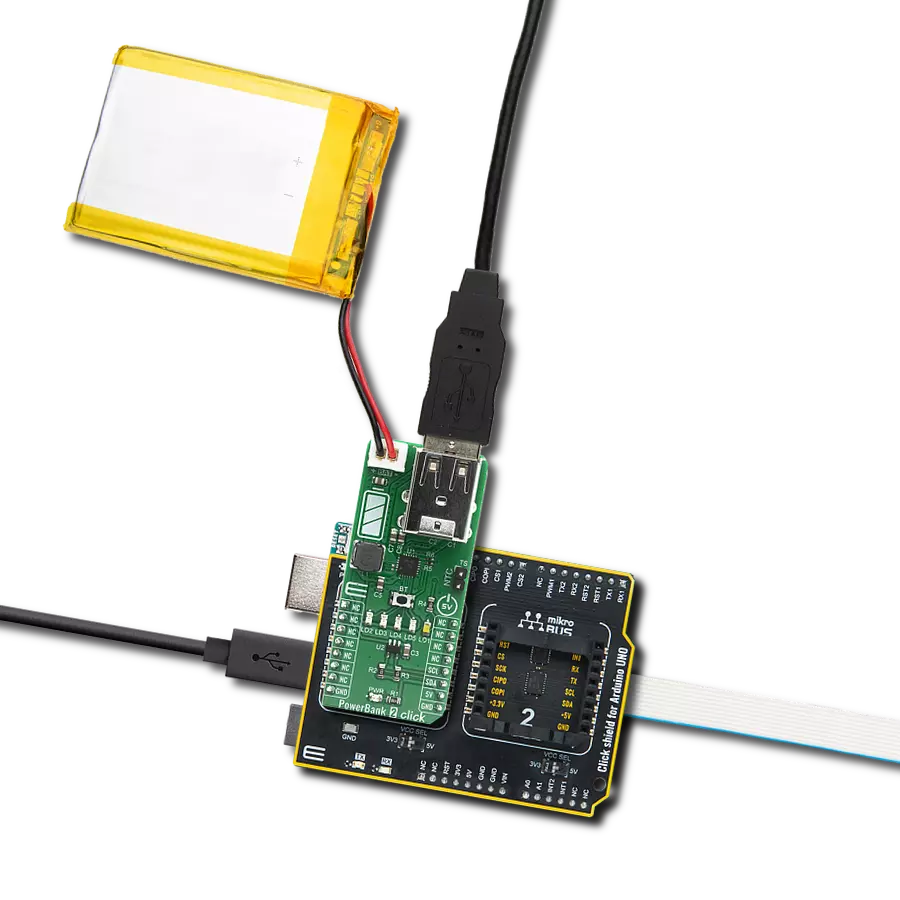
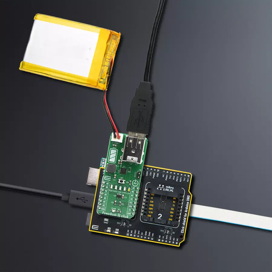
PowerBank 2 Click
Dev. board
Arduino UNO Rev3
Compiler
NECTO Studio
MCU
ATmega328P
Supercharge your solution's charging capabilities with this compact, durable, and incredibly efficient power bank solution - the ultimate addition to your design, ensuring uninterrupted power on the go
A
A
Hardware Overview
How does it work?
PowerBank 2 Click is based on the RT9480, a highly integrated IC for Li-Ion battery power bank from Richtek. It includes a linear charger 1.2A, a synchronous Boost 5.1V, two output load management, an LED indicator, and a torch function. Based on the thermal regulation function, the charging current can support up to 1.2A If the input voltage (VBUS) is higher than the threshold voltage VOVP, the internal OVP signal will go high, and the charger will stop charging until VIN is below VOVP − ΔVOVP and if the internal voltage (VMID) is higher than the threshold voltage VOVP, the internal OVP signal will go high, and the charger will stop charging until VMID is below VOVP − ΔVOVP. The converter senses the current signal when the high-side P-MOSFET turns on. As a result, The OCP is a cycle-by-cycle current limitation. If the OCP occurs, the converter holds off the next pulse until the inductor
current drops below the OCP limit. It also has over-temperature protection. When the junction temperature exceeds the thermal shutdown rising threshold, the system will be latched, and the output voltage will no longer be regulated until the junction temperature drops under the falling threshold. In the case of output short to ground, the system will be latched, and the output voltage will no longer be regulated until the power is reset. Constant current loops, voltage loops, and thermal regulation loops control the charging current. The temperature sense input TS pin can be connected to a thermistor to determine whether the battery is too hot or cold for charging. If the battery's temperature is out of range, charging is paused until it re-enters the valid range. A 4-LED indicates battery volume and the state of charging and discharging. Together with torch-light
control, the RT9480 provides an all-in-one solution for power banks and similar applications without an external microcontroller. Detailed information about LED indicators can be found in the RT9480 datasheet. The PowerBank 2 Click is also equipped with an MCP3221, a successive approximation A/D converter (ADC) with a 12-bit resolution to monitor battery voltage over an I2C bus over a mikroBUS™ socket. This Click board™ can only be operated with a 3.3V logic voltage level. The board must perform appropriate logic voltage level conversion before using MCUs with different logic levels. However, the Click board™ comes equipped with a library containing functions and an example code that can be used as a reference for further development.

Features overview
Development board
Arduino UNO is a versatile microcontroller board built around the ATmega328P chip. It offers extensive connectivity options for various projects, featuring 14 digital input/output pins, six of which are PWM-capable, along with six analog inputs. Its core components include a 16MHz ceramic resonator, a USB connection, a power jack, an
ICSP header, and a reset button, providing everything necessary to power and program the board. The Uno is ready to go, whether connected to a computer via USB or powered by an AC-to-DC adapter or battery. As the first USB Arduino board, it serves as the benchmark for the Arduino platform, with "Uno" symbolizing its status as the
first in a series. This name choice, meaning "one" in Italian, commemorates the launch of Arduino Software (IDE) 1.0. Initially introduced alongside version 1.0 of the Arduino Software (IDE), the Uno has since become the foundational model for subsequent Arduino releases, embodying the platform's evolution.

Microcontroller Overview
MCU Card / MCU

Architecture
AVR
MCU Memory (KB)
32
Silicon Vendor
Microchip
Pin count
28
RAM (Bytes)
2048
You complete me!
Accessories
Click Shield for Arduino UNO has two proprietary mikroBUS™ sockets, allowing all the Click board™ devices to be interfaced with the Arduino UNO board without effort. The Arduino Uno, a microcontroller board based on the ATmega328P, provides an affordable and flexible way for users to try out new concepts and build prototypes with the ATmega328P microcontroller from various combinations of performance, power consumption, and features. The Arduino Uno has 14 digital input/output pins (of which six can be used as PWM outputs), six analog inputs, a 16 MHz ceramic resonator (CSTCE16M0V53-R0), a USB connection, a power jack, an ICSP header, and reset button. Most of the ATmega328P microcontroller pins are brought to the IO pins on the left and right edge of the board, which are then connected to two existing mikroBUS™ sockets. This Click Shield also has several switches that perform functions such as selecting the logic levels of analog signals on mikroBUS™ sockets and selecting logic voltage levels of the mikroBUS™ sockets themselves. Besides, the user is offered the possibility of using any Click board™ with the help of existing bidirectional level-shifting voltage translators, regardless of whether the Click board™ operates at a 3.3V or 5V logic voltage level. Once you connect the Arduino UNO board with our Click Shield for Arduino UNO, you can access hundreds of Click boards™, working with 3.3V or 5V logic voltage levels.

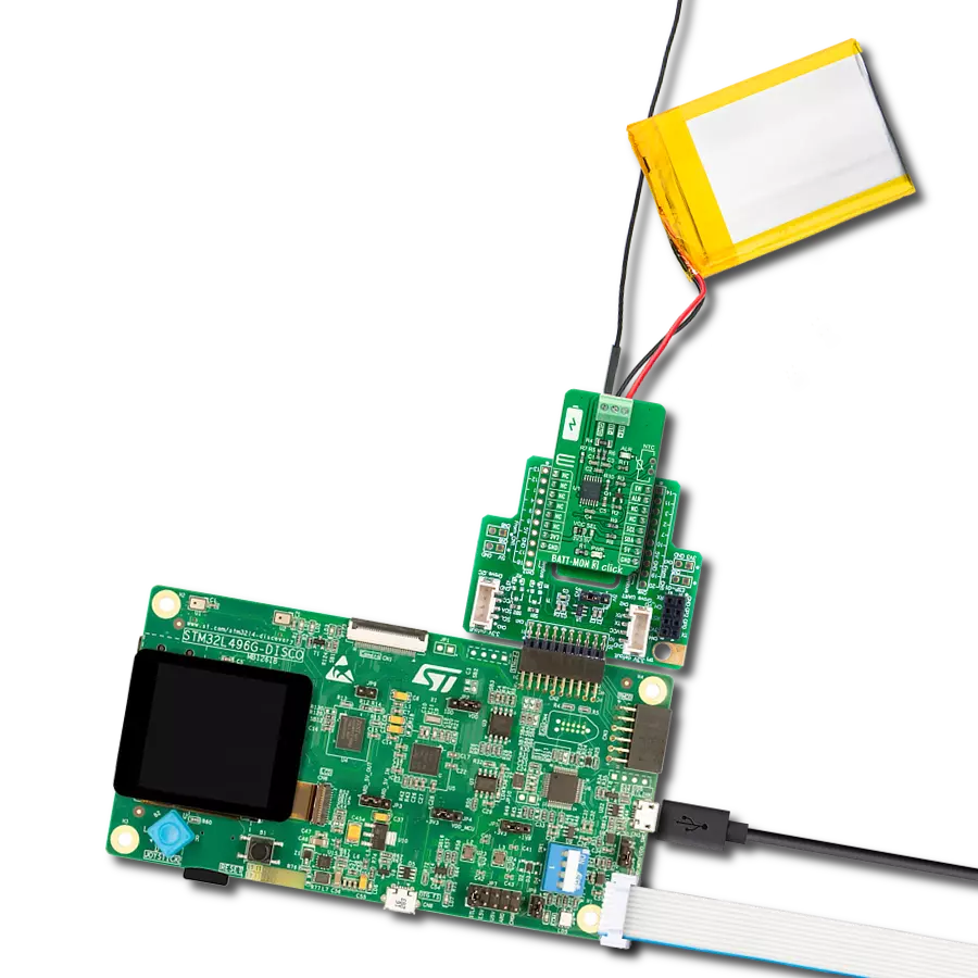
Li-Polymer Battery is the ideal solution for devices that demand a dependable and long-lasting power supply while emphasizing mobility. Its compatibility with mikromedia boards ensures easy integration without additional modifications. With a voltage output of 3.7V, the battery meets the standard requirements of many electronic devices. Additionally, boasting a capacity of 2000mAh, it can store a substantial amount of energy, providing sustained power for extended periods. This feature minimizes the need for frequent recharging or replacement. Overall, the Li-Polymer Battery is a reliable and autonomous power source, ideally suited for devices requiring a stable and enduring energy solution. You can find a more extensive choice of Li-Polymer batteries in our offer.

Used MCU Pins
mikroBUS™ mapper
Take a closer look
Click board™ Schematic

Step by step
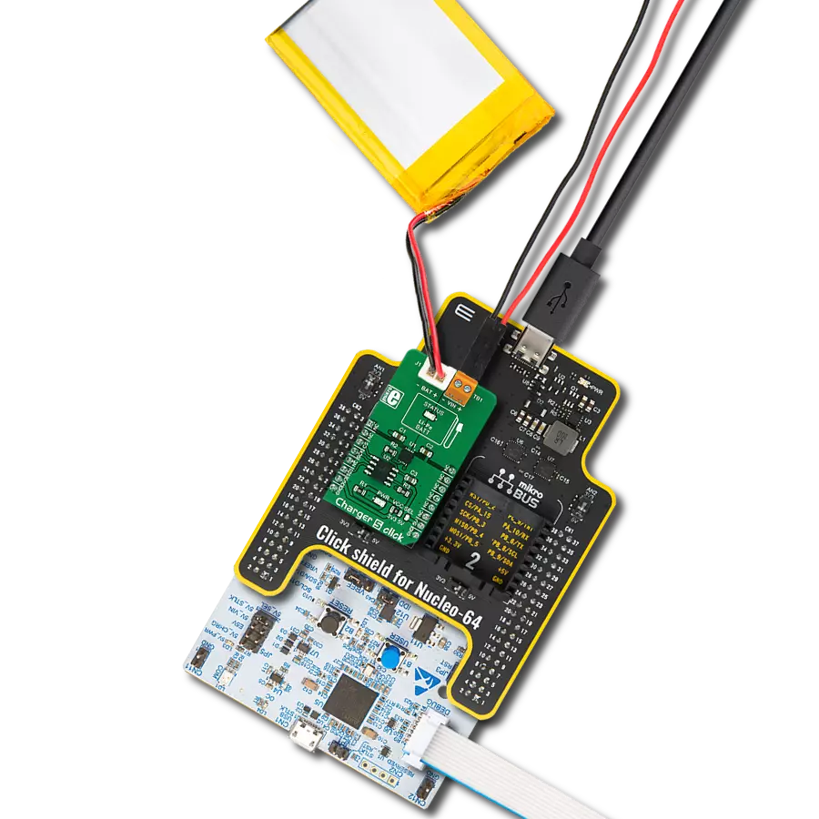
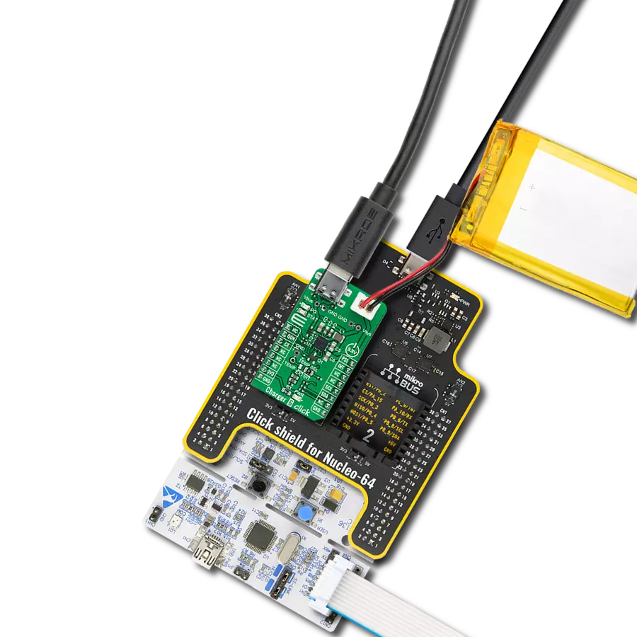
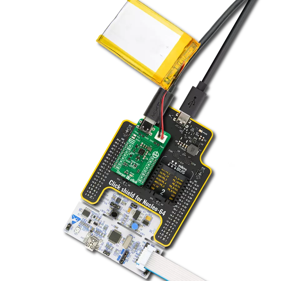
Project assembly

Start by selecting your development board and Click board™. Begin with the Arduino UNO Rev3 as your development board.


Track your results in real time
Application Output
1. Application Output - In Debug mode, the 'Application Output' window enables real-time data monitoring, offering direct insight into execution results. Ensure proper data display by configuring the environment correctly using the provided tutorial.

2. UART Terminal - Use the UART Terminal to monitor data transmission via a USB to UART converter, allowing direct communication between the Click board™ and your development system. Configure the baud rate and other serial settings according to your project's requirements to ensure proper functionality. For step-by-step setup instructions, refer to the provided tutorial.

3. Plot Output - The Plot feature offers a powerful way to visualize real-time sensor data, enabling trend analysis, debugging, and comparison of multiple data points. To set it up correctly, follow the provided tutorial, which includes a step-by-step example of using the Plot feature to display Click board™ readings. To use the Plot feature in your code, use the function: plot(*insert_graph_name*, variable_name);. This is a general format, and it is up to the user to replace 'insert_graph_name' with the actual graph name and 'variable_name' with the parameter to be displayed.

Software Support
Library Description
This library contains API for PowerBank 2 Click driver.
Key functions:
uint16_t powerbank2_read_data ( );- Function is used to read raw data from MCP3221.uint16_t powerbank2_read_voltage ( uint16_t v_ref );- Function is used to calculate voltage of the connected battery.
Open Source
Code example
The complete application code and a ready-to-use project are available through the NECTO Studio Package Manager for direct installation in the NECTO Studio. The application code can also be found on the MIKROE GitHub account.
/*!
 * \file
 * \brief Powerbank2 Click example
 *
 * # Description
 * This single chip includes a linear charger, a synchronous Boost with dual output load
 * management and a torch function support.
 *
 * The demo application is composed of two sections :
 *
 * ## Application Init
 * Initalizes I2C driver and makes an initial log.
 *
 * ## Application Task
 * This example shows the capabilities of the Power Bank 2 Click
 * by measuring voltage of the connected battery. In order to get correct calculations
 * the user should change "v_ref" value to his own power supply voltage.
 *
 * \author MikroE Team
 *
 */
// ------------------------------------------------------------------- INCLUDES

#include "board.h"
#include "log.h"
#include "powerbank2.h"

// ------------------------------------------------------------------ VARIABLES

static powerbank2_t powerbank2;
static log_t logger;

static uint16_t voltage;
static uint16_t v_ref = 5000; // milivolts

// ------------------------------------------------------ APPLICATION FUNCTIONS

void application_init ( void )
{
    log_cfg_t log_cfg;
    powerbank2_cfg_t cfg;

    /**
     * Logger initialization.
     * Default baud rate: 115200
     * Default log level: LOG_LEVEL_DEBUG
     * @note If USB_UART_RX and USB_UART_TX
     * are defined as HAL_PIN_NC, you will
     * need to define them manually for log to work.
     * See @b LOG_MAP_USB_UART macro definition for detailed explanation.
     */
    LOG_MAP_USB_UART( log_cfg );
    log_init( &logger, &log_cfg );
    log_info( &logger, "---- Application Init ----" );

    //  Click initialization.

    powerbank2_cfg_setup( &cfg );
    POWERBANK2_MAP_MIKROBUS( cfg, MIKROBUS_1 );
    powerbank2_init( &powerbank2, &cfg );
}

void application_task ( void )
{
    voltage = powerbank2_read_voltage( &powerbank2, v_ref );

    log_printf( &logger, "Battery voltage: %u mV\r\n", voltage );

    Delay_ms ( 1000 );
    Delay_ms ( 1000 );
}

int main ( void )
{
    /* Do not remove this line or clock might not be set correctly. */
    #ifdef PREINIT_SUPPORTED
    preinit();
    #endif

    application_init( );

    for ( ; ; )
    {
        application_task( );
    }

    return 0;
}

// ------------------------------------------------------------------------ END
Additional Support
Resources
Category:Battery charger