Unlock the full potential of any battery with SPV1050 and STM32F031K6
Embrace the future of battery charging

Published Oct 01, 2024
Click board™
Peltier Click
Dev. board
Nucleo 32 with STM32F031K6 MCU
Compiler
NECTO Studio
MCU
STM32F031K6
Charge any battery type, including lithium-based, solid-state thin film and super-capacitor
A
A
Hardware Overview
How does it work?
Peltier Click is based on the SPV1050, an ultralow power energy harvester and battery charger from STMicroelectronics that can charge lithium-based batteries. A thermoelectric harvester produces green energy for energy harvesting with many advantages: maintenance-free because of the use of a highly reliable and compact solid-state device; silent and quiet; highly efficient in environmental terms because the heat is harvested from waste heat sources and converted into electricity. Because of this feature, the Peltier click can be used for various applications such as WSN, HVAC, building and home automation, industrial control, remote metering, lighting, security, surveillance, and wearable and biomedical sensors. The SPV1050 is an ultralow power and high-efficiency energy harvester and battery charger, which implements the MPPT function and integrates the switching elements of a buck-boost converter. The SPV1050 device allows the charge of a lithium
battery by tightly monitoring the end-of-charge and the minimum battery voltage to avoid over-discharge and preserve the battery life. The power manager is suitable for TEG harvesting sources, as it covers the input voltage range from 75 mV up to 18 V and guarantees high efficiency in both buck-boost and boost configurations. Furthermore, the SPV1050 device shows very high flexibility thanks to the trimming capability of the end-of-charge and undervoltage protection voltages. In such a way, any source and battery are matched. The MPPT is programmable by a resistor input divider and allows maximizing the source power under any temperature and irradiance condition. Some of the key features of the SPV1050 are its transformerless thermoelectric generators and PV modules energy harvester, high efficiency for any harvesting source, and up to 70 mA maximum battery charging current. It is a fully integrated buck-boost DC-DC converter with a
programmable MPPT by external resistors, 2.6 V to 5.3 V trimmable battery charge voltage level (± 1% accuracy), 2.2 V to 3.6 V trimmable battery discharge voltage level (± 1% accuracy) with two fully independent LDOs (1.8 V and 3.3 V output). The SPV1050 can turn LDO control pins on/off, and it has a battery disconnect function for battery protection while the battery is connected and ongoing charge logic open drain indication pins. The SPV1050 is an ultralow power energy harvester with an embedded MPPT algorithm, a battery charger, and a power manager designed for applications up to 400 mW. This Click board™ can only be operated with a 3.3V logic voltage level. The board must perform appropriate logic voltage level conversion before using MCUs with different logic levels. However, the Click board™ comes equipped with a library containing functions and an example code that can be used as a reference for further development.

Features overview
Development board
Nucleo 32 with STM32F031K6 MCU board provides an affordable and flexible platform for experimenting with STM32 microcontrollers in 32-pin packages. Featuring Arduino™ Nano connectivity, it allows easy expansion with specialized shields, while being mbed-enabled for seamless integration with online resources. The
board includes an on-board ST-LINK/V2-1 debugger/programmer, supporting USB reenumeration with three interfaces: Virtual Com port, mass storage, and debug port. It offers a flexible power supply through either USB VBUS or an external source. Additionally, it includes three LEDs (LD1 for USB communication, LD2 for power,
and LD3 as a user LED) and a reset push button. The STM32 Nucleo-32 board is supported by various Integrated Development Environments (IDEs) such as IAR™, Keil®, and GCC-based IDEs like AC6 SW4STM32, making it a versatile tool for developers.

Microcontroller Overview
MCU Card / MCU

Architecture
ARM Cortex-M0
MCU Memory (KB)
32
Silicon Vendor
STMicroelectronics
Pin count
32
RAM (Bytes)
4096
You complete me!
Accessories
Click Shield for Nucleo-32 is the perfect way to expand your development board's functionalities with STM32 Nucleo-32 pinout. The Click Shield for Nucleo-32 provides two mikroBUS™ sockets to add any functionality from our ever-growing range of Click boards™. We are fully stocked with everything, from sensors and WiFi transceivers to motor control and audio amplifiers. The Click Shield for Nucleo-32 is compatible with the STM32 Nucleo-32 board, providing an affordable and flexible way for users to try out new ideas and quickly create prototypes with any STM32 microcontrollers, choosing from the various combinations of performance, power consumption, and features. The STM32 Nucleo-32 boards do not require any separate probe as they integrate the ST-LINK/V2-1 debugger/programmer and come with the STM32 comprehensive software HAL library and various packaged software examples. This development platform provides users with an effortless and common way to combine the STM32 Nucleo-32 footprint compatible board with their favorite Click boards™ in their upcoming projects.

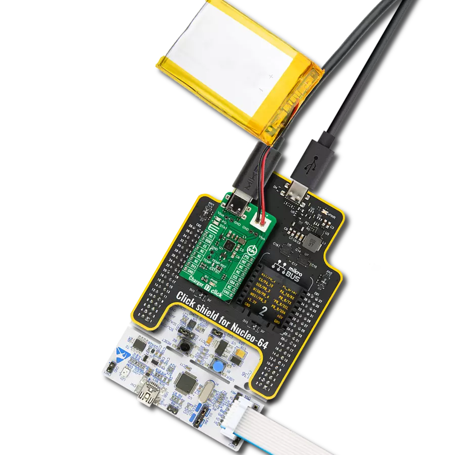
Li-Polymer Battery is the ideal solution for devices that demand a dependable and long-lasting power supply while emphasizing mobility. Its compatibility with mikromedia boards ensures easy integration without additional modifications. With a voltage output of 3.7V, the battery meets the standard requirements of many electronic devices. Additionally, boasting a capacity of 2000mAh, it can store a substantial amount of energy, providing sustained power for extended periods. This feature minimizes the need for frequent recharging or replacement. Overall, the Li-Polymer Battery is a reliable and autonomous power source, ideally suited for devices requiring a stable and enduring energy solution. You can find a more extensive choice of Li-Polymer batteries in our offer.

Used MCU Pins
mikroBUS™ mapper
Take a closer look
Click board™ Schematic

Step by step
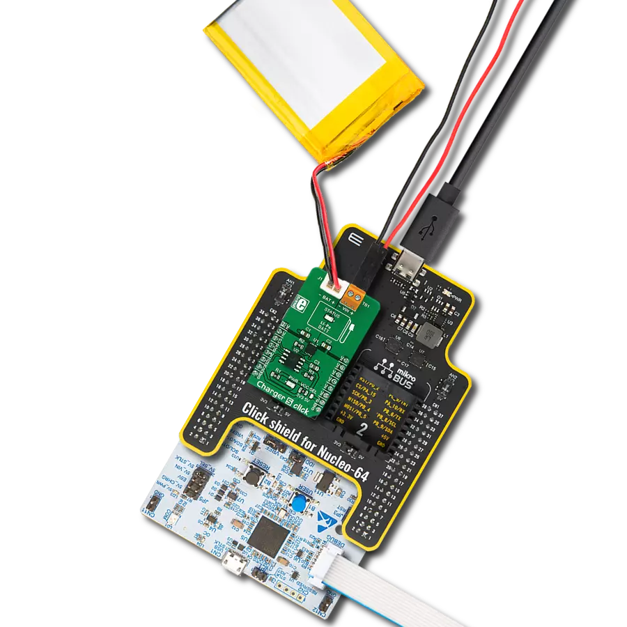
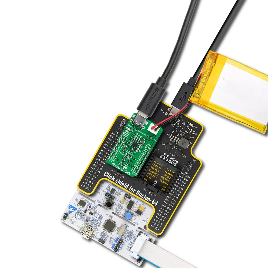
Project assembly

Start by selecting your development board and Click board™. Begin with the Nucleo 32 with STM32F031K6 MCU as your development board.


Track your results in real time
Application Output
1. Application Output - In Debug mode, the 'Application Output' window enables real-time data monitoring, offering direct insight into execution results. Ensure proper data display by configuring the environment correctly using the provided tutorial.

2. UART Terminal - Use the UART Terminal to monitor data transmission via a USB to UART converter, allowing direct communication between the Click board™ and your development system. Configure the baud rate and other serial settings according to your project's requirements to ensure proper functionality. For step-by-step setup instructions, refer to the provided tutorial.

3. Plot Output - The Plot feature offers a powerful way to visualize real-time sensor data, enabling trend analysis, debugging, and comparison of multiple data points. To set it up correctly, follow the provided tutorial, which includes a step-by-step example of using the Plot feature to display Click board™ readings. To use the Plot feature in your code, use the function: plot(*insert_graph_name*, variable_name);. This is a general format, and it is up to the user to replace 'insert_graph_name' with the actual graph name and 'variable_name' with the parameter to be displayed.

Software Support
Library Description
This library contains API for Peltier Click driver.
Key functions:
peltier_enable_ldo2- Enables LDO2 functionpeltier_disable_ldo2- Disables LDO2 functionpeltier_battery_charge- Check ongoing battery charge flag pin function
Open Source
Code example
The complete application code and a ready-to-use project are available through the NECTO Studio Package Manager for direct installation in the NECTO Studio. The application code can also be found on the MIKROE GitHub account.
/*!
 * \file
 * \brief Peltier Click example
 *
 * # Description
 * This application is ultralow power energy harvester and battery charger.
 *
 * The demo application is composed of two sections :
 *
 * ## Application Init
 * Initializes GPIO driver, disables both 1.8V and 3.3V outputs and starts write log.
 *
 * ## Application Task
 * This example demonstrates the use of Peltier Click board by first enableing 1.8V output, second
   by enableing 3.3V output, then enabling both outputs and finally disabling both outputs in 5 seconds intervals.
 *
 * \author MikroE Team
 *
 */
// ------------------------------------------------------------------- INCLUDES

#include "board.h"
#include "log.h"
#include "peltier.h"

// ------------------------------------------------------------------ VARIABLES

static peltier_t peltier;
static log_t logger;

// ------------------------------------------------------ APPLICATION FUNCTIONS

void application_init ( void )
{
    log_cfg_t log_cfg;
    peltier_cfg_t cfg;

    /**
     * Logger initialization.
     * Default baud rate: 115200
     * Default log level: LOG_LEVEL_DEBUG
     * @note If USB_UART_RX and USB_UART_TX
     * are defined as HAL_PIN_NC, you will
     * need to define them manually for log to work.
     * See @b LOG_MAP_USB_UART macro definition for detailed explanation.
     */
    LOG_MAP_USB_UART( log_cfg );
    log_init( &logger, &log_cfg );
    log_info( &logger, "---- Application Init ----" );

    //  Click initialization.

    peltier_cfg_setup( &cfg );
    PELTIER_MAP_MIKROBUS( cfg, MIKROBUS_1 );
    peltier_init( &peltier, &cfg );
}

void application_task ( void )
{
    log_printf( &logger, "   1.8V output    \r\n" );
    log_printf( &logger, "------------------\r\n" );
    peltier_enable_ldo1( &peltier );
    peltier_disable_ldo2( &peltier );
    Delay_ms ( 1000 );
    Delay_ms ( 1000 );
    Delay_ms ( 1000 );
    Delay_ms ( 1000 );
    Delay_ms ( 1000 );

    log_printf( &logger, "   3.3V output    \r\n" );
    log_printf( &logger, "------------------\r\n" );
    peltier_disable_ldo1( &peltier );
    peltier_enable_ldo2( &peltier );
    Delay_ms ( 1000 );
    Delay_ms ( 1000 );
    Delay_ms ( 1000 );
    Delay_ms ( 1000 );
    Delay_ms ( 1000 );

    log_printf( &logger, "   Both outputs   \r\n" );
    log_printf( &logger, "------------------\r\n" );
    peltier_enable_ldo1( &peltier );
    peltier_enable_ldo2( &peltier );
    Delay_ms ( 1000 );
    Delay_ms ( 1000 );
    Delay_ms ( 1000 );
    Delay_ms ( 1000 );
    Delay_ms ( 1000 );

    log_printf( &logger, " Disable  outputs \r\n" );
    log_printf( &logger, "------------------\r\n" );
    peltier_disable_ldo1( &peltier );
    peltier_disable_ldo2( &peltier );
    Delay_ms ( 1000 );
    Delay_ms ( 1000 );
    Delay_ms ( 1000 );
    Delay_ms ( 1000 );
    Delay_ms ( 1000 );
}

int main ( void )
{
    /* Do not remove this line or clock might not be set correctly. */
    #ifdef PREINIT_SUPPORTED
    preinit();
    #endif

    application_init( );

    for ( ; ; )
    {
        application_task( );
    }

    return 0;
}


// ------------------------------------------------------------------------ END
Additional Support
Resources
Category:Battery charger