Captivate audiences and enhance your storytelling abilities with ISD3900 and ATmega328P
Your personalized digital voice recorder

Published Feb 14, 2024
Click board™
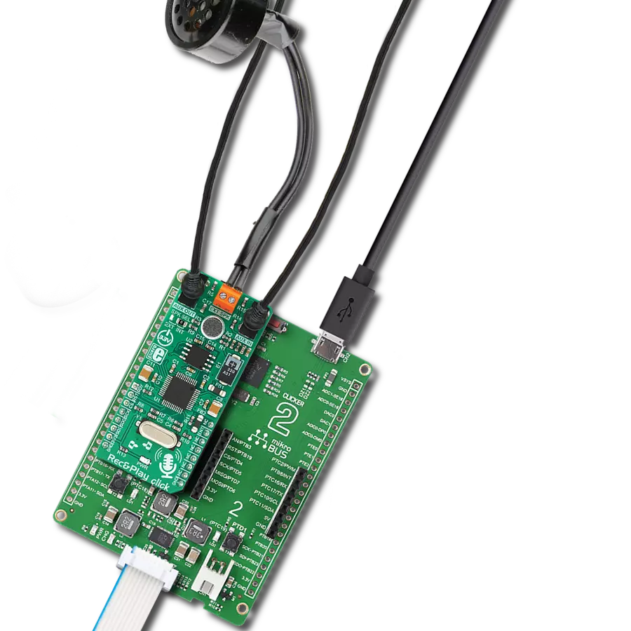
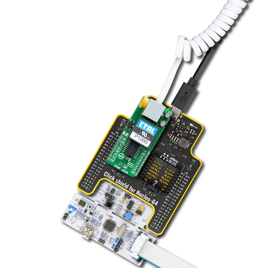
Rec&Play Click
Dev. board
Arduino UNO Rev3
Compiler
NECTO Studio
MCU
ATmega328P
Discover how our multi-message record and playback device can bring your memories to life through customizable voice recordings
A
A
Hardware Overview
How does it work?
Rec&Play Click is based on the ISD3900, a multi-message record and playback device with ChipCorder® technology, from Nuvoton. Thanks to the many useful features it offers, this IC gained its popularity very quickly. Besides several compression and de-compression CODEC, it features a fully programmable signal path with the support for several different signal types, allowing a very simple design for any kind of message-based application. Sound notification from a POS terminal, a home appliance that uses voice to notify about some event, even a Dictaphone-like device, it can all be implemented very quickly with this Click board™. Instead of using memory locations, ISD3900 allows using message indices: once stored, a message can be invoked using its index. Building of macro scripts (Voice Macros) is also possible. To allow the out-of-box functionality, the Click board™ is equipped with a small omnidirectional electret microphone, along with a miniature 8Ω speaker. The microphone is can capture a sound or voice recording. The recording can be reinforced by applying the Automatic Gain Control (AGC), which dynamically changes the input gain, helping to obtain the most appropriate signal level. The AGC function, along with many other functions, can be configured over the SPI interface. The miniature neodymium speaker (internal speaker) measures only 15 x 11mm, and it is designed to output up to 0.7W of continuous
power. It is driven by the ISD3900 IC, which integrates a small 0.5W class D amplifier. The internal speaker has an adhesive on its rims, allowing it to be easily mounted inside a small resonant box, which can reinforce its output. However, this speaker is good only when used indoors. 2-pole terminal labeled as EXT SPK allows an external passive speaker box to be connected. When the SPK SEL is moved to the EXT position, the output of the internal class D amplifier becomes routed to this connector, instead of the internal speaker. A differential BTL (Bridge-Tied Load) output is also available over the EXT SPK connector, allowing an external amplifier with differential inputs to be used. AUX IN and AUX OUT are 3.5mm jack connectors, used to connect line-level input and output signals. The AUX OUT connector offers a single-sided line-level output, compatible with most of the commercial amplifiers, active desktop speakers, sound monitors, etc. The AUX IN is a single-sided line-level input, allowing to capture sound from a home PC, TV set, MP3 player, and any other device equipped with the line-out connector. The audio sample rate is derived from an external crystal oscillator, rated at 4.096MHz. This crystal oscillator allows the master sample rate up to 32kHz. Lower sample rates can also be used, resulting in reduced sound quality. Besides the sample rate, the sound quality is also affected by the used
compression algorithm. ISD3900 supports many different CODECs. For more information, please refer to the ISD3900 IC datasheet. Besides the ISD3900 this Click board™ contains another IC: it is a non-volatile memory module labeled as W25Q64, a 64 Mbit serial Flash memory from Winbond. This memory module has a 64 Mbit density arranged in 8-bit words, allowing up to 32 minutes of audio to be stored. The ISD3900 has a set of registers that control every aspect of the device: the entire sound path can be configured by writing to the proper config registers over the SPI interface. The ISD3900 also handles Flash-related commands, such as formatting, erasing, reading, writing, and more. Although simplified, programming the ISD3900 can seem complex, but when used within the MIKROE environment, it is very easy to operate the Click board™. It is supported by the mikroSDK compatible library, which contains functions for accelerated software development. Several pre-configured sound path settings are available, saving valuable time. This Click board™ can be operated only with a 3.3V logic voltage level. The board must perform appropriate logic voltage level conversion before using MCUs with different logic levels. Also, it comes equipped with a library containing functions and an example code that can be used as a reference for further development.

Features overview
Development board
Arduino UNO is a versatile microcontroller board built around the ATmega328P chip. It offers extensive connectivity options for various projects, featuring 14 digital input/output pins, six of which are PWM-capable, along with six analog inputs. Its core components include a 16MHz ceramic resonator, a USB connection, a power jack, an
ICSP header, and a reset button, providing everything necessary to power and program the board. The Uno is ready to go, whether connected to a computer via USB or powered by an AC-to-DC adapter or battery. As the first USB Arduino board, it serves as the benchmark for the Arduino platform, with "Uno" symbolizing its status as the
first in a series. This name choice, meaning "one" in Italian, commemorates the launch of Arduino Software (IDE) 1.0. Initially introduced alongside version 1.0 of the Arduino Software (IDE), the Uno has since become the foundational model for subsequent Arduino releases, embodying the platform's evolution.

Microcontroller Overview
MCU Card / MCU

Architecture
AVR
MCU Memory (KB)
32
Silicon Vendor
Microchip
Pin count
28
RAM (Bytes)
2048
You complete me!
Accessories
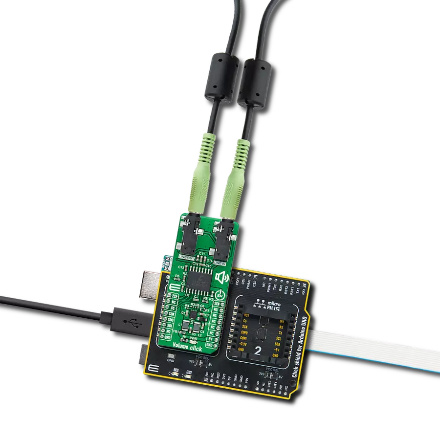
Click Shield for Arduino UNO has two proprietary mikroBUS™ sockets, allowing all the Click board™ devices to be interfaced with the Arduino UNO board without effort. The Arduino Uno, a microcontroller board based on the ATmega328P, provides an affordable and flexible way for users to try out new concepts and build prototypes with the ATmega328P microcontroller from various combinations of performance, power consumption, and features. The Arduino Uno has 14 digital input/output pins (of which six can be used as PWM outputs), six analog inputs, a 16 MHz ceramic resonator (CSTCE16M0V53-R0), a USB connection, a power jack, an ICSP header, and reset button. Most of the ATmega328P microcontroller pins are brought to the IO pins on the left and right edge of the board, which are then connected to two existing mikroBUS™ sockets. This Click Shield also has several switches that perform functions such as selecting the logic levels of analog signals on mikroBUS™ sockets and selecting logic voltage levels of the mikroBUS™ sockets themselves. Besides, the user is offered the possibility of using any Click board™ with the help of existing bidirectional level-shifting voltage translators, regardless of whether the Click board™ operates at a 3.3V or 5V logic voltage level. Once you connect the Arduino UNO board with our Click Shield for Arduino UNO, you can access hundreds of Click boards™, working with 3.3V or 5V logic voltage levels.

Used MCU Pins
mikroBUS™ mapper
Take a closer look
Click board™ Schematic

Step by step
Project assembly

Start by selecting your development board and Click board™. Begin with the Arduino UNO Rev3 as your development board.


Software Support
Library Description
This library contains API for Rec&Play Click driver.
Key functions:
recplay_read_status- Function queries the ISD3900 device statusrecplay_erase_msg- Function erases the message starting at the specified addressrecplay_record_msg- Function initiates a managed record at first available location in memory
Open Source
Code example
The complete application code and a ready-to-use project are available through the NECTO Studio Package Manager for direct installation in the NECTO Studio. The application code can also be found on the MIKROE GitHub account.
/*!
 * \file
 * \brief RecNPlay Click example
 *
 * # Description
 * This application demonstrates the processof recording a message and playing it back.
 *
 * The demo application is composed of two sections :
 *
 * ## Application Init
 * Initializes SPI interface in proper mode and performs all the necessary commands to
 * put the device in proper working mode (chip reset, chip power up, chip erasing, clock configuration).
 *
 * ## Application Task
 * Performs the chip configuration for recording message via microphone, then records a message
 * for 8 seconds to specified memory location. After that, it reads the recorded message address with message length and then plays the
 * recorded message. When playback is done it erases the recorded message from memory. Afterwards, it repeats all the operations every 10 seconds.
 *
 * *note:*
 * The ISD3900 must be properly configured to work in record mode every time when user wants to record a message.
 * When user wants to play a recorded message, then ISD3900 must be properly configured, but now to work in play mode.
 *
 * \author MikroE Team
 *
 */
// ------------------------------------------------------------------- INCLUDES

#include "board.h"
#include "log.h"
#include "recnplay.h"

// ------------------------------------------------------------------ VARIABLES

static recnplay_t recnplay;
static log_t logger;
static uint32_t msg_addr;
static uint16_t msg_len;
static uint8_t temp_var;
static uint8_t volume;
static RECNPLAY_RETVAL status_byte;
static uint8_t interr_byte;

static const uint8_t config_play_pwm_spk[ 32 ] = { 0x64, 0x00, 0x44, 0x00, 0x40, 0x00, 0x00, 0x00, 0x00, 0x00, 0x00, 0x00, 0x00, 0x00, 0x26, 0x00, 0x57, 0x01, 0x57, 0x00, 0x00, 0xFF, 0x30, 0x02, 0x00, 0x00, 0x00, 0xFF, 0x00, 0xFF, 0x00, 0x00 };
static const uint8_t config_play_aux_out[ 32 ] = { 0x64, 0x00, 0x48, 0x00, 0x40, 0x80, 0xC1, 0x00, 0x00, 0x00, 0x00, 0x00, 0x00, 0x00, 0x26, 0x00, 0x57, 0x01, 0x57, 0x00, 0x00, 0xFF, 0x30, 0x02, 0xAB, 0x00, 0x00, 0xFF, 0x00, 0xFF, 0x00, 0x00 };
static const uint8_t config_rec_mic[ 32 ]      = { 0xA4, 0x80, 0x02, 0xFF, 0x0D, 0x40, 0x50, 0x48, 0x00, 0x00, 0x00, 0x00, 0x00, 0x00, 0x28, 0x00, 0x3E, 0x00, 0xD6, 0x00, 0xFF, 0xFF, 0x11, 0x82, 0x00, 0x00, 0x00, 0xFF, 0x00, 0xFF, 0x00, 0x00 };


// ------------------------------------------------------- ADDITIONAL FUNCTIONS

void wait_cmd_fin ( void )
{
    status_byte = recplay_read_status( &recnplay, &interr_byte );
    while ( ( interr_byte != RECPLAY_INT_CMD_FIN_MASK ) ||
                ( status_byte != ( RECPLAY_STAT_DBUF_RDY_MASK | RECPLAY_STAT_INT_GEN_MASK ) ) )
    {
        status_byte = recplay_read_status( &recnplay, &interr_byte );
    }
    status_byte = recplay_read_interr( &recnplay, &interr_byte );
}

void wait_ready ( void )
{
    status_byte = recplay_read_status( &recnplay, &interr_byte );
    while ( status_byte != RECPLAY_STAT_DBUF_RDY_MASK )
    {
        status_byte = recplay_read_status( &recnplay, &interr_byte );
    }
    status_byte = recplay_read_interr( &recnplay, &interr_byte );
}

void wait_power_up ( void )
{
    status_byte = recplay_read_status( &recnplay, &interr_byte );
    while ( status_byte == RECPLAY_STAT_PWR_DOWN_MASK )
    {
        status_byte = recplay_read_status( &recnplay, &interr_byte );
    }
    status_byte = recplay_read_interr( &recnplay, &interr_byte );
}

void time_record ( uint32_t seconds_time )
{
    uint8_t cnt;
    for ( cnt = 0; cnt < seconds_time; cnt++ )
    {
        Delay_ms ( 1000 );
        log_printf( &logger, "." );
    }
}

void set_volume ( uint8_t volume_sel )
{
    uint16_t volume_res;

    if ( volume_sel > 100 )
    {
        volume = 0;
        log_printf( &logger, "Volume is: 100%\r\n" );
        return;
    }

    volume_res = 255 * volume_sel;
    volume_res /= 100;
    volume = 255 - volume_res;

    log_printf( &logger, "Volume is: %u%%\r\n", ( uint16_t ) volume_sel );
}

// ------------------------------------------------------ APPLICATION FUNCTIONS

void application_init ( void )
{
    log_cfg_t log_cfg;
    recnplay_cfg_t cfg;

    /**
     * Logger initialization.
     * Default baud rate: 115200
     * Default log level: LOG_LEVEL_DEBUG
     * @note If USB_UART_RX and USB_UART_TX
     * are defined as HAL_PIN_NC, you will
     * need to define them manually for log to work.
     * See @b LOG_MAP_USB_UART macro definition for detailed explanation.
     */
    LOG_MAP_USB_UART( log_cfg );
    log_init( &logger, &log_cfg );
    log_info( &logger, "---- Application Init ----" );

    //  Click initialization.

    recnplay_cfg_setup( &cfg );
    RECNPLAY_MAP_MIKROBUS( cfg, MIKROBUS_1 );
    recnplay_init( &recnplay, &cfg );

    log_printf( &logger, "Chip reset...\r\n" );
    recplay_reset( &recnplay );
    log_printf( &logger, "Power up...\r\n" );
    recplay_pwr_up( &recnplay );
    wait_power_up( );
    log_printf( &logger, "Chip Erasing...\r\n" );
    recplay_erase_chip( &recnplay );
    wait_cmd_fin( );
    log_printf( &logger, "Clock Configuration...\r\n" );
    status_byte = recplay_set_clk_cnfg( &recnplay, 0x34 );
    log_printf( &logger, "----------------------------\r\n" );
    volume = 0;
    Delay_ms ( 1000 );
}

void application_task ( void )
{
    uint8_t cnt;
    log_printf( &logger, "Preparing to record a message\r\n" );
    for ( cnt = 0; cnt < 32; cnt++ )
    {
        if ( ( cnt != RECPLAY_CFG0A_REG ) && ( cnt != RECPLAY_CFG1C_REG ) && ( cnt != RECPLAY_CFG1E_REG ) )
        {
            wait_ready( );
            temp_var = config_rec_mic[ cnt ];
            status_byte = recplay_write_cnfg_reg( &recnplay, cnt, &temp_var, 1 );
        }
    }
    wait_ready( );
    Delay_ms ( 1000 );
    Delay_ms ( 1000 );

    log_printf( &logger, "Message recording" );
    status_byte = recplay_record_msg_addr( &recnplay, 0x12000 );
    time_record( 8 );
    status_byte = recplay_stop( &recnplay );
    wait_cmd_fin( );
    log_printf( &logger, "End of recording\r\n" );

    status_byte = recplay_read_msg_addr( &recnplay, &msg_addr, &msg_len );
    log_printf( &logger, "Message Address: 0x%lx\r\n", msg_addr );
    log_printf( &logger, "Message Length: %u\r\n", msg_len );
    Delay_ms ( 1000 );

    log_printf( &logger, "Preparing to play a message\r\n" );
    set_volume( 100 );
    for ( cnt = 0; cnt < 32; cnt++ )
    {
        if ( ( cnt != RECPLAY_CFG0A_REG ) && ( cnt != RECPLAY_CFG1C_REG ) && ( cnt != RECPLAY_CFG1E_REG ) )
        {
            wait_ready( );

            if ( cnt == RECPLAY_CFG03_REG )
            {
                temp_var = volume;
            }
            else
            {
                temp_var = config_play_pwm_spk[ cnt ];
            }
            status_byte = recplay_write_cnfg_reg( &recnplay, cnt, &temp_var, 1 );
        }
    }

    wait_ready( );
    Delay_ms ( 1000 );
    Delay_ms ( 1000 );

    log_printf( &logger, "Message is playing...\r\n" );
    status_byte = recplay_play_msg( &recnplay, 0x12000, 0 );
    wait_cmd_fin( );
    log_printf( &logger, "End of playing...\r\n" );


    log_printf( &logger, "Status Byte: 0x%x\r\n", ( uint16_t ) status_byte );
    log_printf( &logger, "Interrupt byte: 0x%x\r\n", ( uint16_t ) interr_byte );
    Delay_ms ( 1000 );

    log_printf( &logger, "Message erasing...\r\n" );
    status_byte = recplay_erase_msg( &recnplay, 0x12000 );
    wait_cmd_fin( );
    log_printf( &logger, "End of erasing\r\n" );

    log_printf( &logger, "----------------------------\r\n" );
    Delay_ms ( 1000 );
}

int main ( void )
{
    /* Do not remove this line or clock might not be set correctly. */
    #ifdef PREINIT_SUPPORTED
    preinit();
    #endif

    application_init( );

    for ( ; ; )
    {
        application_task( );
    }

    return 0;
}

// ------------------------------------------------------------------------ END
Additional Support
Resources
Category:Signal Processing