Measure, analyze, and optimize radio frequency power with precision using AD8318 and ATmega328P
RF Meter: Your gateway to signal strength mastery

Published Feb 14, 2024
Click board™
RF Meter Click
Dev. board
Arduino UNO Rev3
Compiler
NECTO Studio
MCU
ATmega328P
Keep control of your wireless environment with RF meters, putting the power to measure and manage radio frequency signals right in your hands
A
A
Hardware Overview
How does it work?
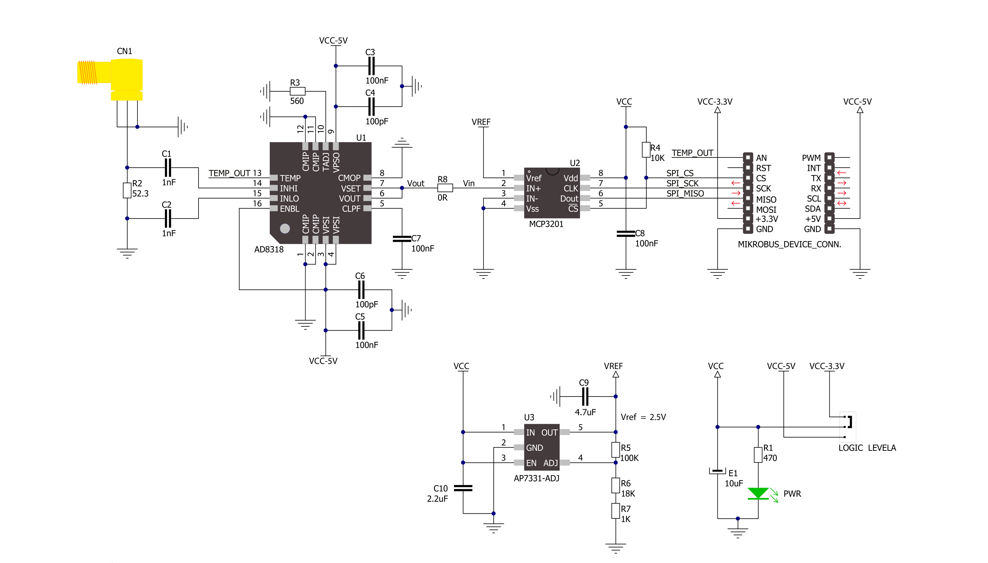
RF Meter Click is based on the AD8318, a logarithmic detector/controller from Analog Devices. It is a demodulating logarithmic amplifier capable of accurately converting an RF input signal to a corresponding decibel-scaled output voltage. It employs the progressive compression technique over a cascaded amplifier chain, with each stage equipped with a detector cell. The AD8318 can be used in measurement or controller mode of operation. It maintains accurate log conformance for signals of 1MHz to 6GHz and provides operation up to 8GHz. The input range is typically 60dB with an error of less than ±1dB and a 10ns response time that enables RF burst
detection beyond 45MHz. In addition, the AD8318 comes with an integrated temperature sensor with independent output, which can be used for temperature compensation. The voltage output of the AD8318 goes to the MCP3201, a successive approximation 12-bit analog-to-digital converter with an onboard sample and hold circuitry from Microchip. This ADC provides a single pseudo-differential output, with sample rates of up to 100ksps. To provide correct values, this Click board™ uses an AP7331 LDO linear regulator to provide referent voltage to the MCP3201. The RF Meter uses a 3-wire SPI serial interface of the MCP3201 to communicate to the host MCU
over the mikroBUS™ socket. The RF Meter can use either an SPI mode 0 or an SPI mode 1, depending on the needs. The readings of the independent temperature sensor of the AD8318 can be read over the OUT pin mikroBUS™ socket, giving analog values. This Click board™ can operate with either 3.3V or 5V logic voltage levels selected via the LOGIC LEVEL jumper. This way, both 3.3V and 5V capable MCUs can use the communication lines properly. Also, this Click board™ comes equipped with a library containing easy-to-use functions and an example code that can be used as a reference for further development.

Features overview
Development board
Arduino UNO is a versatile microcontroller board built around the ATmega328P chip. It offers extensive connectivity options for various projects, featuring 14 digital input/output pins, six of which are PWM-capable, along with six analog inputs. Its core components include a 16MHz ceramic resonator, a USB connection, a power jack, an
ICSP header, and a reset button, providing everything necessary to power and program the board. The Uno is ready to go, whether connected to a computer via USB or powered by an AC-to-DC adapter or battery. As the first USB Arduino board, it serves as the benchmark for the Arduino platform, with "Uno" symbolizing its status as the
first in a series. This name choice, meaning "one" in Italian, commemorates the launch of Arduino Software (IDE) 1.0. Initially introduced alongside version 1.0 of the Arduino Software (IDE), the Uno has since become the foundational model for subsequent Arduino releases, embodying the platform's evolution.

Microcontroller Overview
MCU Card / MCU

Architecture
AVR
MCU Memory (KB)
32
Silicon Vendor
Microchip
Pin count
28
RAM (Bytes)
2048
You complete me!
Accessories
Click Shield for Arduino UNO has two proprietary mikroBUS™ sockets, allowing all the Click board™ devices to be interfaced with the Arduino UNO board without effort. The Arduino Uno, a microcontroller board based on the ATmega328P, provides an affordable and flexible way for users to try out new concepts and build prototypes with the ATmega328P microcontroller from various combinations of performance, power consumption, and features. The Arduino Uno has 14 digital input/output pins (of which six can be used as PWM outputs), six analog inputs, a 16 MHz ceramic resonator (CSTCE16M0V53-R0), a USB connection, a power jack, an ICSP header, and reset button. Most of the ATmega328P microcontroller pins are brought to the IO pins on the left and right edge of the board, which are then connected to two existing mikroBUS™ sockets. This Click Shield also has several switches that perform functions such as selecting the logic levels of analog signals on mikroBUS™ sockets and selecting logic voltage levels of the mikroBUS™ sockets themselves. Besides, the user is offered the possibility of using any Click board™ with the help of existing bidirectional level-shifting voltage translators, regardless of whether the Click board™ operates at a 3.3V or 5V logic voltage level. Once you connect the Arduino UNO board with our Click Shield for Arduino UNO, you can access hundreds of Click boards™, working with 3.3V or 5V logic voltage levels.

Used MCU Pins
mikroBUS™ mapper
Take a closer look
Click board™ Schematic
Step by step
Project assembly

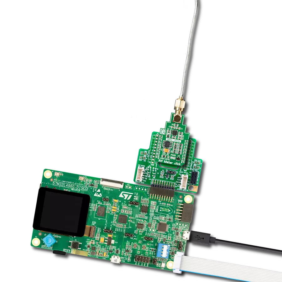
Start by selecting your development board and Click board™. Begin with the Arduino UNO Rev3 as your development board.


Software Support
Library Description
This library contains API for RF Meter Click driver.
Key functions:
rfmeter_get_signal_strenght- Function is used to calculate radio frequency signal strenght in a vicinity
Open Source
Code example
The complete application code and a ready-to-use project are available through the NECTO Studio Package Manager for direct installation in the NECTO Studio. The application code can also be found on the MIKROE GitHub account.
/*!
 * \file
 * \brief Rfmeter Click example
 *
 * # Description
 * Demo app measures and displays signal strenght by using RF Meter Click board.
 *
 * The demo application is composed of two sections :
 *
 * ## Application Init
 * Initalizes SPI, LOG and Click drivers.
 *
 * ## Application Task
 * This is an example that shows the capabilities of the RF Meter Click by
 * measuring radio frequency signal strenght.
 *
 * \author Jovan Stajkovic
 *
 */
// ------------------------------------------------------------------- INCLUDES

#include "board.h"
#include "log.h"
#include "rfmeter.h"

// ------------------------------------------------------------------ VARIABLES

static rfmeter_t rfmeter;
static log_t logger;
static float signal;

// ------------------------------------------------------- ADDITIONAL FUNCTIONS


// ------------------------------------------------------ APPLICATION FUNCTIONS

void application_init ( void )
{
    log_cfg_t log_cfg;
    rfmeter_cfg_t cfg;

    /**
     * Logger initialization.
     * Default baud rate: 115200
     * Default log level: LOG_LEVEL_DEBUG
     * @note If USB_UART_RX and USB_UART_TX
     * are defined as HAL_PIN_NC, you will
     * need to define them manually for log to work.
     * See @b LOG_MAP_USB_UART macro definition for detailed explanation.
     */
    LOG_MAP_USB_UART( log_cfg );
    log_init( &logger, &log_cfg );
    log_info( &logger, "---- Application Init ----" );

    //  Click initialization.

    rfmeter_cfg_setup( &cfg );
    RFMETER_MAP_MIKROBUS( cfg, MIKROBUS_1 );
    rfmeter_init( &rfmeter, &cfg );
    log_printf( &logger, "----------------------- \r\n" );
    log_printf( &logger, "    RF Meter Click      \r\n" );
    log_printf( &logger, "----------------------- \r\n" );
}

void application_task ( void )
{
    signal = rfmeter_get_signal_strenght( &rfmeter, RFMETER_DEF_SLOPE, RFMETER_DEF_INTERCEPT );

    log_printf( &logger, "Signal strenght: %.2f dBm \r\n", signal );

    Delay_ms ( 1000 );
    log_printf( &logger, "-----------------------\r\n" );
}

int main ( void )
{
    /* Do not remove this line or clock might not be set correctly. */
    #ifdef PREINIT_SUPPORTED
    preinit();
    #endif

    application_init( );

    for ( ; ; )
    {
        application_task( );
    }

    return 0;
}


// ------------------------------------------------------------------------ END
Additional Support
Resources
Category:RF meter