Navigate with ease using our LED-encircled rotary solution based on the EC12D1564402 and ATmega328
Go green, go rotary!
Published Feb 14, 2024
Click board™
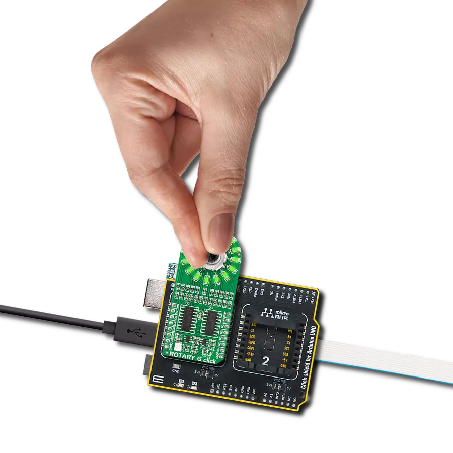
ROTARY G Click
Dev. board
Arduino UNO Rev3
Compiler
NECTO Studio
MCU
ATmega328
Elevate your experience with our revolutionary rotary solution, guided by a luminous green LED circle of trust
A
A
Hardware Overview
How does it work?
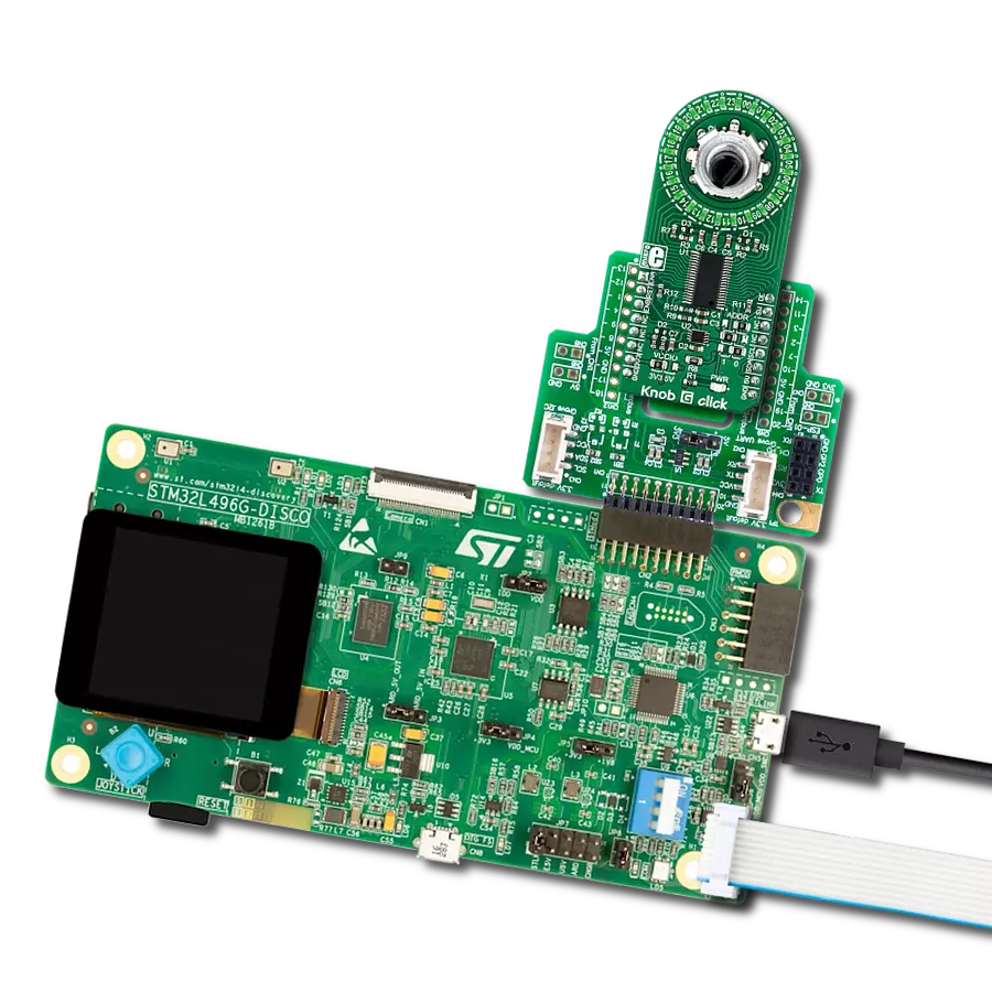
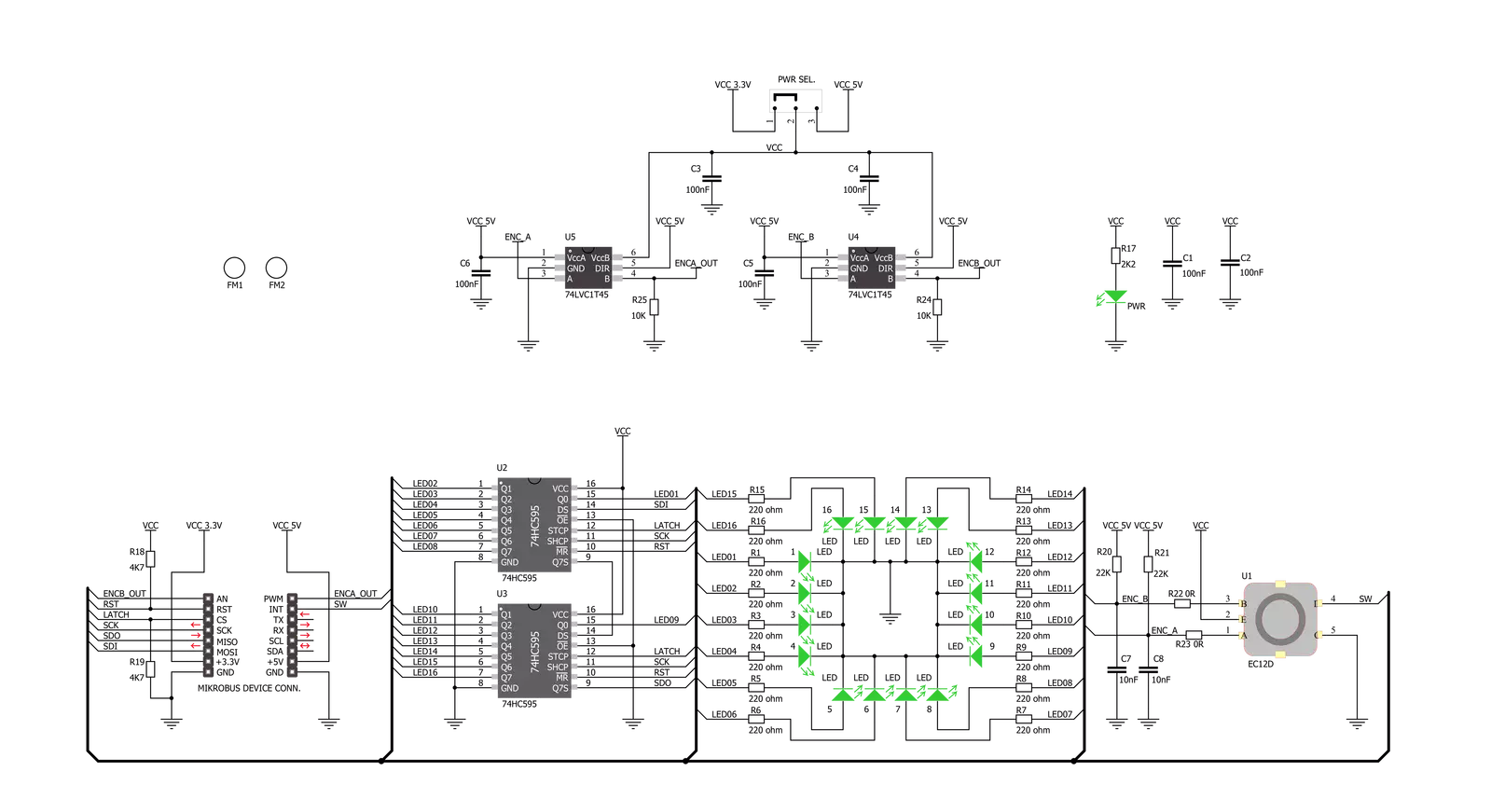
ROTARY G Click is based on two SN74HC595 SPI-configurable 8-bit shift registers from Texas Instruments that, combined with a high-quality rotary encoder, the EC12D1564402, allows you to add a precision input knob to your design. The EC12D1564402 incremental rotary encoder is surrounded by a ring of 16 green LEDs where a single rotation is divided into 15 discrete steps (in contrast to a potentiometer, a rotary encoder can be spun around continuously). This Click board™ is an ideal solution for building various HMI applications where precise input is required, but also for some interesting visual effects to any application. As mentioned, this Click board™ uses
the EC12D1564402, a 15-pulse incremental rotary encoder with a push-button, from ALPS. This encoder has unique mechanical specifications (debouncing time for its internal switches goes down to 2ms) and can withstand many switching cycles, up to 30.000. The supporting debouncing circuitry allows contacts to settle before the output is triggered fully. The SN74HC595 controls each LED individually positioned in a ring around the encoder through a standard SPI interface with a maximum frequency of 5MHz. Rotating the encoder, it outputs A and B signals (out of phase to each other) on the two mikroBUS™ lines, AN and PWM pins of the mikroBUS™ socket,
alongside the push-button contact, which outputs through the interrupt line of the mikroBUS™ socket. The SN74HC595 also has a Reset feature used across the RST mikroBUS™ line. This Click board™ can operate with both 3.3V and 5V logic voltage levels selected via the PWR SEL jumper. This way, it is allowed for both 3.3V and 5V capable MCUs to use the communication lines properly. However, the Click board™ comes equipped with a library containing easy-to-use functions and an example code that can be used, as a reference, for further development.

Features overview
Development board
Arduino UNO is a versatile microcontroller board built around the ATmega328P chip. It offers extensive connectivity options for various projects, featuring 14 digital input/output pins, six of which are PWM-capable, along with six analog inputs. Its core components include a 16MHz ceramic resonator, a USB connection, a power jack, an
ICSP header, and a reset button, providing everything necessary to power and program the board. The Uno is ready to go, whether connected to a computer via USB or powered by an AC-to-DC adapter or battery. As the first USB Arduino board, it serves as the benchmark for the Arduino platform, with "Uno" symbolizing its status as the
first in a series. This name choice, meaning "one" in Italian, commemorates the launch of Arduino Software (IDE) 1.0. Initially introduced alongside version 1.0 of the Arduino Software (IDE), the Uno has since become the foundational model for subsequent Arduino releases, embodying the platform's evolution.

Microcontroller Overview
MCU Card / MCU

Architecture
AVR
MCU Memory (KB)
32
Silicon Vendor
Microchip
Pin count
32
RAM (Bytes)
2048
You complete me!
Accessories
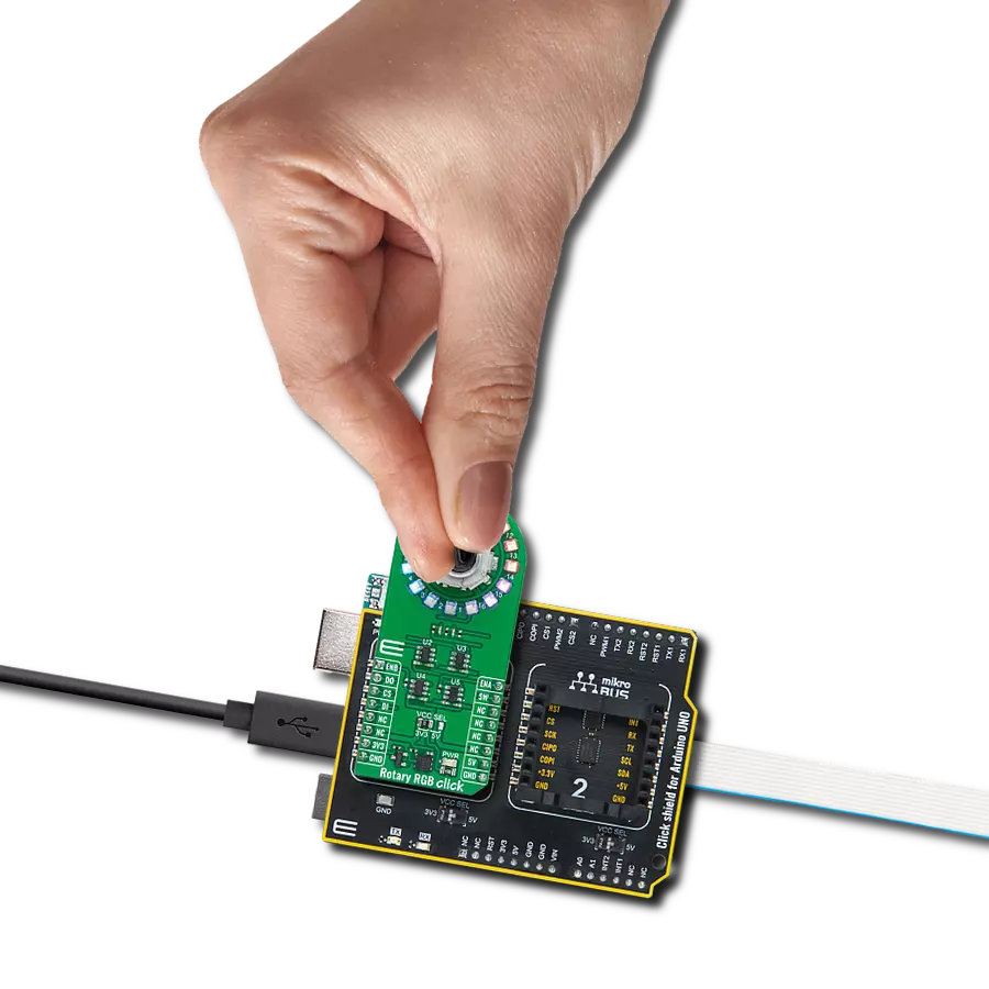
Click Shield for Arduino UNO has two proprietary mikroBUS™ sockets, allowing all the Click board™ devices to be interfaced with the Arduino UNO board without effort. The Arduino Uno, a microcontroller board based on the ATmega328P, provides an affordable and flexible way for users to try out new concepts and build prototypes with the ATmega328P microcontroller from various combinations of performance, power consumption, and features. The Arduino Uno has 14 digital input/output pins (of which six can be used as PWM outputs), six analog inputs, a 16 MHz ceramic resonator (CSTCE16M0V53-R0), a USB connection, a power jack, an ICSP header, and reset button. Most of the ATmega328P microcontroller pins are brought to the IO pins on the left and right edge of the board, which are then connected to two existing mikroBUS™ sockets. This Click Shield also has several switches that perform functions such as selecting the logic levels of analog signals on mikroBUS™ sockets and selecting logic voltage levels of the mikroBUS™ sockets themselves. Besides, the user is offered the possibility of using any Click board™ with the help of existing bidirectional level-shifting voltage translators, regardless of whether the Click board™ operates at a 3.3V or 5V logic voltage level. Once you connect the Arduino UNO board with our Click Shield for Arduino UNO, you can access hundreds of Click boards™, working with 3.3V or 5V logic voltage levels.

Used MCU Pins
mikroBUS™ mapper
Take a closer look
Click board™ Schematic
Step by step
Project assembly

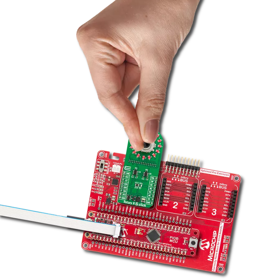
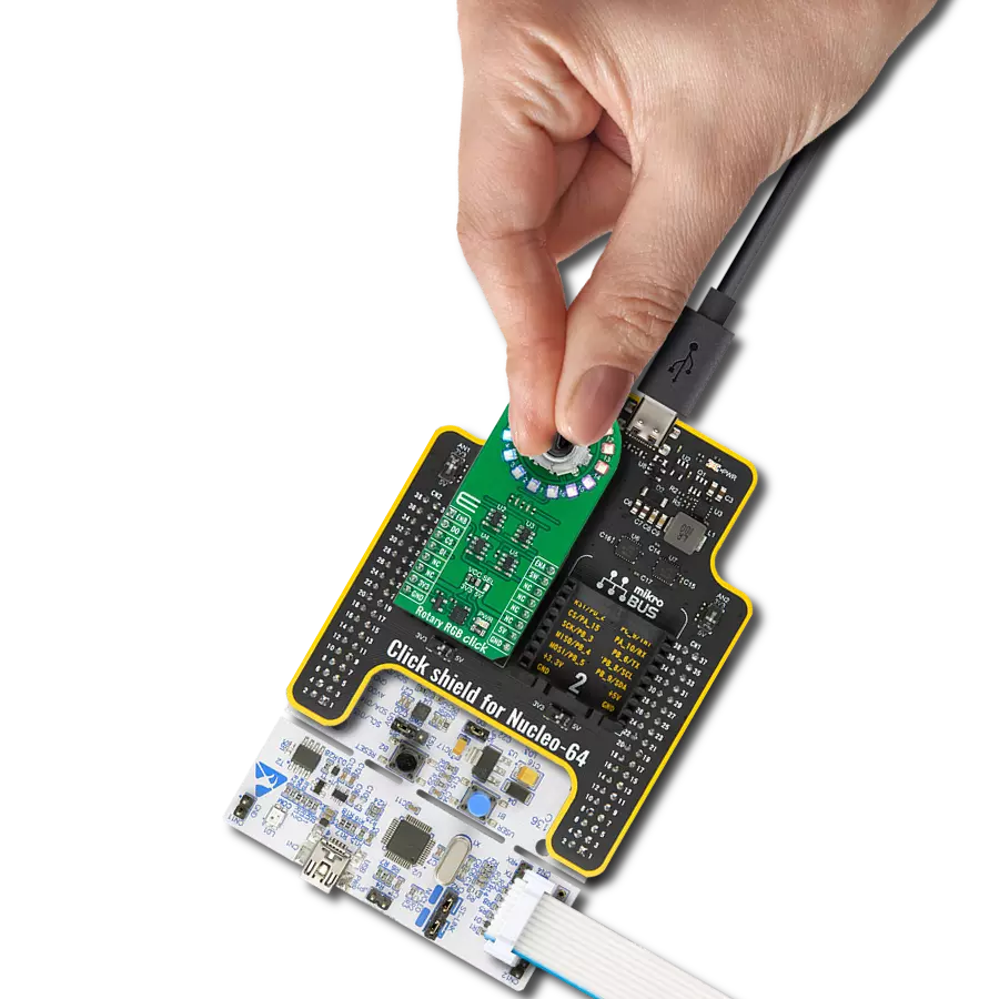
Start by selecting your development board and Click board™. Begin with the Arduino UNO Rev3 as your development board.


Track your results in real time
Application Output
1. Application Output - In Debug mode, the 'Application Output' window enables real-time data monitoring, offering direct insight into execution results. Ensure proper data display by configuring the environment correctly using the provided tutorial.

2. UART Terminal - Use the UART Terminal to monitor data transmission via a USB to UART converter, allowing direct communication between the Click board™ and your development system. Configure the baud rate and other serial settings according to your project's requirements to ensure proper functionality. For step-by-step setup instructions, refer to the provided tutorial.

3. Plot Output - The Plot feature offers a powerful way to visualize real-time sensor data, enabling trend analysis, debugging, and comparison of multiple data points. To set it up correctly, follow the provided tutorial, which includes a step-by-step example of using the Plot feature to display Click board™ readings. To use the Plot feature in your code, use the function: plot(*insert_graph_name*, variable_name);. This is a general format, and it is up to the user to replace 'insert_graph_name' with the actual graph name and 'variable_name' with the parameter to be displayed.

Software Support
Library Description
This library contains API for ROTARY G Click driver.
Key functions:
rotaryg_generic_transfer- ROTARY G data transfer function.rotaryg_turn_on_led_by_position- Function turn on led by positionrotaryg_button_push- Function return 1 if button is pushed and return 0 if not
Open Source
Code example
The complete application code and a ready-to-use project are available through the NECTO Studio Package Manager for direct installation in the NECTO Studio. The application code can also be found on the MIKROE GitHub account.
/*!
 * @file main.c
 * @brief Rotary G Click example
 *
 * # Description
 * The demo application controls led on Click with rotary on board.
 *
 * The demo application is composed of two sections :
 *
 * ## Application Init
 * Initializes SPI driver, set initial states,
 * set RST logic high and performs device configuration.
 *
 * ## Application Task
 * Show functionality of Rotary G Click, rotating and turn on/off led's,
 * using the SPI interface.
 *
 * @note
 * In orther to use all of the Clicks functionality, pull down INT pin.
 *
 * @author Stefan Ilic
 *
 */

#include "board.h"
#include "log.h"
#include "rotaryg.h"

static rotaryg_t rotaryg;
static log_t logger;

static uint8_t start_status;
static uint8_t old_state;
static uint8_t new_state;
static uint8_t old__rot_state;
static uint8_t new_rotate_state;
static uint8_t led_state;
static uint16_t led_data;

void application_init ( void ) {
    log_cfg_t log_cfg;  /**< Logger config object. */
    rotaryg_cfg_t rotaryg_cfg;  /**< Click config object. */

    /**
     * Logger initialization.
     * Default baud rate: 115200
     * Default log level: LOG_LEVEL_DEBUG
     * @note If USB_UART_RX and USB_UART_TX
     * are defined as HAL_PIN_NC, you will
     * need to define them manually for log to work.
     * See @b LOG_MAP_USB_UART macro definition for detailed explanation.
     */
    LOG_MAP_USB_UART( log_cfg );
    log_init( &logger, &log_cfg );
    log_info( &logger, " Application Init " );

    // Click initialization.

    rotaryg_cfg_setup( &rotaryg_cfg );
    ROTARYG_MAP_MIKROBUS( rotaryg_cfg, MIKROBUS_1 );
    err_t init_flag  = rotaryg_init( &rotaryg, &rotaryg_cfg );
    if ( init_flag == SPI_MASTER_ERROR ) {
        log_error( &logger, " Application Init Error. " );
        log_info( &logger, " Please, run program again... " );

        for ( ; ; );
    }

    log_info( &logger, " Application Task " );

    led_data = 0x0001;
    old_state = 0;
    new_state = 1;
    old__rot_state = 0;
    new_rotate_state = 1;
}

void application_task ( void ) {
   rotaryg_turn_on_led_by_data( &rotaryg, led_data );

   // Push button
    if ( rotaryg_button_push( &rotaryg ) ) {
        new_state = 1;
        if ( new_state == 1 && old_state == 0 ) {
            old_state = 1;
            led_state = ( led_state + 1 ) % 5;
            if ( led_state == 4 ) {
                for ( old_state = 0; old_state < 17; old_state++ ) {
                    rotaryg_turn_on_led_by_data( &rotaryg, 0xAAAA );
                    Delay_ms ( 100 );
                    rotaryg_turn_on_led_by_data( &rotaryg, 0x5555 );
                    Delay_ms ( 100 );
                }

                for ( old_state = 0; old_state < 17; old_state++ ) {
                    rotaryg_turn_on_led_by_position( &rotaryg, old_state );
                    Delay_ms ( 100 );
                }

                led_state = 0;
                led_data = rotaryg_get_led_data( led_state );
            }
            else {
                led_data = rotaryg_get_led_data( led_state );
            }
        }
    }
    else {
        old_state = 0;
    }

    //Rotate Clockwise and CounterClockwise
    if ( rotaryg_get_eca_state( &rotaryg ) == rotaryg_get_ecb_state( &rotaryg ) ) {
        old__rot_state = 0;
        start_status = rotaryg_get_eca_state( &rotaryg ) && rotaryg_get_ecb_state( &rotaryg );
    }
    else {
        new_rotate_state = 1;
        if ( new_rotate_state != old__rot_state ) {
            old__rot_state = 1;
            if ( start_status != rotaryg_get_eca_state( &rotaryg ) ) {
                led_data = ( led_data << 1 ) | ( led_data >> 15 );
            }
            else {
                led_data = ( led_data >> 1 ) | ( led_data << 15 );
            }
        }
    }
}

int main ( void )
{
    /* Do not remove this line or clock might not be set correctly. */
    #ifdef PREINIT_SUPPORTED
    preinit();
    #endif

    application_init( );

    for ( ; ; )
    {
        application_task( );
    }

    return 0;
}

// ------------------------------------------------------------------------ END
Additional Support
Resources
Category:Rotary encoder