Master the art of movement and give your projects the finesse they deserve, thanks to TB67S580FNG and ATmega328
Infinite steps, one solution: Elevate with our stepper driver

Published Feb 14, 2024
Click board™
Stepper 20 Click
Dev. board
Arduino UNO Rev3
Compiler
NECTO Studio
MCU
ATmega328
Break free from limitations and explore limitless possibilities in motion control with our intelligent stepper motor driver solution, engineered for excellence.
A
A
Hardware Overview
How does it work?
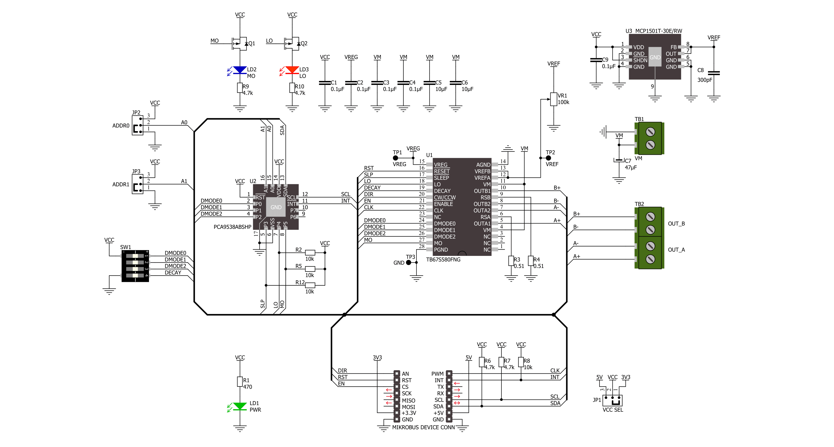
Stepper 20 Click is based on the TB67S580FNG, a two-phase bipolar stepping motor driver designed to control one bipolar stepping motor from Toshiba Semiconductor. The TB67S580FNG supports a PWM constant-current control drive and incorporates low on-resistance DMOS FETs, delivering a 1.28A maximum current. It can also provide a motor output voltage rating of around 40V and has integrated protection mechanisms such as over-current, over-temperature, and under-voltage lockout for error detection (red LO LED indicator). It supports full-step to 1/32 steps resolution for less motor noise and smoother control, with a built-in regulator that allows the motor to be driven by a single power supply. The current value in the PWM constant-current mode is set by the reference voltage obtained by the MCP1501, a high-precision voltage regulator. Also, the current threshold point of the TB67S580FNG, alongside MCP1501, can be set manually using an onboard trimmer labeled VREF. The TB67S580FNG supports various step resolution configurations through its control signals. These
signals, like step resolution settings, sleep mode, or LO/MO indicators, are controlled through the PCA9538A port expander, which establishes communication with the MCU via the I2C serial interface. In addition to this digital way of setting, these functions can also be selected manually via a multifunctional switch by selecting a particular switch (1,2,3 – Step Resolution Setting; 4 - Decay Mode Control). The PCA9538A also allows choosing the least significant bit (LSB) of its I2C slave address by positioning SMD jumpers labeled as ADDR SEL to an appropriate position marked as 0 and 1, alongside its interrupt feature routed to the INT pin of the mikroBUS™ socket. The CLK clock signal, routed to the default PWM position on the mikroBUS™ socket, shifts the current step and electrical angle of the motor with its every up-edge, while the Enable pin, labeled as EN and routed to the default CS position, controls the state of the output A and B stepping motor drive channels. Besides, all circuits can be stopped using the Sleep function and thus enable power saving mode. A simple DIR pin routed to the
default AN position on the mikroBUS™ socket allows MCU to manage the direction of the stepper motor (clockwise or counterclockwise) while the RST pin initializes an electrical angle in the internal counter to set an initial position. Achieving an initial electrical angle position is indicated via an onboard orange LED labeled as MO. The Stepper 20 Click supports an external power supply for the TB67S580FNG, which can be connected to the input terminal labeled as VM and should be within the range of 8.2V to 44V, while the stepper motor coils can be connected to the terminals labeled as B+, B-, A-, and A+. This Click board™ can operate with either 3.3V or 5V logic voltage levels selected via the VCC SEL jumper. This way, both 3.3V and 5V capable MCUs can use the communication lines properly. Also, this Click board™ comes equipped with a library containing easy-to-use functions and an example code that can be used as a reference for further development.

Features overview
Development board
Arduino UNO is a versatile microcontroller board built around the ATmega328P chip. It offers extensive connectivity options for various projects, featuring 14 digital input/output pins, six of which are PWM-capable, along with six analog inputs. Its core components include a 16MHz ceramic resonator, a USB connection, a power jack, an
ICSP header, and a reset button, providing everything necessary to power and program the board. The Uno is ready to go, whether connected to a computer via USB or powered by an AC-to-DC adapter or battery. As the first USB Arduino board, it serves as the benchmark for the Arduino platform, with "Uno" symbolizing its status as the
first in a series. This name choice, meaning "one" in Italian, commemorates the launch of Arduino Software (IDE) 1.0. Initially introduced alongside version 1.0 of the Arduino Software (IDE), the Uno has since become the foundational model for subsequent Arduino releases, embodying the platform's evolution.

Microcontroller Overview
MCU Card / MCU

Architecture
AVR
MCU Memory (KB)
32
Silicon Vendor
Microchip
Pin count
32
RAM (Bytes)
2048
You complete me!
Accessories
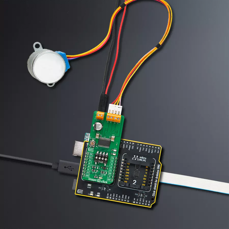
Click Shield for Arduino UNO has two proprietary mikroBUS™ sockets, allowing all the Click board™ devices to be interfaced with the Arduino UNO board without effort. The Arduino Uno, a microcontroller board based on the ATmega328P, provides an affordable and flexible way for users to try out new concepts and build prototypes with the ATmega328P microcontroller from various combinations of performance, power consumption, and features. The Arduino Uno has 14 digital input/output pins (of which six can be used as PWM outputs), six analog inputs, a 16 MHz ceramic resonator (CSTCE16M0V53-R0), a USB connection, a power jack, an ICSP header, and reset button. Most of the ATmega328P microcontroller pins are brought to the IO pins on the left and right edge of the board, which are then connected to two existing mikroBUS™ sockets. This Click Shield also has several switches that perform functions such as selecting the logic levels of analog signals on mikroBUS™ sockets and selecting logic voltage levels of the mikroBUS™ sockets themselves. Besides, the user is offered the possibility of using any Click board™ with the help of existing bidirectional level-shifting voltage translators, regardless of whether the Click board™ operates at a 3.3V or 5V logic voltage level. Once you connect the Arduino UNO board with our Click Shield for Arduino UNO, you can access hundreds of Click boards™, working with 3.3V or 5V logic voltage levels.

The 28BYJ-48 is an adaptable 5VDC stepper motor with a compact design, ideal for various applications. It features four phases, a speed variation ratio of 1/64, and a stride angle of 5.625°/64 steps, allowing precise control. The motor operates at a frequency of 100Hz and has a DC resistance of 50Ω ±7% at 25°C. It boasts an idle in-traction frequency greater than 600Hz and an idle out-traction frequency exceeding 1000Hz, ensuring reliability in different scenarios. With a self-positioning torque and in-traction torque both exceeding 34.3mN.m at 120Hz, the 28BYJ-48 offers robust performance. Its friction torque ranges from 600 to 1200 gf.cm, while the pull-in torque is 300 gf.cm. This motor makes a reliable and efficient choice for your stepper motor needs.

Used MCU Pins
mikroBUS™ mapper
Take a closer look
Click board™ Schematic
Step by step
Project assembly

Start by selecting your development board and Click board™. Begin with the Arduino UNO Rev3 as your development board.


Track your results in real time
Application Output
1. Application Output - In Debug mode, the 'Application Output' window enables real-time data monitoring, offering direct insight into execution results. Ensure proper data display by configuring the environment correctly using the provided tutorial.

2. UART Terminal - Use the UART Terminal to monitor data transmission via a USB to UART converter, allowing direct communication between the Click board™ and your development system. Configure the baud rate and other serial settings according to your project's requirements to ensure proper functionality. For step-by-step setup instructions, refer to the provided tutorial.

3. Plot Output - The Plot feature offers a powerful way to visualize real-time sensor data, enabling trend analysis, debugging, and comparison of multiple data points. To set it up correctly, follow the provided tutorial, which includes a step-by-step example of using the Plot feature to display Click board™ readings. To use the Plot feature in your code, use the function: plot(*insert_graph_name*, variable_name);. This is a general format, and it is up to the user to replace 'insert_graph_name' with the actual graph name and 'variable_name' with the parameter to be displayed.

Software Support
Library Description
This library contains API for Stepper 20 Click driver.
Key functions:
stepper20_set_direction- This function sets the motor direction by setting the DIR pin logic state.stepper20_drive_motor- This function drives the motor for the specific number of steps at the selected speed.stepper20_set_step_mode- This function sets the step mode resolution settings.
Open Source
Code example
The complete application code and a ready-to-use project are available through the NECTO Studio Package Manager for direct installation in the NECTO Studio. The application code can also be found on the MIKROE GitHub account.
/*!
 * @file main.c
 * @brief Stepper 20 Click example
 *
 * # Description
 * This example demonstrates the use of the Stepper 20 Click board by driving the
 * motor in both directions for a desired number of steps.
 *
 * The demo application is composed of two sections :
 *
 * ## Application Init
 * Initializes the driver and performs the Click default configuration.
 *
 * ## Application Task
 * Drives the motor clockwise for 200 full steps and then counter-clockiwse for 400 quarter
 * steps with 2 seconds delay before changing the direction. All data is being logged on
 * the USB UART where you can track the program flow.
 *
 * @author Stefan Filipovic
 *
 */

#include "board.h"
#include "log.h"
#include "stepper20.h"

static stepper20_t stepper20;
static log_t logger;

void application_init ( void )
{
    log_cfg_t log_cfg;  /**< Logger config object. */
    stepper20_cfg_t stepper20_cfg;  /**< Click config object. */

    /**
     * Logger initialization.
     * Default baud rate: 115200
     * Default log level: LOG_LEVEL_DEBUG
     * @note If USB_UART_RX and USB_UART_TX
     * are defined as HAL_PIN_NC, you will
     * need to define them manually for log to work.
     * See @b LOG_MAP_USB_UART macro definition for detailed explanation.
     */
    LOG_MAP_USB_UART( log_cfg );
    log_init( &logger, &log_cfg );
    log_info( &logger, " Application Init " );

    // Click initialization.
    stepper20_cfg_setup( &stepper20_cfg );
    STEPPER20_MAP_MIKROBUS( stepper20_cfg, MIKROBUS_1 );
    if ( I2C_MASTER_ERROR == stepper20_init( &stepper20, &stepper20_cfg ) )
    {
        log_error( &logger, " Communication init." );
        for ( ; ; );
    }

    if ( STEPPER20_ERROR == stepper20_default_cfg ( &stepper20 ) )
    {
        log_error( &logger, " Default configuration." );
        for ( ; ; );
    }

    log_info( &logger, " Application Task " );
}

void application_task ( void )
{
    log_printf ( &logger, " Move 200 full steps clockwise \r\n\n" );
    stepper20_set_step_mode ( &stepper20, STEPPER20_MODE_FULL_STEP );
    stepper20_set_direction ( &stepper20, STEPPER20_DIR_CW );
    stepper20_drive_motor ( &stepper20, 200, STEPPER20_SPEED_FAST );
    Delay_ms ( 1000 );
    Delay_ms ( 1000 );

    log_printf ( &logger, " Move 400 quarter steps counter-clockwise \r\n\n" );
    stepper20_set_step_mode ( &stepper20, STEPPER20_MODE_QUARTER_STEP );
    stepper20_set_direction ( &stepper20, STEPPER20_DIR_CCW );
    stepper20_drive_motor ( &stepper20, 400, STEPPER20_SPEED_VERY_FAST );
    Delay_ms ( 1000 );
    Delay_ms ( 1000 );
}

int main ( void )
{
    /* Do not remove this line or clock might not be set correctly. */
    #ifdef PREINIT_SUPPORTED
    preinit();
    #endif

    application_init( );

    for ( ; ; )
    {
        application_task( );
    }

    return 0;
}

// ------------------------------------------------------------------------ END
Additional Support
Resources
Category:Stepper


