Unlock the magic of motion with BMI323 and ATmega2560
The future of orientation: Elevate your projects with 6DOF IMU
Published Feb 14, 2024
Click board™
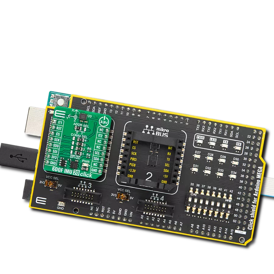
6DOF IMU 20 Click
Dev. board
Arduino Mega 2560 Rev3
Compiler
NECTO Studio
MCU
ATmega2560
Explore new realms of motion control and orientation sensing for applications where precision is paramount
A
A
Hardware Overview
How does it work?
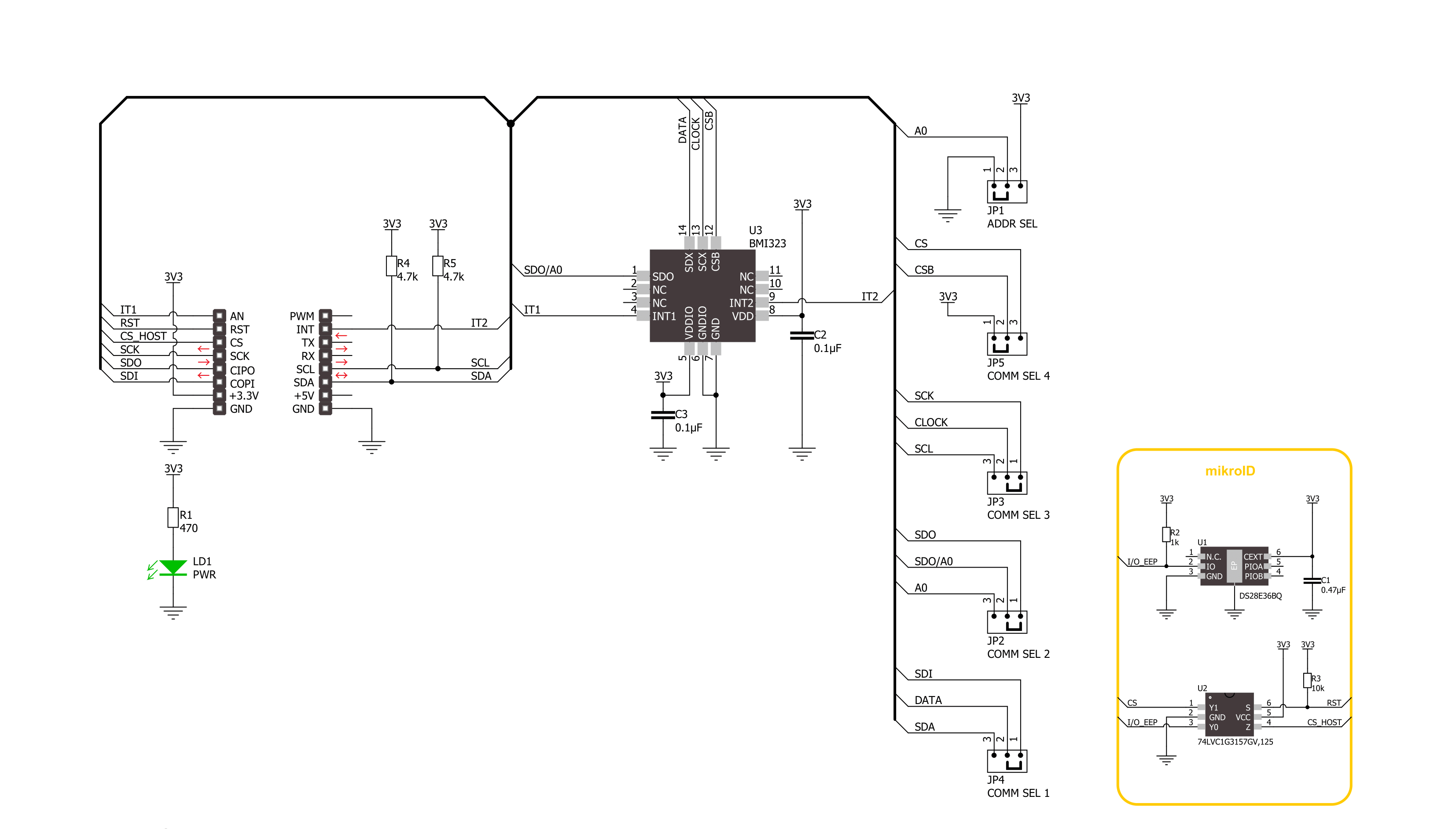
6DOF IMU 20 Click is based on the BMI323, a versatile 6DoF (six degrees of freedom) sensor module from Bosch Sensortec. This IMU combines precise acceleration and angular rate (gyroscopic) measurement with intelligent integrated features triggered by motion. It also has a 2K-byte FIFO that can lower the traffic on the selected serial bus interface by allowing the system processor to burst read sensor data. The BMI323 provides improved accelerometer performance as well as lower power consumption. In high-performance mode, using both the gyroscope and the accelerometer, the BMI323 shows a significant reduction in power consumption of nearly 15% compared to its predecessor, the BMI160. The BMI323 supports various use cases, allowing customers to design it into various applications like angle and position detection, motion detection, tap recognition, and more. The BMI323
comprises a 16-bit triaxial gyroscope, a 16-bit triaxial accelerometer, and a 16-bit digital temperature sensor in a single package. The accelerometer measures the direction and magnitude of the force applied to the sensor. In a free fall scenario, an accelerometer will report a vector of zeros. The gyroscope measures the rotational rate and reports vector zeros when the device rests. The gyroscope supports full-scale range settings from ±125dps to ±2000dps, and the accelerometer supports range settings from ±2g to ±16g. In addition, the BMI323 also includes an auxiliary temperature sensor. This Click board™ allows the use of both I2C and SPI interfaces at a maximum frequency of 1MHz for I2C and 10MHz for SPI communication. Selection is made by positioning SMD jumpers marked COMM SEL to the appropriate position. All jumpers must be on the same side, or the Click board™ may become
unresponsive. When the I2C interface is selected, the BMI323 allows the choice of its I2C slave address, using the ADDR SEL SMD jumper set to an appropriate position marked 1 or 0. In addition to communication pins, this board also possesses two interrupts, IT1 and IT2, routed to, where by default, the AN and INT pins stand on the mikroBUS™ socket, entirely programmed by the user through a serial interface. They signal MCU that a motion event has been sensed. This Click board™ can be operated only with a 3.3V logic voltage level. The board must perform appropriate logic voltage level conversion before using MCUs with different logic levels. Also, it comes equipped with a library containing functions and an example code that can be used as a reference for further development.


Features overview
Development board
Arduino Mega 2560 is a robust microcontroller platform built around the ATmega 2560 chip. It has extensive capabilities and boasts 54 digital input/output pins, including 15 PWM outputs, 16 analog inputs, and 4 UARTs. With a 16MHz crystal
oscillator ensuring precise timing, it offers seamless connectivity via USB, a convenient power jack, an ICSP header, and a reset button. This all-inclusive board simplifies microcontroller projects; connect it to your computer via USB or power it up
using an AC-to-DC adapter or battery. Notably, the Mega 2560 maintains compatibility with a wide range of shields crafted for the Uno, Duemilanove, or Diecimila boards, ensuring versatility and ease of integration.

Microcontroller Overview
MCU Card / MCU

Architecture
AVR
MCU Memory (KB)
256
Silicon Vendor
Microchip
Pin count
100
RAM (Bytes)
8192
You complete me!
Accessories
Click Shield for Arduino Mega comes equipped with four mikroBUS™ sockets, with two in the form of a Shuttle connector, allowing all the Click board™ devices to be interfaced with the Arduino Mega board with no effort. Featuring an AVR 8-bit microcontroller with advanced RISC architecture, 54 digital I/O pins, and Arduino™ compatibility, the Arduino Mega board offers limitless possibilities for prototyping and creating diverse applications. This board is controlled and powered conveniently through a USB connection to program and debug the Arduino Mega board efficiently out of the box, with an additional USB cable connected to the USB B port on the board. Simplify your project development with the integrated ATmega16U2 programmer and unleash creativity using the extensive I/O options and expansion capabilities. There are eight switches, which you can use as inputs, and eight LEDs, which can be used as outputs of the MEGA2560. In addition, the shield features the MCP1501, a high-precision buffered voltage reference from Microchip. This reference is selected by default over the EXT REF jumper at the bottom of the board. You can choose an external one, as you would usually do with an Arduino Mega board. There is also a GND hook for testing purposes. Four additional LEDs are PWR, LED (standard pin D13), RX, and TX LEDs connected to UART1 (mikroBUS™ 1 socket). This Click Shield also has several switches that perform functions such as selecting the logic levels of analog signals on mikroBUS™ sockets and selecting logic voltage levels of the mikroBUS™ sockets themselves. Besides, the user is offered the possibility of using any Click board™ with the help of existing bidirectional level-shifting voltage translators, regardless of whether the Click board™ operates at a 3.3V or 5V logic voltage level. Once you connect the Arduino Mega board with Click Shield for Arduino Mega, you can access hundreds of Click boards™, working with 3.3V or 5V logic voltage levels.

Used MCU Pins
mikroBUS™ mapper
Take a closer look
Click board™ Schematic
Step by step
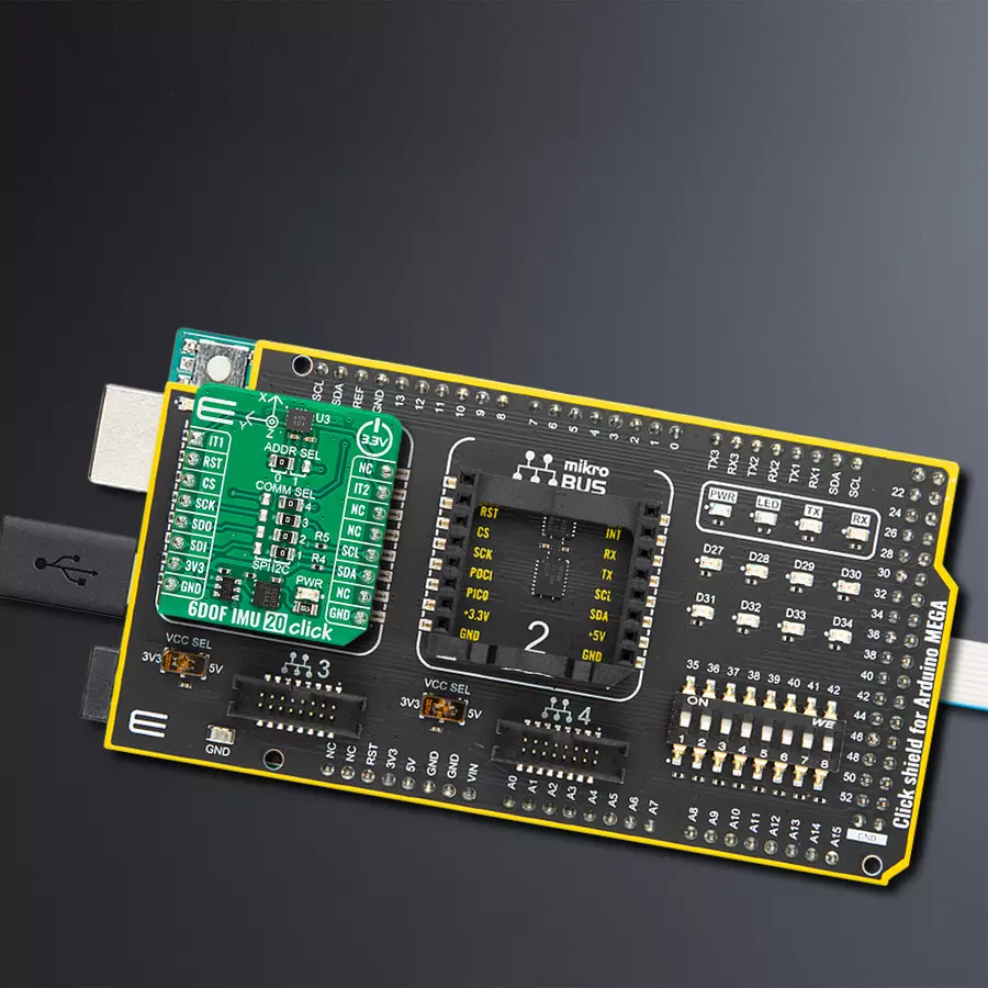
Project assembly

Start by selecting your development board and Click board™. Begin with the Arduino Mega 2560 Rev3 as your development board.


Track your results in real time
Application Output
1. Application Output - In Debug mode, the 'Application Output' window enables real-time data monitoring, offering direct insight into execution results. Ensure proper data display by configuring the environment correctly using the provided tutorial.

2. UART Terminal - Use the UART Terminal to monitor data transmission via a USB to UART converter, allowing direct communication between the Click board™ and your development system. Configure the baud rate and other serial settings according to your project's requirements to ensure proper functionality. For step-by-step setup instructions, refer to the provided tutorial.

3. Plot Output - The Plot feature offers a powerful way to visualize real-time sensor data, enabling trend analysis, debugging, and comparison of multiple data points. To set it up correctly, follow the provided tutorial, which includes a step-by-step example of using the Plot feature to display Click board™ readings. To use the Plot feature in your code, use the function: plot(*insert_graph_name*, variable_name);. This is a general format, and it is up to the user to replace 'insert_graph_name' with the actual graph name and 'variable_name' with the parameter to be displayed.

Software Support
Library Description
This library contains API for 6DOF IMU 20 Click driver.
Key functions:
c6dofimu20_get_gyr_data- 6DOF IMU 20 gyro data reading functionc6dofimu20_get_temperature- 6DOF IMU 20 temperature reading functionc6dofimu20_sw_reset- 6DOF IMU 20 software reset function
Open Source
Code example
The complete application code and a ready-to-use project are available through the NECTO Studio Package Manager for direct installation in the NECTO Studio. The application code can also be found on the MIKROE GitHub account.
/*!
 * @file main.c
 * @brief 6DOF IMU 20 Click example
 *
 * # Description
 * This library contains API for 6DOF IMU 20 Click driver.
 * The library initializes and defines the I2C and SPI bus drivers to
 * write and read data from registers, as well as the default
 * configuration for reading gyroscope and accelerator data, and temperature.
 *
 * The demo application is composed of two sections :
 *
 * ## Application Init
 * Initializes the driver after that resets the device and
 * performs default configuration and reads the device id.
 *
 * ## Application Task
 * This example demonstrates the use of the 6DOF IMU 20 Click board by
 * measuring and displaying acceleration and gyroscope data for X-axis,
 * Y-axis, and Z-axis as well as temperature in degrees Celsius.
 *
 * @author Stefan Ilic
 *
 */

#include "board.h"
#include "log.h"
#include "c6dofimu20.h"

static c6dofimu20_t c6dofimu20;
static log_t logger;

void application_init ( void )
{
    log_cfg_t log_cfg;  /**< Logger config object. */
    c6dofimu20_cfg_t c6dofimu20_cfg;  /**< Click config object. */

    /**
     * Logger initialization.
     * Default baud rate: 115200
     * Default log level: LOG_LEVEL_DEBUG
     * @note If USB_UART_RX and USB_UART_TX
     * are defined as HAL_PIN_NC, you will
     * need to define them manually for log to work.
     * See @b LOG_MAP_USB_UART macro definition for detailed explanation.
     */
    LOG_MAP_USB_UART( log_cfg );
    log_init( &logger, &log_cfg );
    log_info( &logger, " Application Init " );

    // Click initialization.
    c6dofimu20_cfg_setup( &c6dofimu20_cfg );
    C6DOFIMU20_MAP_MIKROBUS( c6dofimu20_cfg, MIKROBUS_1 );
    err_t init_flag = c6dofimu20_init( &c6dofimu20, &c6dofimu20_cfg );
    if ( ( I2C_MASTER_ERROR == init_flag ) || ( SPI_MASTER_ERROR == init_flag ) )
    {
        log_error( &logger, " Communication init." );
        for ( ; ; );
    }
    uint8_t chip_id;

    c6dofimu20_get_id( &c6dofimu20, &chip_id );
    if ( C6DOFIMU20_CHIP_ID != chip_id )
    {
        log_error( &logger, " Communication error." );
        for ( ; ; );
    }

    if ( C6DOFIMU20_ERROR == c6dofimu20_default_cfg ( &c6dofimu20 ) )
    {
        log_error( &logger, " Default configuration." );
        for ( ; ; );
    }

    log_info( &logger, " Application Task " );
}

void application_task ( void )
{
    c6dofimu20_data_t accel_data;
    c6dofimu20_data_t gyro_data;
    uint16_t data_rdy;
    float temperature;
    c6dofimu20_get_reg( &c6dofimu20, C6DOFIMU20_REG_STATUS, &data_rdy );
    if ( C6DOFIMU20_STATUS_DRDY_ACC_FLAG & data_rdy )
    {
        c6dofimu20_get_acc_data( &c6dofimu20, &accel_data );
        log_printf( &logger, " Accel: X: %d, Y: %d, Z: %d \r\n", accel_data.data_x, accel_data.data_y, accel_data.data_z );
    }
    if ( C6DOFIMU20_STATUS_DRDY_GYR_FLAG & data_rdy )
    {
        c6dofimu20_get_gyr_data( &c6dofimu20, &gyro_data );
        log_printf( &logger, " Gyro: X: %d, Y: %d, Z: %d \r\n", gyro_data.data_x, gyro_data.data_y, gyro_data.data_z );
    }
    if ( C6DOFIMU20_STATUS_DRDY_TEMP_FLAG & data_rdy )
    {
        c6dofimu20_get_temperature( &c6dofimu20, &temperature );
        log_printf( &logger, " Temperature: %.2f degC \r\n", temperature );
    }
    log_printf( &logger, " - - - - - - - - - - - - - - - - - - - - - - - - \r\n" );
    Delay_ms ( 500 );
}

int main ( void )
{
    /* Do not remove this line or clock might not be set correctly. */
    #ifdef PREINIT_SUPPORTED
    preinit();
    #endif

    application_init( );

    for ( ; ; )
    {
        application_task( );
    }

    return 0;
}

// ------------------------------------------------------------------------ END
Additional Support
Resources
Category:Motion


