Customize and manage your surroundings with ease and style using ISC15ANP4 and PIC24FV16KA304
Beyond the button

Published Nov 01, 2023
Click board™
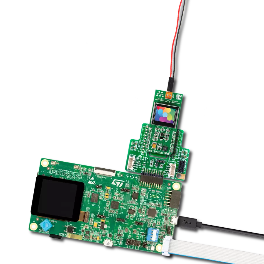
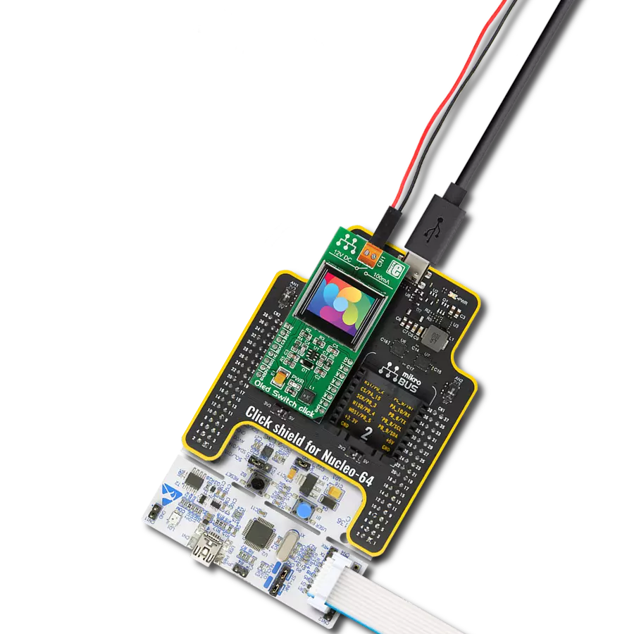
Oled Switch Click
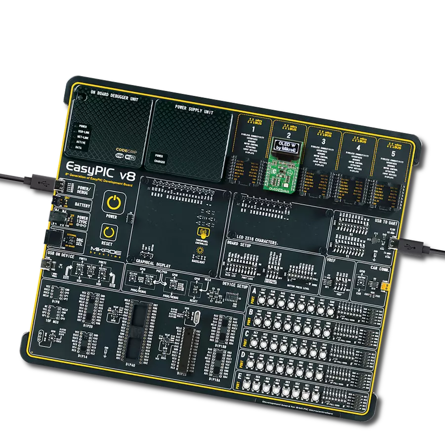
Dev. board
EasyPIC v8 for PIC24/dsPIC33
Compiler
NECTO Studio
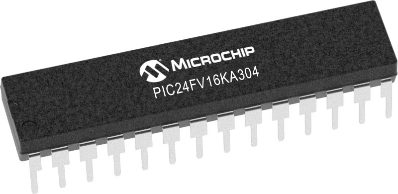
MCU
PIC24FV16KA304
Witness how this smart display reimagines the way we interact with our devices, offering a beautiful and intuitive solution that simplifies everyday tasks and elevates your space.
A
A
Hardware Overview
How does it work?
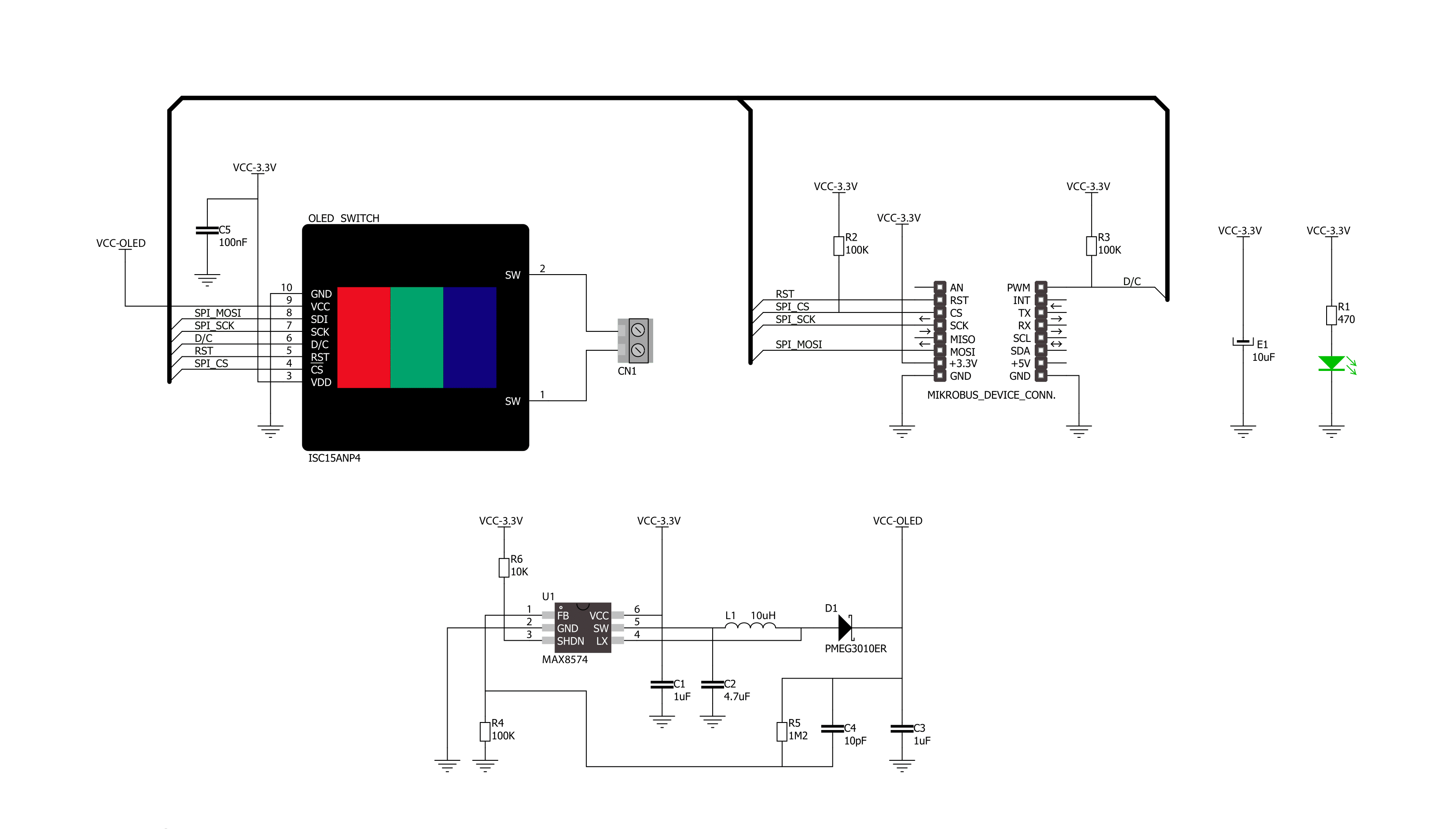
OLED Switch Click is based on the ISC15ANP4, a programmable smart display from NKK Switches. The OLED display has a 64x48 pixels resolution with up to 65K colors (16-bit depth), or 256 colors in 8-bit mode, and a 180° viewing angle. The life expectancy is up to 60000 hours depending on the luminance of the display and the percentage of the pixels set to on. The display is perfect for displaying simple information, whether as icons or words. The most interesting feature is that the display can be programmed to change the picture when needed. For example, you can design a reprogrammable keypad that switches from Latin to Cyrillic script or Chinese characters. The internal frame buffer on the OLED display holds 96x64 pixels with 2 bytes of 565 formatted color information for each. When displaying an image that is the size of the display (64x48), the image
will be displayed well unless scrolled. To scroll an image without having random pixels from unused space in the internal frame buffer, load a 96x64 image onto the OLED Switch Click with your desired image centered like the blue-colored area or similar. VisualTFT can be used to prepare the BMP images. There is a learn.microe.com article that explains how to take 16 or 24-bit BMP pictures and create C arrays. The article is about RGB matrices, but the same principle applies. The mechanical button itself is nicely built, with translucent black housing. When pressed, it gives satisfying tactile feedback and has a distinct, long travel of 4.5mm. Its contacts have a 0.1A@12VDC rating to switch an external circuit over screw terminals. The internal button circuit is an SPST and is normally open. The pressure on the button itself above 100N can damage the OLED. In
addition, this Click board™ features the MAX8574, a high-efficiency LCD boost with true shutdown from Analog Devices, that serves as a main OLED drive circuit power supply obtained from the mikroBUS™ 3.3V power rail. The OLED Switch Click uses an SPI serial interface to communicate with the host MCU. In addition, the OLED can be reset over the RST pin, and a CD pin can set data to be interpreted as a Command or as Data depending on the logic state. The host MCU cannot know the push button’s state over the mikroBUS™ socket. This Click board™ can be operated only with a 3.3V logic voltage level. The board must perform appropriate logic voltage level conversion before using MCUs with different logic levels. Also, it comes equipped with a library containing functions and an example code that can be used as a reference for further development.


Features overview
Development board
EasyPIC v8 for PIC24/dsPIC33 is a development board specially designed for the needs of rapid development of embedded applications. It supports a wide range of 16-bit PIC24/dsPIC33 microcontrollers from Microchip and has a broad set of unique functions, such as the first-ever embedded debugger/programmer. The development board is well organized and designed so that the end-user has all the necessary elements, such as switches, buttons, indicators, connectors, and others, in one place. Thanks to innovative manufacturing technology, EasyPIC v8 for PIC24/dsPIC33 provides a fluid and immersive working experience, allowing access anywhere and under any circumstances. Each part of the EasyPIC
v8 for PIC24/dsPIC33 development board contains the components necessary for the most efficient operation of the same board. In addition to the advanced integrated CODEGRIP programmer/debugger module, which offers many valuable programming/debugging options and seamless integration with the Mikroe software environment, the board also includes a clean and regulated power supply module for the development board. It can use a wide range of external power sources, including a battery, an external 12V power supply, and a power source via the USB Type-C (USB-C) connector. Communication options such as USB HOST/DEVICE, USB-UART, CAN, and LIN are also
included, including the well-established mikroBUS™ standard, two display options (graphical and character-based LCD), and several different DIP sockets. These sockets cover a wide range of 16-bit PIC24/dsPIC33 MCUs, from the smallest PIC24/dsPIC33 MCUs with only 14 up to 28 pins. EasyPIC v8 for PIC24/dsPIC33 is an integral part of the Mikroe ecosystem for rapid development. Natively supported by Mikroe software tools, it covers many aspects of prototyping and development thanks to a considerable number of different Click boards™ (over a thousand boards), the number of which is growing every day.

Microcontroller Overview
MCU Card / MCU
Architecture
dsPIC
MCU Memory (KB)
16
Silicon Vendor
Microchip
Pin count
28
RAM (Bytes)
2048
Used MCU Pins
mikroBUS™ mapper
Take a closer look
Click board™ Schematic
Step by step
Project assembly

Start by selecting your development board and Click board™. Begin with the EasyPIC v8 for PIC24/dsPIC33 as your development board.


Software Support
Library Description
This library contains API for Oled Switch Click driver.
Key functions:
oledswitch_reg_write- This function writes to control and configuration registers on the chipoledswitch_digital_write_pwm- This function sets the digital output signal for the PWM pinoledswitch_digital_write_rst- This function sets the digital output signal for the RST pin
Open Source
Code example
The complete application code and a ready-to-use project are available through the NECTO Studio Package Manager for direct installation in the NECTO Studio. The application code can also be found on the MIKROE GitHub account.
/*!
 * \file
 * \brief OledSwitch Click example
 *
 * # Description
 * This example showcases how to configure and use the OLED Switch Click. This Click is a
 * combination of a button and a full color organic LED display. Displays settings are first
 * loaded onto the chip and after that you can show any 64x48 pixel image on the display.
 *
 * The demo application is composed of two sections :
 *
 * ## Application Init
 * This function initializes and configures the Click modules. In order for the
 * Click to work properly, you need to configure display and power settings.
 * The full initialization of the chip is done in the default_cfg(...) function.
 *
 * ## Application Task
 * This function shows the user how to display images on the OLED screen. Every image you'd
 * like to display needs to have a resolution of 64x48 and be stored in a 6144 cell array.
 *
 * @note
 * Every pixel on the OLED screen is displayed at the time of writing to the chip (PWM 1).
 * Displaying speed can be directly controled by adding delays in the for loop section of
 * the draw_image(...) function.
 *
 * \author MikroE Team
 *
 */
// ------------------------------------------------------------------- INCLUDES

#include "board.h"
#include "log.h"
#include "oledswitch.h"
#include "oledswitch_image.h"

// ------------------------------------------------------------------ VARIABLES

static oledswitch_t oledswitch;

// ------------------------------------------------------ APPLICATION FUNCTIONS

void application_init ( )
{
    oledswitch_cfg_t cfg;

    //  Click initialization.

    oledswitch_cfg_setup( &cfg );
    OLEDSWITCH_MAP_MIKROBUS( cfg, MIKROBUS_1 );
    oledswitch_init( &oledswitch, &cfg );
    oledswitch_default_cfg( &oledswitch, OLEDSWITCH_BUFFER_SIZE_SMALL );
}

void application_task ( )
{
    oledswitch_draw_image( &oledswitch, array_red, OLEDSWITCH_IMG_SIZE_NORMAL );
    Delay_1sec( );

    oledswitch_draw_image( &oledswitch, array_green, OLEDSWITCH_IMG_SIZE_NORMAL );
    Delay_1sec( );

    oledswitch_draw_image( &oledswitch, array_blue, OLEDSWITCH_IMG_SIZE_NORMAL );
    Delay_1sec( );
}

int main ( void )
{
    /* Do not remove this line or clock might not be set correctly. */
    #ifdef PREINIT_SUPPORTED
    preinit();
    #endif

    application_init( );

    for ( ; ; )
    {
        application_task( );
    }

    return 0;
}

// ------------------------------------------------------------------------ END
Additional Support
Resources
Category:OLED