Attain accurate and real-time absolute angular positioning with MA302 and STM32F412ZG
From 0 to 60.000 RPM: Accurate angle measurement simplified

Published Feb 26, 2024
Click board™
Angle 5 Click
Dev. board
Nucleo-144 with STM32F412ZG MCU
Compiler
NECTO Studio
MCU
STM32F412ZG
Detect the absolute rotor position of brushless motors with ease, allowing for seamless control and optimization of motor performance
A
A
Hardware Overview
How does it work?
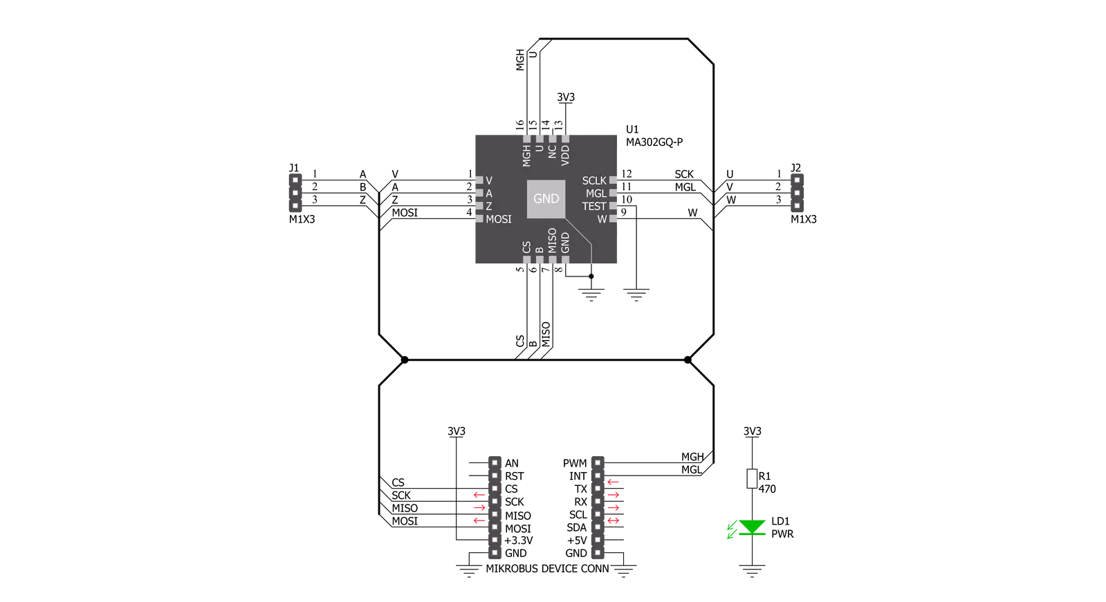
Angle 5 Click is based on the MA302, a 12-bit digital contactless angle sensor with ABZ and UVW incremental outputs from Monolithic Power Systems. This Click board™ can detect the absolute rotor position of a Brushless motor in real-time, even without a target magnet, by measuring the fringe field of the rotor. The sensor must be positioned at the correct place (in this case, below the rotor) to get the maximum value of the rotor magnetic field without being disturbed by other fields. The rotor magnetic field is then measured, and an adequate position was determined from that information. It uses the SPI serial interface for digital angle readout and configuration alongside a programmable magnetic field strength detection function for diagnostic checks. The magnetic field is detected with integrated Hall devices located in the center of the package. The angle is measured using the Spinaxis™ method, based on phase detection,
and generates a sinusoidal signal with a phase that represents the angle of the magnetic field. The angle is then obtained by a time-to-digital converter, which measures the time between the zero-crossing of the sinusoidal signal and the edge of a constant waveform. The time-to-digital represents an output from the front end to the digital conditioning block. This output delivers a digital number proportional to the angle of the magnetic field at the rate of 1MHz in a straightforward and open-loop manner. The Angle 5 Click communicates with MCU using the standard SPI serial interface for angle reading and register programming, which supports SPI Mode 0 and 3 and operates at clock rates up to 25 MHz. It also has the magnetic flags used for indication when the magnetic field at the sensor position is out of range, defined by the lower and upper magnetic field thresholds, routed on the PWM and INT pin of the mikroBUS™ socket labeled as MGH
and MGL. This Click board™ possesses an incremental encoder and block commutation function that uses three output pins each: ABZ and UVW. The ABZ output emulates a 10-bit incremental encoder (such as an optical encoder) providing logic pulses in quadrature, while the UVW output emulates the three Hall switches usually used for the block commutation of a three-phase electric motor. The ABZ and UVW pins of the MA302 are routed on two standard 2.54 mm (0.1 inches) pitch 1x3 header mounted on the Angle 5 Click so an external application can easily access it. This Click board™ can be operated only with a 3.3V logic voltage level. The board must perform appropriate logic voltage level conversion before using MCUs with different logic levels. Also, it comes equipped with a library containing functions and an example code that can be used as a reference for further development.


Features overview
Development board
Nucleo-144 with STM32F412ZG MCU board offers an accessible and adaptable avenue for users to explore new ideas and construct prototypes. It allows users to tailor their experience by selecting from a range of performance and power consumption features offered by the STM32 microcontroller. With compatible boards, the
internal or external SMPS dramatically decreases power usage in Run mode. Including the ST Zio connector, expanding ARDUINO Uno V3 connectivity, and ST morpho headers facilitate easy expansion of the Nucleo open development platform. The integrated ST-LINK debugger/programmer enhances convenience by
eliminating the need for a separate probe. Moreover, the board is accompanied by comprehensive free software libraries and examples within the STM32Cube MCU Package, further enhancing its utility and value.

Microcontroller Overview
MCU Card / MCU
Architecture
ARM Cortex-M4
MCU Memory (KB)
1024
Silicon Vendor
STMicroelectronics
Pin count
144
RAM (Bytes)
262144
You complete me!
Accessories
Click Shield for Nucleo-144 comes equipped with four mikroBUS™ sockets, with one in the form of a Shuttle connector, allowing all the Click board™ devices to be interfaced with the STM32 Nucleo-144 board with no effort. This way, MIKROE allows its users to add any functionality from our ever-growing range of Click boards™, such as WiFi, GSM, GPS, Bluetooth, ZigBee, environmental sensors, LEDs, speech recognition, motor control, movement sensors, and many more. Featuring an ARM Cortex-M microcontroller, 144 pins, and Arduino™ compatibility, the STM32 Nucleo-144 board offers limitless possibilities for prototyping and creating diverse applications. These boards are controlled and powered conveniently through a USB connection to program and efficiently debug the Nucleo-144 board out of the box, with an additional USB cable connected to the USB mini port on the board. Simplify your project development with the integrated ST-Link debugger and unleash creativity using the extensive I/O options and expansion capabilities. This Click Shield also has several switches that perform functions such as selecting the logic levels of analog signals on mikroBUS™ sockets and selecting logic voltage levels of the mikroBUS™ sockets themselves. Besides, the user is offered the possibility of using any Click board™ with the help of existing bidirectional level-shifting voltage translators, regardless of whether the Click board™ operates at a 3.3V or 5V logic voltage level. Once you connect the STM32 Nucleo-144 board with our Click Shield for Nucleo-144, you can access hundreds of Click boards™, working with 3.3V or 5V logic voltage levels.

2207V-2500kV BLDC Motor is an outrunner brushless DC motor with a kV rating of 2500 and an M5 shaft diameter. It is an excellent solution for fulfilling many functions initially performed by brushed DC motors or in RC drones, racing cars, and much more.

Used MCU Pins
mikroBUS™ mapper
Take a closer look
Click board™ Schematic
Step by step
Project assembly
Start by selecting your development board and Click board™. Begin with the Nucleo-144 with STM32F412ZG MCU as your development board.


Track your results in real time
Application Output
1. Application Output - In Debug mode, the 'Application Output' window enables real-time data monitoring, offering direct insight into execution results. Ensure proper data display by configuring the environment correctly using the provided tutorial.

2. UART Terminal - Use the UART Terminal to monitor data transmission via a USB to UART converter, allowing direct communication between the Click board™ and your development system. Configure the baud rate and other serial settings according to your project's requirements to ensure proper functionality. For step-by-step setup instructions, refer to the provided tutorial.

3. Plot Output - The Plot feature offers a powerful way to visualize real-time sensor data, enabling trend analysis, debugging, and comparison of multiple data points. To set it up correctly, follow the provided tutorial, which includes a step-by-step example of using the Plot feature to display Click board™ readings. To use the Plot feature in your code, use the function: plot(*insert_graph_name*, variable_name);. This is a general format, and it is up to the user to replace 'insert_graph_name' with the actual graph name and 'variable_name' with the parameter to be displayed.

Software Support
Library Description
This library contains API for Angle 5 Click driver.
Key functions:
angle5_read_raw_angle- Use this function to read raw angle dataangle5_read_angle_deg- Use this function to read angle data
Open Source
Code example
The complete application code and a ready-to-use project are available through the NECTO Studio Package Manager for direct installation in the NECTO Studio. The application code can also be found on the MIKROE GitHub account.
/*!
 * \file
 * \brief Angle5 Click example
 *
 * # Description
 * Angle 5 Click is a magnetic rotational sensor.
 * It communicates with the target microcontroller over SPI interface.
 *
 * The demo application is composed of two sections :
 *
 * ## Application Init
 * Initializes the driver.
 *
 * ## Application Task
 * Reads the angle position of the magnet and displays the results on the USB UART.
 *
 * \author MikroE Team
 *
 */
// ------------------------------------------------------------------- INCLUDES

#include "board.h"
#include "log.h"
#include "angle5.h"

// ------------------------------------------------------------------ VARIABLES

static angle5_t angle5;
static log_t logger;

// ------------------------------------------------------ APPLICATION FUNCTIONS

void application_init ( void )
{
    log_cfg_t log_cfg;
    angle5_cfg_t cfg;

    /**
     * Logger initialization.
     * Default baud rate: 115200
     * Default log level: LOG_LEVEL_DEBUG
     * @note If USB_UART_RX and USB_UART_TX
     * are defined as HAL_PIN_NC, you will
     * need to define them manually for log to work.
     * See @b LOG_MAP_USB_UART macro definition for detailed explanation.
     */
    LOG_MAP_USB_UART( log_cfg );
    log_init( &logger, &log_cfg );
    log_info( &logger, "---- Application Init ----" );

    //  Click initialization.

    angle5_cfg_setup( &cfg );
    ANGLE5_MAP_MIKROBUS( cfg, MIKROBUS_1 );
    angle5_init( &angle5, &cfg );
}

void application_task ( void )
{
    float new_angle = 0;

    new_angle = angle5_read_angle_deg( &angle5 );
    log_printf( &logger, "Angle: %.2f\r\n", new_angle );

    Delay_ms ( 100 );
}

int main ( void )
{
    /* Do not remove this line or clock might not be set correctly. */
    #ifdef PREINIT_SUPPORTED
    preinit();
    #endif

    application_init( );

    for ( ; ; )
    {
        application_task( );
    }

    return 0;
}


// ------------------------------------------------------------------------ END
Additional Support
Resources
Category:Magnetic


