Steer brushless motor with precision using TMC6300 and STM32F413ZH
Power driver for BLDC/PMSM motors

Published Feb 14, 2024
Click board™
Brushless 27 Click
Dev. board
Nucleo 144 with STM32F413ZH MCU
Compiler
NECTO Studio
MCU
STM32F413ZH
Optimize the performance of a BLDC motor with precise control over the flow of electrical power
A
A
Hardware Overview
How does it work?
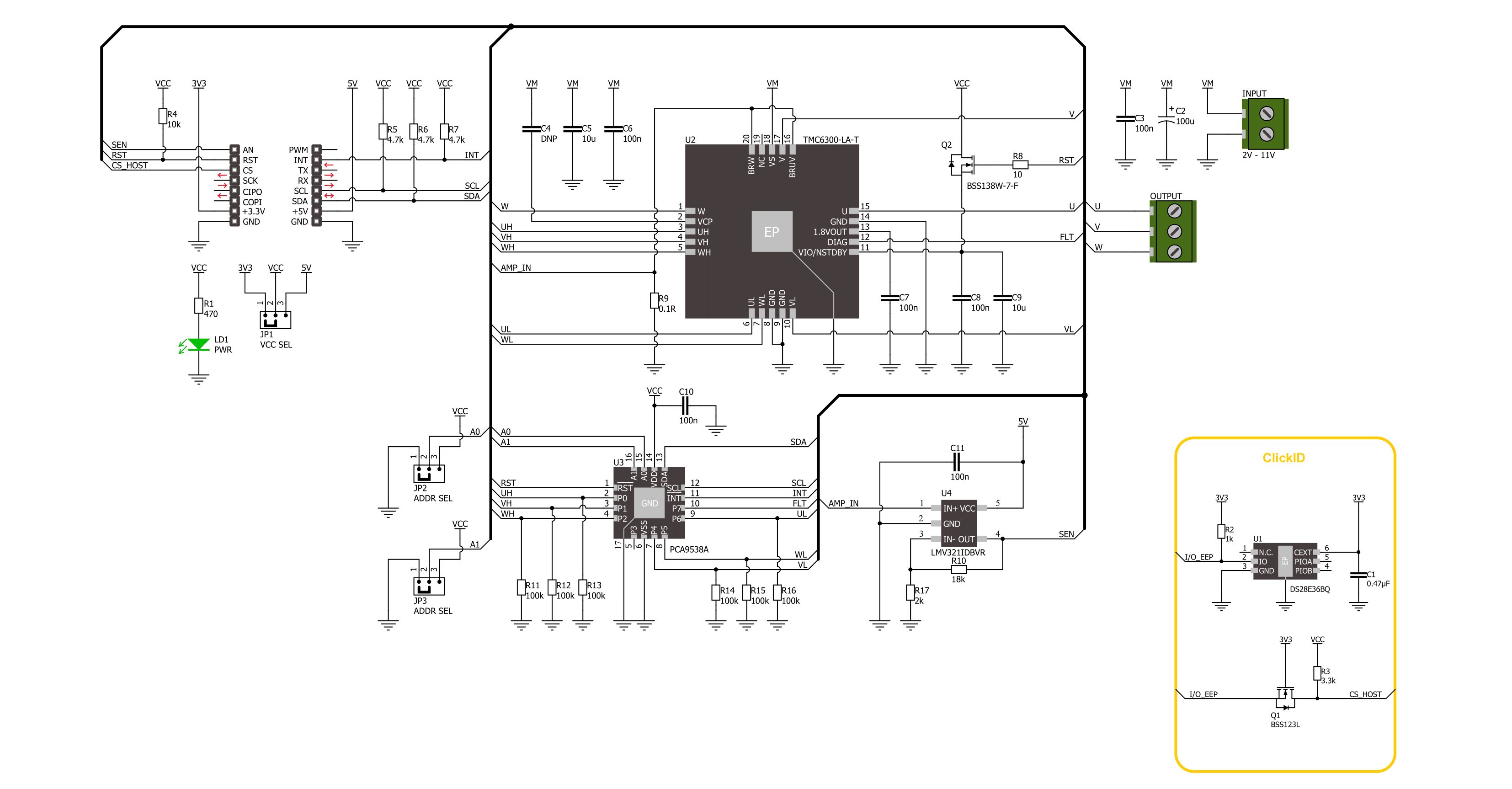
Brushless 27 Click is based on the TMC6300, a power driver for BLDC/PMSM motors from Analog Devices. It integrates a charge pump and ultra-low standby current, ensuring the best efficiency and longest battery life. The 3-phase driver offers three half-bridges with individual enable signals for low-side and high-side. It is optimized for BLDC motor control, as well as control of other magnetic actuators. Each MOSFET of each half-bridge can be individually switched on and off. Internal break-before-make (BBM) logic ensures that no cross-conduction occurs. The driver operates a BLDC motor with a block or sine-commutation using 6-line control from the PCA9538, a low-voltage
8-bit I/O port from NXP. The foot-points of the motor driver are connected via a sense resistor to the LMV321, a low-voltage rail-to-rail output operational amplifier from Texas Instruments. This OP-AMP allows current measurement of the motor to control or limit motor torque. You can change this sense resistor (R9) to set other maximum motor current values according to the table at the bottom of the Brushless 27 Click. The external power supply in a range of 2 – 11V can be connected over the INPUT screw terminal. Brushless 27 Click uses a standard 2-wire I2C interface of the PCA9538 to communicate with the host MCU, supporting clock frequency of up to
400kHz. The I2C address can be selected over the ADDR SEL jumpers. The I/O prot can be reset over the RST pin, while the host MCU can measure the current over the SEN pin. The diagnostic output signals any overcurrent or overtemperature condition over the INT pin. This Click board™ can operate with either 3.3V or 5V logic voltage levels selected via the VCC SEL jumper. This way, both 3.3V and 5V capable MCUs can use the communication lines properly. Also, this Click board™ comes equipped with a library containing easy-to-use functions and an example code that can be used for further development.

Features overview
Development board
Nucleo-144 with STM32F413ZH MCU board offers an accessible and adaptable avenue for users to explore new ideas and construct prototypes. It allows users to tailor their experience by selecting from a range of performance and power consumption features offered by the STM32 microcontroller. With compatible boards, the
internal or external SMPS dramatically decreases power usage in Run mode. Including the ST Zio connector, expanding ARDUINO Uno V3 connectivity, and ST morpho headers facilitate easy expansion of the Nucleo open development platform. The integrated ST-LINK debugger/programmer enhances convenience by
eliminating the need for a separate probe. Moreover, the board is accompanied by comprehensive free software libraries and examples within the STM32Cube MCU Package, further enhancing its utility and value.

Microcontroller Overview
MCU Card / MCU

Architecture
ARM Cortex-M4
MCU Memory (KB)
1536
Silicon Vendor
STMicroelectronics
Pin count
144
RAM (Bytes)
327680
You complete me!
Accessories
Click Shield for Nucleo-144 comes equipped with four mikroBUS™ sockets, with one in the form of a Shuttle connector, allowing all the Click board™ devices to be interfaced with the STM32 Nucleo-144 board with no effort. This way, MIKROE allows its users to add any functionality from our ever-growing range of Click boards™, such as WiFi, GSM, GPS, Bluetooth, ZigBee, environmental sensors, LEDs, speech recognition, motor control, movement sensors, and many more. Featuring an ARM Cortex-M microcontroller, 144 pins, and Arduino™ compatibility, the STM32 Nucleo-144 board offers limitless possibilities for prototyping and creating diverse applications. These boards are controlled and powered conveniently through a USB connection to program and efficiently debug the Nucleo-144 board out of the box, with an additional USB cable connected to the USB mini port on the board. Simplify your project development with the integrated ST-Link debugger and unleash creativity using the extensive I/O options and expansion capabilities. This Click Shield also has several switches that perform functions such as selecting the logic levels of analog signals on mikroBUS™ sockets and selecting logic voltage levels of the mikroBUS™ sockets themselves. Besides, the user is offered the possibility of using any Click board™ with the help of existing bidirectional level-shifting voltage translators, regardless of whether the Click board™ operates at a 3.3V or 5V logic voltage level. Once you connect the STM32 Nucleo-144 board with our Click Shield for Nucleo-144, you can access hundreds of Click boards™, working with 3.3V or 5V logic voltage levels.

Brushless DC (BLDC) Motor with a Hall sensor represents a high-performance motor from the 42BLF motor series. This motor, wired in a star configuration, boasts a Hall Effect angle of 120°, ensuring precise and reliable performance. With a compact motor length of 47mm and a lightweight design tipping the scales at just 0.29kg, this BLDC motor is engineered to meet your needs. Operating flawlessly at a voltage rating of 24VDC and a speed range of 4000 ± 10% RPM, this motor offers consistent and dependable power. It excels in a normal operational temperature range from -20 to +50°C, maintaining efficiency with a rated current of 1.9A. Also, this product seamlessly integrates with all Brushless Click boards™ and those that require BLDC motors with Hall sensors.

Used MCU Pins
mikroBUS™ mapper
Take a closer look
Click board™ Schematic
Step by step
Project assembly
Start by selecting your development board and Click board™. Begin with the Nucleo 144 with STM32F413ZH MCU as your development board.


Software Support
Library Description
This library contains API for Brushless 27 Click driver.
Key functions:
brushless27_set_pins- Brushless 27 set pins function.brushless27_set_trap_com_state- Brushless 27 set trapezoidal com state function.brushless27_drive_motor- Brushless 27 drive motor function.
Open Source
Code example
The complete application code and a ready-to-use project are available through the NECTO Studio Package Manager for direct installation in the NECTO Studio. The application code can also be found on the MIKROE GitHub account.
/*!
 * @file main.c
 * @brief Brushless 27 Click example
 *
 * # Description
 * This example demonstrates the use of the Brushless 27 Click board by driving the
 * motor in both directions at different speeds.
 *
 * The demo application is composed of two sections :
 *
 * ## Application Init
 * Initializes the driver and performs the Click default configuration.
 *
 * ## Application Task
 * Drives the motor in both directions and changes the motor speed approximately every 2 seconds.
 * The driving direction and speed will be displayed on the USB UART.
 *
 * @author Stefan Ilic
 *
 */

#include "board.h"
#include "log.h"
#include "brushless27.h"

static brushless27_t brushless27;
static log_t logger;

void application_init ( void )
{
    log_cfg_t log_cfg;  /**< Logger config object. */
    brushless27_cfg_t brushless27_cfg;  /**< Click config object. */

    /**
     * Logger initialization.
     * Default baud rate: 115200
     * Default log level: LOG_LEVEL_DEBUG
     * @note If USB_UART_RX and USB_UART_TX
     * are defined as HAL_PIN_NC, you will
     * need to define them manually for log to work.
     * See @b LOG_MAP_USB_UART macro definition for detailed explanation.
     */
    LOG_MAP_USB_UART( log_cfg );
    log_init( &logger, &log_cfg );
    log_info( &logger, " Application Init " );

    // Click initialization.
    brushless27_cfg_setup( &brushless27_cfg );
    BRUSHLESS27_MAP_MIKROBUS( brushless27_cfg, MIKROBUS_1 );
    if ( I2C_MASTER_ERROR == brushless27_init( &brushless27, &brushless27_cfg ) )
    {
        log_error( &logger, " Communication init." );
        for ( ; ; );
    }

    if ( BRUSHLESS27_ERROR == brushless27_default_cfg ( &brushless27 ) )
    {
        log_error( &logger, " Default configuration." );
        for ( ; ; );
    }

    log_info( &logger, " Application Task " );
}

void application_task ( void )
{
    log_printf ( &logger, "\r\n Driving motor clockwise \r\n" );
    for ( uint8_t speed = BRUSHLESS27_SPEED_MIN; speed <= BRUSHLESS27_SPEED_MAX; speed += 20 )
    {
        log_printf ( &logger, " Speed gain: %u\r\n", ( uint16_t ) speed );
        if ( BRUSHLESS27_OK != brushless27_drive_motor ( &brushless27, BRUSHLESS27_DIR_CW, speed, 2000 ) )
        {
            log_error ( &logger, " Drive motor " );
        }
    }
    Delay_ms ( 1000 );

    log_printf ( &logger, "\r\n Driving motor counter-clockwise \r\n" );
    for ( uint8_t speed = BRUSHLESS27_SPEED_MIN; speed <= BRUSHLESS27_SPEED_MAX; speed += 20 )
    {
        log_printf ( &logger, " Speed gain: %u\r\n", ( uint16_t ) speed );
        if ( BRUSHLESS27_OK != brushless27_drive_motor ( &brushless27, BRUSHLESS27_DIR_CCW, speed, 2000 ) )
        {
            log_error ( &logger, " Drive motor " );
        }
    }
    Delay_ms ( 1000 );
}

int main ( void )
{
    /* Do not remove this line or clock might not be set correctly. */
    #ifdef PREINIT_SUPPORTED
    preinit();
    #endif

    application_init( );

    for ( ; ; )
    {
        application_task( );
    }

    return 0;
}

// ------------------------------------------------------------------------ END
Additional Support
Resources
Category:Brushless


