Start your path to wellness here with KX126-1063 and STM32F413ZH
Step up to a healthier you with our pedometer!
Published Feb 14, 2024
Click board™
Pedometer 3 Click
Dev. board
Nucleo 144 with STM32F413ZH MCU
Compiler
NECTO Studio
MCU
STM32F413ZH
Our smart pedometer provides accurate step counting, distance measurement, and calorie estimation, helping you make informed choices for a more active life
A
A
Hardware Overview
How does it work?
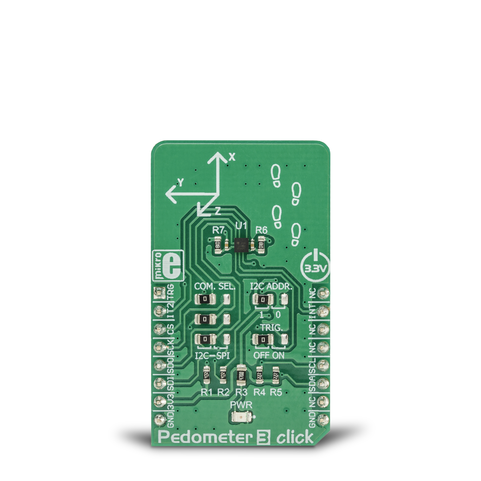
Pedometer 3 Click is based on the KX126-1063, ±2g / ±4g / ±8g / ±16g tri-axis digital accelerometer from Rohm Semiconductor. This sensor utilizes an advanced acceleration sensing method, based on the differential capacitance. The integrated MEMS, produced with the proprietary Kionix technology, is composed of two plates. One is fixed to the substrate, while the other can move freely along a single axis. The acceleration causes the change in the capacitance between these plates, which is then processed by an integrated ASIC. The ASIC incorporates a capacitance-to-voltage amplifier which converts the differential capacitance of the MEMS sensor into an analog voltage, used as the input for the low-noise A/D converter (ADC). The integrated ASIC also contains the logic section used to set all the operational parameters of the KX126-1063, such as the data rate, filter settings, interrupts, ADC resolution, and other settings. The ASIC also incorporates an OTP memory that contains the calibration parameters and other device-specific settings used on each power-on reset (POR) cycle. The ADC can be operated with the resolution of 8 or 16 bits. This allows power consumption to be managed, as the lower resolution typically allows less power consumption. The power consumption is also affected by the output data rate value (ODR). The ODR value can be set for each mode and is set by different bits located in the respective configuration registers. As previously mentioned, the KX126-1063 IC features a range of different detection algorithms, which are used to detect a range of movement and acceleration events. The pedometer functionality is one of these features. In the datasheet, a term engine is used. The pedometer engine can be disabled or enabled, it can have the signal filtering conditioning applied to it (so that the acceleration offset is removed, and the peak detection is improved), it can use a
specific acceleration range from ±2g to ±16g, it can set its output data rate register to a specific value, it can have the step count overflow reported as the interrupt on one of the physical pins (INT1, and INT2 pins of the IC, routed to the mikroBUS™ INT and RST pins, respectively), step increment event can also be directed to trigger an interrupt on one of the INT pins. The step detection parameters of the pedometer engine itself can be configured by the user. There are ten pedometer control registers (PED_CNTL1 to PED_CNTL10) that cover various aspects of the pedometer engine, in addition to general configuration registers which are common to all engines of the KX126-1063 IC. These registers affect the step detection sensitivity, the number of steps discarded before the actual counting begins, the scaling factor, etc. The datasheet of the KX126-1063 IC offers a detailed explanation of each register and its function. However, the Click board™ comes with the mikroSDK compatible library which contains simplified functions, that allow simple setup of the KX126-1063 sensor IC and rapid application development. The advanced interrupt engine allows both the interrupt pins INT1 and INT2 to be configured by the user. They can be used to trigger an interrupt on the host MCU, using a wide range of sources, including sample buffer events, various engine-specific events, general purpose interrupts (such as wake-up, data ready, and similar), etc. Having two independent interrupt pins is a great solution for optimizing the firmware of the host controller, as the register polling can be reduced greatly, saving valuable MCU processing resources. Another feature of the KX126-1063 IC is its advanced sample buffer, which can store up to 2048 bytes of data. It can be operated in four different modes, including FIFO, FILO, Stream, and Trigger modes. Each mode applies a different set of rules when filling in the sample buffer, and
when the watermark level is reached (a user-configurable threshold). The TRIG pin used for an external buffer control is routed to the mikroBUS™ AN pin labeled as TRG. This pin is used when the sample buffer is operated in Trigger mode: a high logic state on this pin will retain all the samples in the buffer up to the current position (not discarding them anymore when the threshold level is reached), continuing to fill the buffer until its full. When this option is not used, the TRIG pin should be grounded, which is done by positioning the SMD jumper labeled as TRIG, to OFF position (the factory default for the Click board™). Again, more detailed information about the advanced sample buffer can be found in the KX126-1063 datasheet. Each KX126-1063 is factory calibrated, and its calibration parameters are stored in the one-time programmable memory (OTP). These parameters include the gain corrections and offset calibration. After each POR cycle, these calibration values are automatically applied, reducing the output error. Along with the used MEMS differential sensing technology, this reduces the measurement error to a virtually unmeasurable value. A built-in self-test function allows reliable operation of the Pedometer 3 click. Pedometer 3 click can use both SPI and I2C interfaces. A group of SMD jumpers labeled as COM SEL is used to select either of the communication interfaces. Please note that all the COM SEL jumpers must be positioned at the same setting, else the communication with the Click board™ will not be possible. When operated in I2C mode, the slave address of the device can be changed by switching the position of the SMD jumper labeled as I2C ADD. The Click board™ should be interfaced only with MCUs that use the communication voltage level of 3.3V.

Features overview
Development board
Nucleo-144 with STM32F413ZH MCU board offers an accessible and adaptable avenue for users to explore new ideas and construct prototypes. It allows users to tailor their experience by selecting from a range of performance and power consumption features offered by the STM32 microcontroller. With compatible boards, the
internal or external SMPS dramatically decreases power usage in Run mode. Including the ST Zio connector, expanding ARDUINO Uno V3 connectivity, and ST morpho headers facilitate easy expansion of the Nucleo open development platform. The integrated ST-LINK debugger/programmer enhances convenience by
eliminating the need for a separate probe. Moreover, the board is accompanied by comprehensive free software libraries and examples within the STM32Cube MCU Package, further enhancing its utility and value.

Microcontroller Overview
MCU Card / MCU

Architecture
ARM Cortex-M4
MCU Memory (KB)
1536
Silicon Vendor
STMicroelectronics
Pin count
144
RAM (Bytes)
327680
You complete me!
Accessories
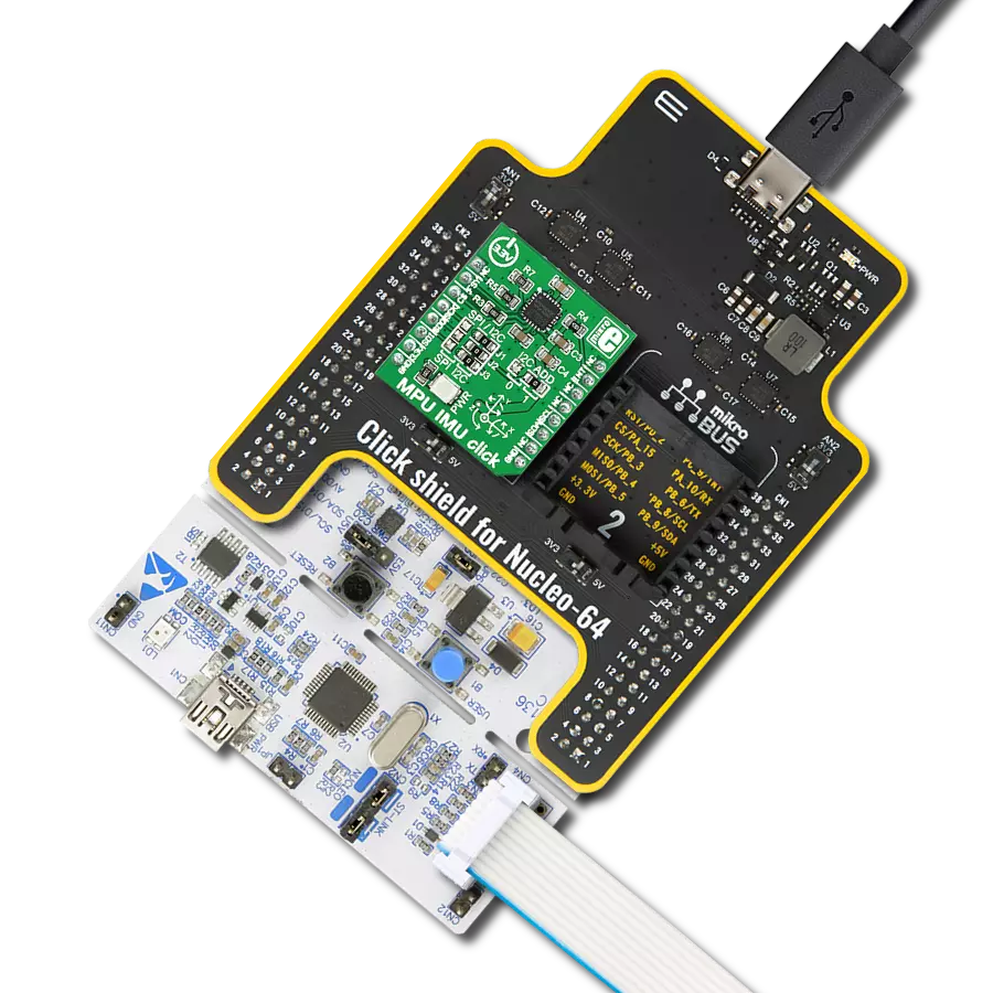
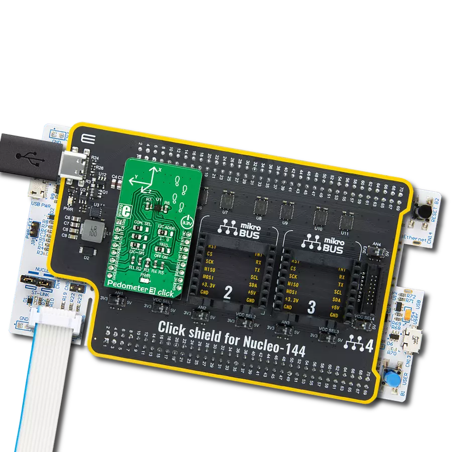
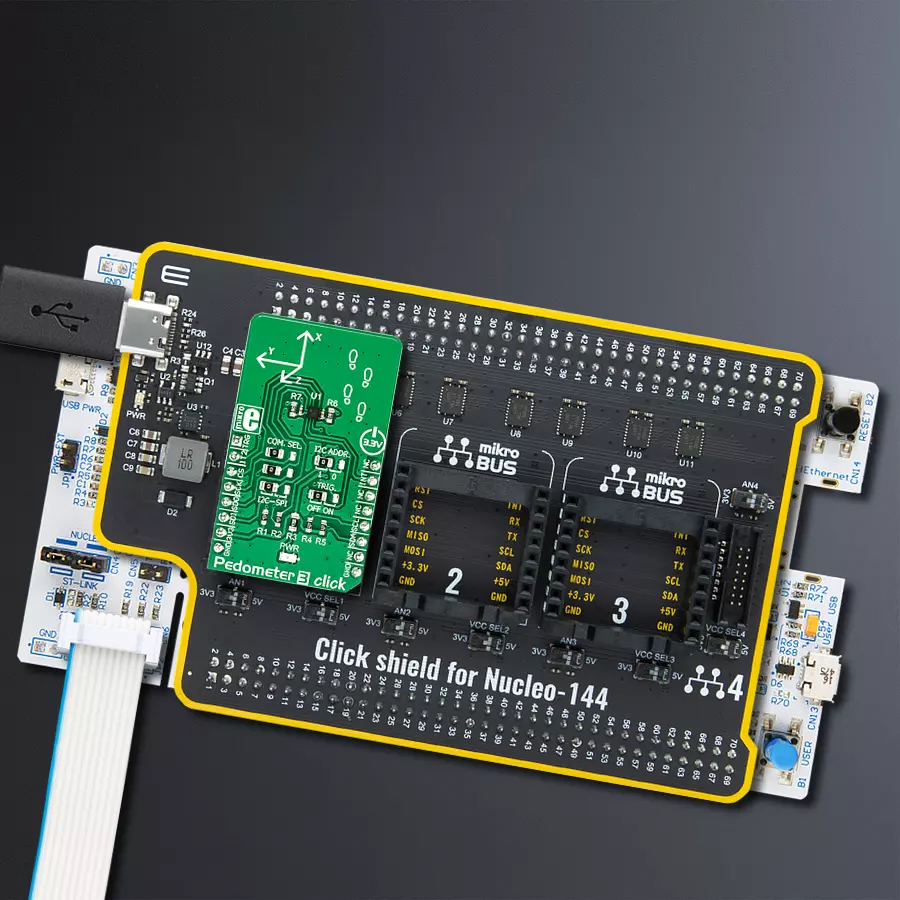
Click Shield for Nucleo-144 comes equipped with four mikroBUS™ sockets, with one in the form of a Shuttle connector, allowing all the Click board™ devices to be interfaced with the STM32 Nucleo-144 board with no effort. This way, MIKROE allows its users to add any functionality from our ever-growing range of Click boards™, such as WiFi, GSM, GPS, Bluetooth, ZigBee, environmental sensors, LEDs, speech recognition, motor control, movement sensors, and many more. Featuring an ARM Cortex-M microcontroller, 144 pins, and Arduino™ compatibility, the STM32 Nucleo-144 board offers limitless possibilities for prototyping and creating diverse applications. These boards are controlled and powered conveniently through a USB connection to program and efficiently debug the Nucleo-144 board out of the box, with an additional USB cable connected to the USB mini port on the board. Simplify your project development with the integrated ST-Link debugger and unleash creativity using the extensive I/O options and expansion capabilities. This Click Shield also has several switches that perform functions such as selecting the logic levels of analog signals on mikroBUS™ sockets and selecting logic voltage levels of the mikroBUS™ sockets themselves. Besides, the user is offered the possibility of using any Click board™ with the help of existing bidirectional level-shifting voltage translators, regardless of whether the Click board™ operates at a 3.3V or 5V logic voltage level. Once you connect the STM32 Nucleo-144 board with our Click Shield for Nucleo-144, you can access hundreds of Click boards™, working with 3.3V or 5V logic voltage levels.

Used MCU Pins
mikroBUS™ mapper
Take a closer look
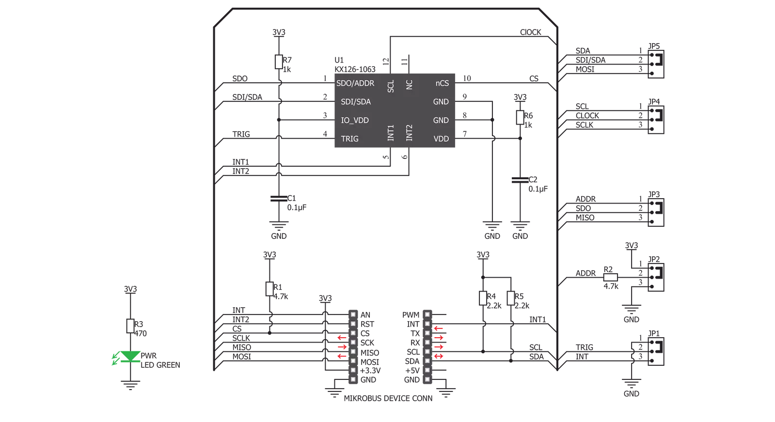
Click board™ Schematic
Step by step
Project assembly
Start by selecting your development board and Click board™. Begin with the Nucleo 144 with STM32F413ZH MCU as your development board.


Track your results in real time
Application Output
1. Application Output - In Debug mode, the 'Application Output' window enables real-time data monitoring, offering direct insight into execution results. Ensure proper data display by configuring the environment correctly using the provided tutorial.

2. UART Terminal - Use the UART Terminal to monitor data transmission via a USB to UART converter, allowing direct communication between the Click board™ and your development system. Configure the baud rate and other serial settings according to your project's requirements to ensure proper functionality. For step-by-step setup instructions, refer to the provided tutorial.

3. Plot Output - The Plot feature offers a powerful way to visualize real-time sensor data, enabling trend analysis, debugging, and comparison of multiple data points. To set it up correctly, follow the provided tutorial, which includes a step-by-step example of using the Plot feature to display Click board™ readings. To use the Plot feature in your code, use the function: plot(*insert_graph_name*, variable_name);. This is a general format, and it is up to the user to replace 'insert_graph_name' with the actual graph name and 'variable_name' with the parameter to be displayed.

Software Support
Library Description
This library contains API for Pedometer 3 Click driver.
Key functions:
pedometer3_get_hp_accel_axis- High Pass Accel axis datapedometer3_get_accel_axis- Accel axis datapedometer3_get_step_counter- Pedometer step counter
Open Source
Code example
The complete application code and a ready-to-use project are available through the NECTO Studio Package Manager for direct installation in the NECTO Studio. The application code can also be found on the MIKROE GitHub account.
/*!
 * \file
 * \brief Pedometer3 Click example
 *
 * # Description
 * The demo application displays measuring 2 accelerometers (normal accel and high pass accel),
 * counting steps and displaying tilt positions.
 * The sensor includes additional feature and setups that you can look up in the library.
 *
 * The demo application is composed of two sections :
 *
 * ## Application Init
 * Configuring Clicks and log objects.
 * Settings the Click in the default configuration.
 *
 * ## Application Task
 * Reads Accel and High Pass Accel X/Y/Z axis and detect Tilt Position.
 * All data logs on the USBUART every 400 ms.
 *
 * \author Katarina Perendic
 *
 */
// ------------------------------------------------------------------- INCLUDES

#include "board.h"
#include "log.h"
#include "pedometer3.h"

// ------------------------------------------------------------------ VARIABLES

static pedometer3_t pedometer3;
static log_t logger;

// ------------------------------------------------------ APPLICATION FUNCTIONS

void application_init ( void )
{
    log_cfg_t log_cfg;
    pedometer3_cfg_t cfg;
    uint8_t tmp;

    /**
     * Logger initialization.
     * Default baud rate: 115200
     * Default log level: LOG_LEVEL_DEBUG
     * @note If USB_UART_RX and USB_UART_TX
     * are defined as HAL_PIN_NC, you will
     * need to define them manually for log to work.
     * See @b LOG_MAP_USB_UART macro definition for detailed explanation.
     */
    LOG_MAP_USB_UART( log_cfg );
    log_init( &logger, &log_cfg );
    log_info( &logger, "---- Application Init ----" );

    //  Click initialization.
    pedometer3_cfg_setup( &cfg );
    PEDOMETER3_MAP_MIKROBUS( cfg, MIKROBUS_1 );
    pedometer3_init( &pedometer3, &cfg );

    // Default Click configurations
    pedometer3_default_cfg( &pedometer3 );

    tmp = PEDOMETER3_CNTL1_MODE_LOW_POWER | PEDOMETER3_CNTL1_MODE_LOW_POWER |
          PEDOMETER3_CNTL1_RES_MODE_LOWER_NOISE | PEDOMETER3_CNTL1_DATA_READY_DISABLE |
          PEDOMETER3_CNTL1_G_RANGE_2g | PEDOMETER3_CNTL1_TAP_ENABLE |
          PEDOMETER3_CNTL1_PEDOMETER_ENABLE | PEDOMETER3_CNTL1_TILT_ENABLE;

    pedometer3_generic_write( &pedometer3, PEDOMETER3_REG_CONTROL_1, &tmp, 1 );
}

void application_task ( void )
{
    static uint16_t ped_step = 0;
    pedometer3_axis_t accel_axis;
    pedometer3_axis_t highpass_axis;
    pedometer3_tilt_position_t tilt;

    pedometer3_get_accel_axis( &pedometer3, &accel_axis );
    pedometer3_get_hp_accel_axis( &pedometer3, &highpass_axis );
    ped_step += pedometer3_get_step_counter( &pedometer3 );

    log_printf( &logger, "___________ Pedometer 3 Click _____________\r\n");

    log_printf( &logger, "--  Accel : [ X ]: %d / [ Y ]: %d / [ Z ]: %d \r\n",
                accel_axis.x, accel_axis.y, accel_axis.z );
    log_printf( &logger, "--  HP Accel : [ X ]: %d / [ Y ]: %d / [ Z ]: %d \r\n",
                highpass_axis.x, highpass_axis.y, highpass_axis.z );

    log_printf( &logger, "--  Step counter : [ STEP ]: %d \r\n", ped_step );

    pedometer3_get_tilt_position( &pedometer3, &tilt);

    switch ( tilt.current_pos )
    {
        case PEDOMETER3_TILT_POSITION_LEFT:
        {
            log_printf( &logger, "--  Current Tilt Position: [ LEFT ] \r\n" );
            break;
        }
        case PEDOMETER3_TILT_POSITION_RIGHT:
        {
            log_printf( &logger, "--  Current Tilt Position: [ RIGHT ] \r\n" );
            break;
        }
        case PEDOMETER3_TILT_POSITION_DOWN:
        {
            log_printf( &logger, "--  Current Tilt Position: [ DOWN ] \r\n" );
            break;
        }
        case PEDOMETER3_TILT_POSITION_UP:
        {
            log_printf( &logger, "--  Current Tilt Position: [ UP ] \r\n" );
            break;
        }
        case PEDOMETER3_TILT_POSITION_FACE_DOWN:
        {
            log_printf( &logger, "--  Current Tilt Position: [ FACE DOWN ] \r\n" );
            break;
        }
        case PEDOMETER3_TILT_POSITION_FACE_UP:
        {
            log_printf( &logger, "--  Current Tilt Position: [ FACE UP ] \r\n" );
            break;
        }
    }

    Delay_ms ( 400 );
}

int main ( void )
{
    /* Do not remove this line or clock might not be set correctly. */
    #ifdef PREINIT_SUPPORTED
    preinit();
    #endif

    application_init( );

    for ( ; ; )
    {
        application_task( );
    }

    return 0;
}


// ------------------------------------------------------------------------ END