Experience the next level of charging efficiency with MCP73113 and STM32F030R8
Your devices deserve the best charging experience

Published Feb 26, 2024
Click board™
Charger 5 click
Dev. board
Nucleo-64 with STM32F030R8 MCU
Compiler
NECTO Studio
MCU
STM32F030R8
Say goodbye to low battery anxiety with our reliable charging solution
A
A
Hardware Overview
How does it work?
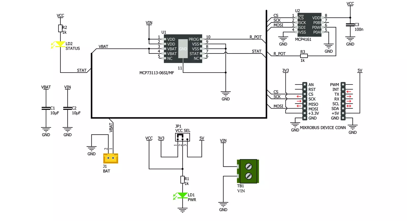
Charger 5 Click is based on the MCP73113, a single-cell Li-Po/Li-Ion battery charge from Microchip, along with the digital potentiometer chip labeled as MCP4161, from the same company. This click can easily and securely charge and fast-charge batteries on many devices that use 3.7V Li-Po/Li-Ion batteries. The constant charging current on the MCP73113 is set by a resistor connected between the PROG pin and the VCC; instead of using the conventional resistor, this board employs the MCP4161 digital potentiometer IC, which allows setting the constant charging current via the SPI interface. This way, the constant charging current can be set from 100mA to 950mA. The MCP73113 charger features several different battery charging protection and optimization schemes to keep the charging process safe and efficient. The undervoltage protection shuts the charger circuit down if the connected input voltage is below the threshold value.
The overvoltage protection will also put the device in shutdown mode if the input voltage exceeds the threshold value. Also, the connected input voltage should be 150mV greater than the battery voltage, or else it will remain in a power-down state. This prevents the battery from draining in case there's no input voltage. Therefore, the input voltage range should stay between 5V and 6.5V. The device is resistant to voltage spikes up to 18V on its input connector, but for proper operation, the input voltage should stay in the recommended voltage range. The connected battery voltage is constantly monitored. If it drops below the charging threshold and if all the other input voltage charging conditions are met, the charging process will start. When the battery is charged to the factory-set threshold, the charging will be stopped to prevent battery overcharging. The charging threshold for the MCP73113 charger IC used on this click is set to 4.2V.
If a Li-Ion battery is discharged below 3V, it must be pre-charged with around 10% of the full charge current. This means that the charging current, in this case, will be 10% of the fast charging current set by the MCP4161 digital potentiometer. Charger 5 click detects a short circuit on the battery connector. The short circuit is also reported in case of a faulty battery cell. If such an event occurs, the charger will enter the shutdown mode. The MCP73113 charger IC features thermal management too, which regulates the charging current, based on the die temperature. If the IC die is heated over 150°C, the device will be shut down. The onboard SMD jumper selector selects voltage for the digital potentiometer IC and SPI logic levels. There are also two onboard connectors. One connector is a screw terminal used to connect the external power supply (5V to 6.5V). The other connector is the Li-Po/Li-Ion battery 2.54mm header connector.

Features overview
Development board
Nucleo-64 with STM32F030R8 MCU offers a cost-effective and adaptable platform for developers to explore new ideas and prototype their designs. This board harnesses the versatility of the STM32 microcontroller, enabling users to select the optimal balance of performance and power consumption for their projects. It accommodates the STM32 microcontroller in the LQFP64 package and includes essential components such as a user LED, which doubles as an ARDUINO® signal, alongside user and reset push-buttons, and a 32.768kHz crystal oscillator for precise timing operations. Designed with expansion and flexibility in mind, the Nucleo-64 board features an ARDUINO® Uno V3 expansion connector and ST morpho extension pin
headers, granting complete access to the STM32's I/Os for comprehensive project integration. Power supply options are adaptable, supporting ST-LINK USB VBUS or external power sources, ensuring adaptability in various development environments. The board also has an on-board ST-LINK debugger/programmer with USB re-enumeration capability, simplifying the programming and debugging process. Moreover, the board is designed to simplify advanced development with its external SMPS for efficient Vcore logic supply, support for USB Device full speed or USB SNK/UFP full speed, and built-in cryptographic features, enhancing both the power efficiency and security of projects. Additional connectivity is
provided through dedicated connectors for external SMPS experimentation, a USB connector for the ST-LINK, and a MIPI® debug connector, expanding the possibilities for hardware interfacing and experimentation. Developers will find extensive support through comprehensive free software libraries and examples, courtesy of the STM32Cube MCU Package. This, combined with compatibility with a wide array of Integrated Development Environments (IDEs), including IAR Embedded Workbench®, MDK-ARM, and STM32CubeIDE, ensures a smooth and efficient development experience, allowing users to fully leverage the capabilities of the Nucleo-64 board in their projects.

Microcontroller Overview
MCU Card / MCU

Architecture
ARM Cortex-M0
MCU Memory (KB)
64
Silicon Vendor
STMicroelectronics
Pin count
64
RAM (Bytes)
8192
You complete me!
Accessories
Click Shield for Nucleo-64 comes equipped with two proprietary mikroBUS™ sockets, allowing all the Click board™ devices to be interfaced with the STM32 Nucleo-64 board with no effort. This way, Mikroe allows its users to add any functionality from our ever-growing range of Click boards™, such as WiFi, GSM, GPS, Bluetooth, ZigBee, environmental sensors, LEDs, speech recognition, motor control, movement sensors, and many more. More than 1537 Click boards™, which can be stacked and integrated, are at your disposal. The STM32 Nucleo-64 boards are based on the microcontrollers in 64-pin packages, a 32-bit MCU with an ARM Cortex M4 processor operating at 84MHz, 512Kb Flash, and 96KB SRAM, divided into two regions where the top section represents the ST-Link/V2 debugger and programmer while the bottom section of the board is an actual development board. These boards are controlled and powered conveniently through a USB connection to program and efficiently debug the Nucleo-64 board out of the box, with an additional USB cable connected to the USB mini port on the board. Most of the STM32 microcontroller pins are brought to the IO pins on the left and right edge of the board, which are then connected to two existing mikroBUS™ sockets. This Click Shield also has several switches that perform functions such as selecting the logic levels of analog signals on mikroBUS™ sockets and selecting logic voltage levels of the mikroBUS™ sockets themselves. Besides, the user is offered the possibility of using any Click board™ with the help of existing bidirectional level-shifting voltage translators, regardless of whether the Click board™ operates at a 3.3V or 5V logic voltage level. Once you connect the STM32 Nucleo-64 board with our Click Shield for Nucleo-64, you can access hundreds of Click boards™, working with 3.3V or 5V logic voltage levels.

Li-Polymer Battery is the ideal solution for devices that demand a dependable and long-lasting power supply while emphasizing mobility. Its compatibility with mikromedia boards ensures easy integration without additional modifications. With a voltage output of 3.7V, the battery meets the standard requirements of many electronic devices. Additionally, boasting a capacity of 2000mAh, it can store a substantial amount of energy, providing sustained power for extended periods. This feature minimizes the need for frequent recharging or replacement. Overall, the Li-Polymer Battery is a reliable and autonomous power source, ideally suited for devices requiring a stable and enduring energy solution. You can find a more extensive choice of Li-Polymer batteries in our offer.

Used MCU Pins
mikroBUS™ mapper
Take a closer look
Click board™ Schematic
Step by step
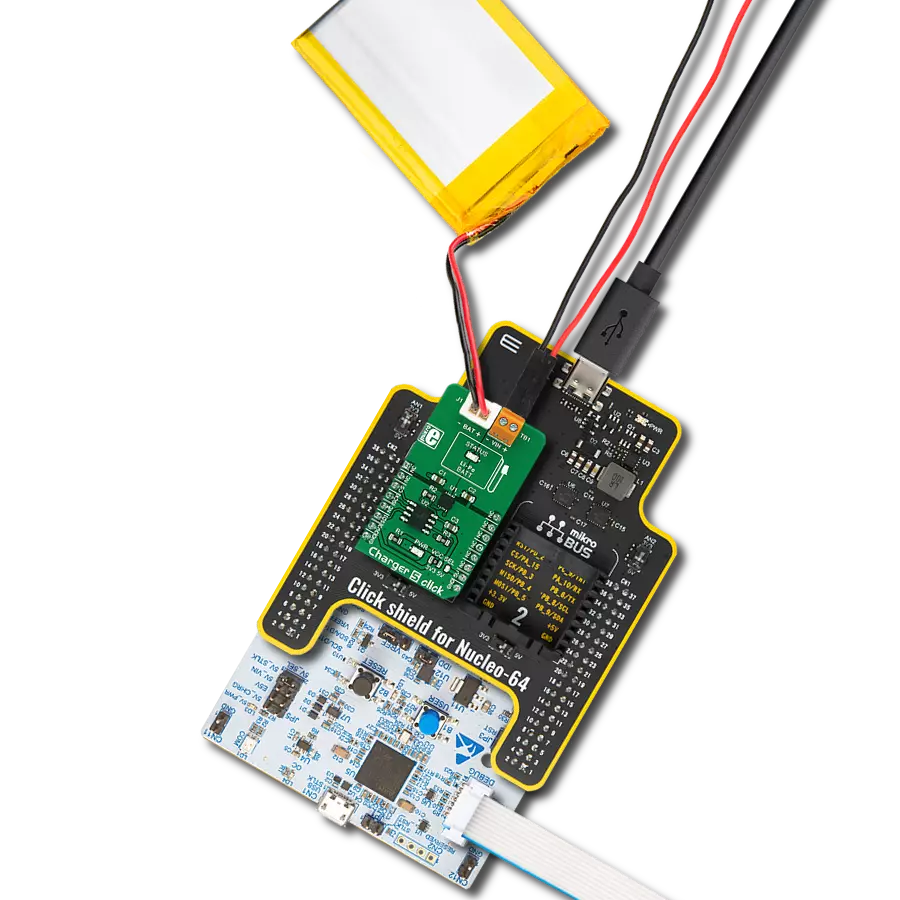
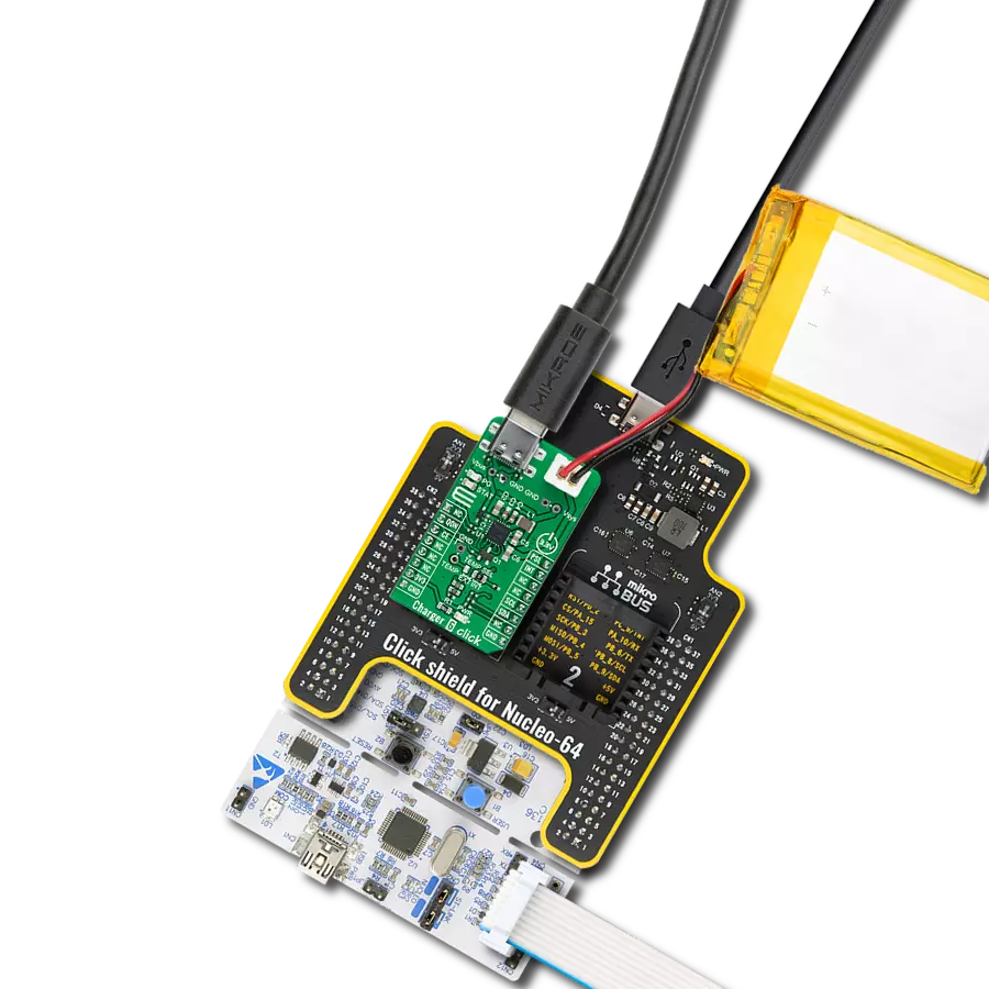
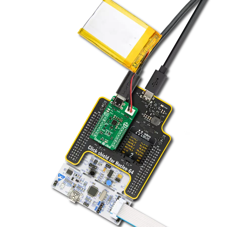
Project assembly
Start by selecting your development board and Click board™. Begin with the Nucleo-64 with STM32F030R8 MCU as your development board.


Track your results in real time
Application Output
1. Application Output - In Debug mode, the 'Application Output' window enables real-time data monitoring, offering direct insight into execution results. Ensure proper data display by configuring the environment correctly using the provided tutorial.

2. UART Terminal - Use the UART Terminal to monitor data transmission via a USB to UART converter, allowing direct communication between the Click board™ and your development system. Configure the baud rate and other serial settings according to your project's requirements to ensure proper functionality. For step-by-step setup instructions, refer to the provided tutorial.

3. Plot Output - The Plot feature offers a powerful way to visualize real-time sensor data, enabling trend analysis, debugging, and comparison of multiple data points. To set it up correctly, follow the provided tutorial, which includes a step-by-step example of using the Plot feature to display Click board™ readings. To use the Plot feature in your code, use the function: plot(*insert_graph_name*, variable_name);. This is a general format, and it is up to the user to replace 'insert_graph_name' with the actual graph name and 'variable_name' with the parameter to be displayed.

Software Support
Library Description
This library contains API for Charger 5 Click driver.
Key functions:
charger5_generic_write- Generic write functioncharger5_generic_read-Generic read functioncharger5_increment_wiper- Increment wiper function
Open Source
Code example
The complete application code and a ready-to-use project are available through the NECTO Studio Package Manager for direct installation in the NECTO Studio. The application code can also be found on the MIKROE GitHub account.
/*!
 * \file main.c
 * \brief Charger 5 Click example
 *
 * # Description
 * This example demonstrates the use of the Charger 5 Click board.
 *
 * The demo application is composed of two sections :
 *
 * ## Application Init
 * Initializes peripherals and pins used for the Charger 5 Click and prepares
 * the Charger 5 Click for properly working.
 *
 * ## Application Task
 * Demonstrates the use of driver functions. It will set charging current to
 * 500 mA, then will increment that value by 10 steps, and after that will
 * decrement it by 5 steps.
 *
 * ## Note
 * Increment/decrement command can only be issued to volatile memory locations.
 *
 * \author Nemanja Medakovic
 *
 */
// ------------------------------------------------------------------- INCLUDES

#include "board.h"
#include "log.h"
#include "charger5.h"

// ------------------------------------------------------------------ VARIABLES

static charger5_t charger5;
static log_t console;

// ------------------------------------------------------ APPLICATION FUNCTIONS

void application_init( void )
{
    charger5_cfg_t charger5_cfg;
    log_cfg_t console_cfg;

    //  Click initialization.
    charger5_cfg_setup( &charger5_cfg );
    CHARGER5_MAP_MIKROBUS( charger5_cfg, MIKROBUS_1 );
    charger5_init( &charger5, &charger5_cfg );
    charger5_default_cfg( &charger5 );

    /**
     * Logger initialization.
     * Default baud rate: 115200
     * Default log level: LOG_LEVEL_DEBUG
     * @note If USB_UART_RX and USB_UART_TX
     * are defined as HAL_PIN_NC, you will
     * need to define them manually for log to work.
     * See @b LOG_MAP_USB_UART macro definition for detailed explanation.
     */
    LOG_MAP_USB_UART( console_cfg );
    log_init( &console, &console_cfg );
    log_printf( &console, "***  Charger 5 initialization done  ***\r\n" );
    log_printf( &console, "***************************************\r\n" );
}

void application_task( void )
{
    charger5_generic_write( &charger5, CHARGER5_REG_WIPER0_VOL,
                            CHARGER5_CURRENT_500MA );
    log_printf( &console, "Output current is set to 500 mA.\r\n" );
    Delay_ms ( 1000 );
    Delay_ms ( 1000 );
    Delay_ms ( 1000 );

    charger5_increment_wiper( &charger5, CHARGER5_REG_WIPER0_VOL,
                              CHARGER5_STEPS_10 );
    log_printf( &console, "Output current value is incremented by 10 steps.\r\n" );
    Delay_ms ( 1000 );
    Delay_ms ( 1000 );
    Delay_ms ( 1000 );

    charger5_decrement_wiper( &charger5, CHARGER5_REG_WIPER0_VOL,
                              CHARGER5_STEPS_5 );
    log_printf( &console, "Output current value is decremented by 5 steps.\r\n" );
    Delay_ms ( 1000 );
    Delay_ms ( 1000 );
    Delay_ms ( 1000 );
}

int main ( void )
{
    /* Do not remove this line or clock might not be set correctly. */
    #ifdef PREINIT_SUPPORTED
    preinit();
    #endif

    application_init( );

    for ( ; ; )
    {
        application_task( );
    }

    return 0;
}


// ------------------------------------------------------------------------ END
Additional Support
Resources
Category:Battery charger