Receive real-time alerts about air quality changes using BME688 and STM32F103RB
Your partner in humidity balance and air quality brilliance

Published Oct 08, 2024
Click board™
Environment 3 Click
Dev. board
Nucleo 64 with STM32F103RB MCU
Compiler
NECTO Studio
MCU
STM32F103RB
Craft environments that strike the perfect balance between comfort and health by using precise humidity and air quality data to inform your adjustments
A
A
Hardware Overview
How does it work?
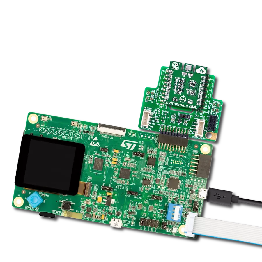
Environment 3 Click is based on the BME688, air quality MEMS sensor that combines gas, humidity, temperature, and barometric pressure sensing from Bosch Sensortec. The BME688 combines reliable high-precision sensors with wide-ranging gas detection and innovative AI capabilities, enabling users to rapidly develop various applications to improve well-being, lifestyle, and sustainability. It offers reduced power consumption, improved accuracy specifications, and a configurable host interface for the fastest data transfer. It covers extended operating pressure, humidity, and temperature ranges from 300-1100hPa, 0-100%RH and from -40°C to +85°C with the accuracy of ±3%RH and ±0.5°C. The BME688 supports a full suite of operational modes, which provides vast flexibility in optimizing
the device for power consumption, resolution, and filter performance. Additionally, it also has a gas scanner function; it can detect Volatile Organic Compounds (VOCs), Volatile Sulfur Compounds (VSCs), and other gases such as carbon monoxide and hydrogen in the part per billion (ppb) range. In standard configuration, the presence of VSCs is being detected as an indicator for, e.g., bacteria growth, where the gas scanner can be customized for sensitivity, selectivity, data rate, and power consumption. Based on its main features listed above, this Click board is the best choice for indoor and outdoor air quality measurement applications, detection of unusual gases that might indicate leakage or fire, early detection of odors and bad smells, and other various temperature and humidity-related applications. Environment 3 Click
allows using both I2C and SPI interfaces. The selection can be made by positioning SMD jumpers labeled COMM SEL in an appropriate position. Note that all the jumpers' positions must be on the same side, or the Click board™ may become unresponsive. While the I2C interface is selected, the BME688 allows choosing the least significant bit (LSB) of its I2C slave address using the SMD jumper labeled ADDR SEL to an appropriate position marked as 0 or 1. This Click board™ can be operated only with a 3.3V logic voltage level. The board must perform appropriate logic voltage level conversion before using MCUs with different logic levels. Also, it comes equipped with a library containing functions and an example code that can be used, as a reference, for further development.


Features overview
Development board
Nucleo-64 with STM32F103RB MCU offers a cost-effective and adaptable platform for developers to explore new ideas and prototype their designs. This board harnesses the versatility of the STM32 microcontroller, enabling users to select the optimal balance of performance and power consumption for their projects. It accommodates the STM32 microcontroller in the LQFP64 package and includes essential components such as a user LED, which doubles as an ARDUINO® signal, alongside user and reset push-buttons, and a 32.768kHz crystal oscillator for precise timing operations. Designed with expansion and flexibility in mind, the Nucleo-64 board features an ARDUINO® Uno V3 expansion connector and ST morpho extension pin
headers, granting complete access to the STM32's I/Os for comprehensive project integration. Power supply options are adaptable, supporting ST-LINK USB VBUS or external power sources, ensuring adaptability in various development environments. The board also has an on-board ST-LINK debugger/programmer with USB re-enumeration capability, simplifying the programming and debugging process. Moreover, the board is designed to simplify advanced development with its external SMPS for efficient Vcore logic supply, support for USB Device full speed or USB SNK/UFP full speed, and built-in cryptographic features, enhancing both the power efficiency and security of projects. Additional connectivity is
provided through dedicated connectors for external SMPS experimentation, a USB connector for the ST-LINK, and a MIPI® debug connector, expanding the possibilities for hardware interfacing and experimentation. Developers will find extensive support through comprehensive free software libraries and examples, courtesy of the STM32Cube MCU Package. This, combined with compatibility with a wide array of Integrated Development Environments (IDEs), including IAR Embedded Workbench®, MDK-ARM, and STM32CubeIDE, ensures a smooth and efficient development experience, allowing users to fully leverage the capabilities of the Nucleo-64 board in their projects.

Microcontroller Overview
MCU Card / MCU

Architecture
ARM Cortex-M3
MCU Memory (KB)
128
Silicon Vendor
STMicroelectronics
Pin count
64
RAM (Bytes)
20480
You complete me!
Accessories
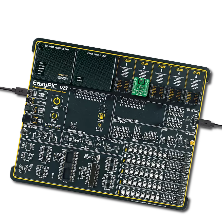
Click Shield for Nucleo-64 comes equipped with two proprietary mikroBUS™ sockets, allowing all the Click board™ devices to be interfaced with the STM32 Nucleo-64 board with no effort. This way, Mikroe allows its users to add any functionality from our ever-growing range of Click boards™, such as WiFi, GSM, GPS, Bluetooth, ZigBee, environmental sensors, LEDs, speech recognition, motor control, movement sensors, and many more. More than 1537 Click boards™, which can be stacked and integrated, are at your disposal. The STM32 Nucleo-64 boards are based on the microcontrollers in 64-pin packages, a 32-bit MCU with an ARM Cortex M4 processor operating at 84MHz, 512Kb Flash, and 96KB SRAM, divided into two regions where the top section represents the ST-Link/V2 debugger and programmer while the bottom section of the board is an actual development board. These boards are controlled and powered conveniently through a USB connection to program and efficiently debug the Nucleo-64 board out of the box, with an additional USB cable connected to the USB mini port on the board. Most of the STM32 microcontroller pins are brought to the IO pins on the left and right edge of the board, which are then connected to two existing mikroBUS™ sockets. This Click Shield also has several switches that perform functions such as selecting the logic levels of analog signals on mikroBUS™ sockets and selecting logic voltage levels of the mikroBUS™ sockets themselves. Besides, the user is offered the possibility of using any Click board™ with the help of existing bidirectional level-shifting voltage translators, regardless of whether the Click board™ operates at a 3.3V or 5V logic voltage level. Once you connect the STM32 Nucleo-64 board with our Click Shield for Nucleo-64, you can access hundreds of Click boards™, working with 3.3V or 5V logic voltage levels.

Used MCU Pins
mikroBUS™ mapper
Take a closer look
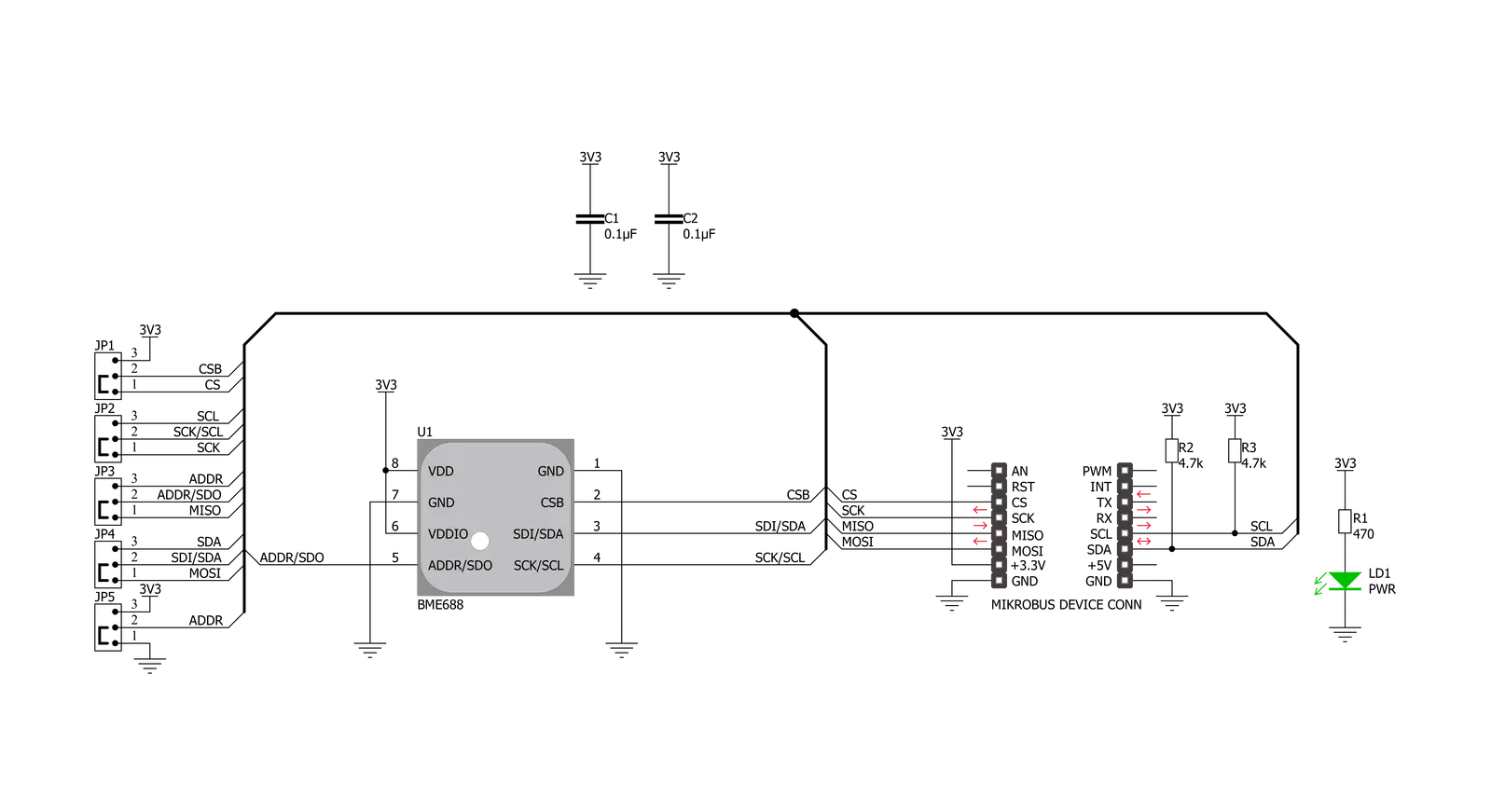
Click board™ Schematic
Step by step
Project assembly
Start by selecting your development board and Click board™. Begin with the Nucleo 64 with STM32F103RB MCU as your development board.


Track your results in real time
Application Output
1. Application Output - In Debug mode, the 'Application Output' window enables real-time data monitoring, offering direct insight into execution results. Ensure proper data display by configuring the environment correctly using the provided tutorial.

2. UART Terminal - Use the UART Terminal to monitor data transmission via a USB to UART converter, allowing direct communication between the Click board™ and your development system. Configure the baud rate and other serial settings according to your project's requirements to ensure proper functionality. For step-by-step setup instructions, refer to the provided tutorial.

3. Plot Output - The Plot feature offers a powerful way to visualize real-time sensor data, enabling trend analysis, debugging, and comparison of multiple data points. To set it up correctly, follow the provided tutorial, which includes a step-by-step example of using the Plot feature to display Click board™ readings. To use the Plot feature in your code, use the function: plot(*insert_graph_name*, variable_name);. This is a general format, and it is up to the user to replace 'insert_graph_name' with the actual graph name and 'variable_name' with the parameter to be displayed.

Software Support
Library Description
This library contains API for Environment 3 Click driver.
Key functions:
environment3_get_all_data- This function reads the temperature, humidity, pressure, and gas resistance data from the sensorenvironment3_enable_heater- This function enables or disables the gas sensor heaterenvironment3_soft_reset- This function soft-resets the sensor
Open Source
Code example
The complete application code and a ready-to-use project are available through the NECTO Studio Package Manager for direct installation in the NECTO Studio. The application code can also be found on the MIKROE GitHub account.
/*!
 * @file main.c
 * @brief Environment3 Click example
 *
 * # Description
 * This example demonstrates the use of Environment 3 Click board.
 *
 * The demo application is composed of two sections :
 *
 * ## Application Init
 * Initializes the driver, sets the default configuration, and disables the gas sensor heater.
 *
 * ## Application Task
 * Reads the temperature, humidity, pressure, and gas resistance data from the sensor and
 * displays all values on the USB UART approximately every second.
 *
 * @note
 * The heater is disabled by default, enable it in the Application Init if you need gas resistance data.
 * Gas resistance data is RAW data, if you need VOCs, please contact Bosch Sensortec for VOC calculation library.
 * The temperature and humidity data don't represent the real environmental data when the heater is enabled.
 *
 * @author Stefan Filipovic
 *
 */

#include "board.h"
#include "log.h"
#include "environment3.h"

static environment3_t environment3;
static log_t logger;

void application_init ( void )
{
    log_cfg_t log_cfg;                    /**< Logger config object. */
    environment3_cfg_t environment3_cfg;  /**< Click config object. */

    /**
     * Logger initialization.
     * Default baud rate: 115200
     * Default log level: LOG_LEVEL_DEBUG
     * @note If USB_UART_RX and USB_UART_TX
     * are defined as HAL_PIN_NC, you will
     * need to define them manually for log to work.
     * See @b LOG_MAP_USB_UART macro definition for detailed explanation.
     */
    LOG_MAP_USB_UART( log_cfg );
    log_init( &logger, &log_cfg );
    log_info( &logger, " Application Init " );

    // Click initialization.

    environment3_cfg_setup( &environment3_cfg );
    ENVIRONMENT3_MAP_MIKROBUS( environment3_cfg, MIKROBUS_1 );
    err_t init_flag  = environment3_init( &environment3, &environment3_cfg );
    if ( ( I2C_MASTER_ERROR == init_flag ) || ( SPI_MASTER_ERROR == init_flag ) )
    {
        log_error( &logger, " Application Init Error. " );
        log_info( &logger, " Please, run program again... " );

        for ( ; ; );
    }

    if ( ENVIRONMENT3_OK != environment3_default_cfg ( &environment3 ) )
    {
        log_error( &logger, " Default Config Error. " );
        log_info( &logger, " Please, run program again... " );

        for ( ; ; );
    }

    environment3_enable_heater ( &environment3, ENVIRONMENT3_DISABLE );
    log_info( &logger, " Application Task " );
}

void application_task ( void )
{
    float temperature, pressure, humidity;
    uint32_t gas_resistance;
    if ( ENVIRONMENT3_OK == environment3_get_all_data ( &environment3,
                                                        &temperature,
                                                        &humidity,
                                                        &pressure,
                                                        &gas_resistance ) )
    {
        log_printf( &logger, " Temperature : %.2f C\r\n", temperature );

        log_printf( &logger, " Humidity : %.2f %%\r\n", humidity );

        log_printf( &logger, " Pressure : %.3f mBar\r\n", pressure );

        if ( ENVIRONMENT3_ENABLE == environment3.gas_sett.enable )
        {
            log_printf( &logger, " Gas Resistance : %ld Ohms\r\n", gas_resistance );
            log_printf( &logger, "--------------------------------\r\n" );
        }
        else
        {
            log_printf( &logger, "--------------------------------\r\n" );
            Delay_ms ( 1000 );
        }
    }
}

int main ( void )
{
    /* Do not remove this line or clock might not be set correctly. */
    #ifdef PREINIT_SUPPORTED
    preinit();
    #endif

    application_init( );

    for ( ; ; )
    {
        application_task( );
    }

    return 0;
}

// ------------------------------------------------------------------------ END
Additional Support
Resources
Category:Environmental