Witness the future of connectivity with ESP8684-MINI-1 and STM32F091RC
A game-changer in wireless solutions, designed to redefine the way you connect

Published Feb 26, 2024
Click board™
ESP8684 Click
Dev. board
Nucleo-64 with STM32F091RC MCU
Compiler
NECTO Studio
MCU
STM32F091RC
Our wireless combo solution harmonizes the strengths of WiFi and BLE, creating a symphony of connectivity for a smarter, more efficient world.
A
A
Hardware Overview
How does it work?
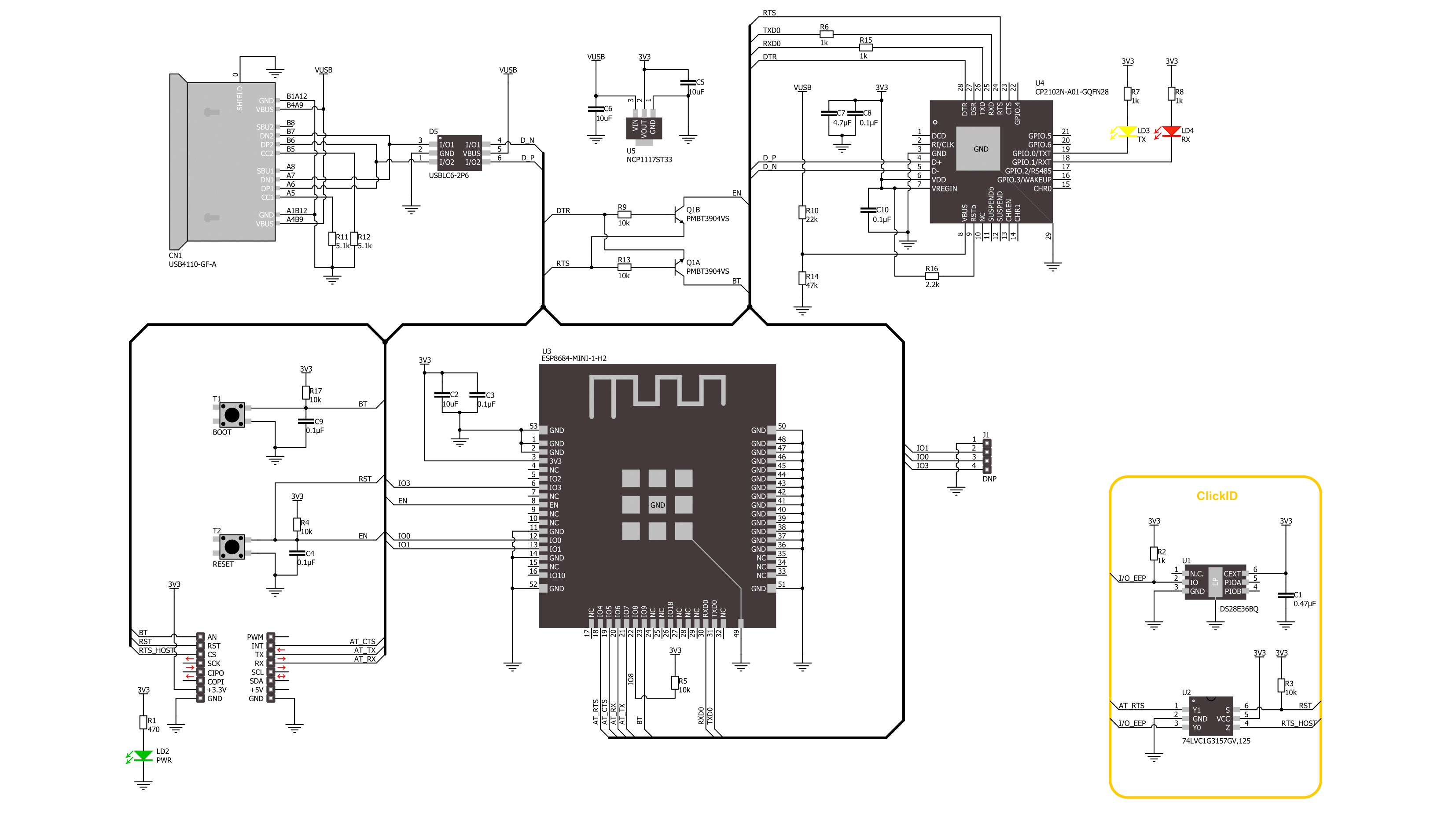
ESP8684 Click is based on the ESP8684-MINI-1, a highly integrated WiFi, and a Bluetooth 5 module from Espressif Systems. It is based on the ESP8684H2 embedded 32-bit RISC-V single-core processor operating at up to 120MHz frequency. The processor also has an on-chip 576KB of ROM and 272KB of SRAM memory, supporting flash in-circuit programming (ICP). It also features an internal co-existence mechanism between WiFi and Bluetooth to share the same printed PCB antenna. The downside is that you can’t use both WiFi and Bluetooth at the same time. ESP8684 Click is an IEEE802.11b/g/n-compliant and supports 20MHz bandwidth in the 2.4GHz band. In 1T1R mode, it can achieve data rates of up to 72.2Mbps. In addition, the module supports WiFi Multimedia (WMM), fragmentation and defragmentation, transmit opportunity (TXOP), automatic beacon monitoring hardware (hardware TSF), and more. As for Bluetooth, the module can achieve
speeds of 125kbps, 500kbps, 1Mbps, and 2Mbps. The security features secure boot, flash encryption, 1024-bit OTP up to 256 bits for use, cryptographic hardware acceleration, and more. This Click board™ is equipped with a USB type C connector and circuits that allow you to establish direct communication between the ESP8684 module and a PC. This communication can be used for testing purposes or for upgrading the software. For uploading software to the ESP8684 module, there is an auto-reset circuit and the CP2102N, a USB-to-UART bridge from Silicon Labs. Two LEDs, RX and TX, are there to visually confirm the data exchange over this bridge. In addition, two buttons, RESET and BOOT, allow you to enter the ESP8684’s boot mode. Finally, a header contains 3 GPIOs and a GND for user configuration and can be used for an analog interface. ESP8684 Click uses a standard 2-Wire UART interface to communicate with the host MCU with commonly
used UART RTS and CTS control flow pins. Besides the available software and libraries we provide, you can use a set of AT commands to program the ESP8684 module. In addition to the UART bridge and two onboard buttons, you can enter the ESP8684’s boot mode via RST and BT pins of the mikroBUS™ socket. Thanks to the onboard NCP1117 LDO, which converts USB voltage into the 3.3V necessary for operation, this board can be standalone independent of the mikroBUS™ socket. This Click board™ can be operated only with a 3.3V logic voltage level. The board must perform appropriate logic voltage level conversion before using MCUs with different logic levels. Also, this Click board™ comes equipped with a library containing easy-to-use functions and an example code that can be used as a reference for further development.

Features overview
Development board
Nucleo-64 with STM32F091RC MCU offers a cost-effective and adaptable platform for developers to explore new ideas and prototype their designs. This board harnesses the versatility of the STM32 microcontroller, enabling users to select the optimal balance of performance and power consumption for their projects. It accommodates the STM32 microcontroller in the LQFP64 package and includes essential components such as a user LED, which doubles as an ARDUINO® signal, alongside user and reset push-buttons, and a 32.768kHz crystal oscillator for precise timing operations. Designed with expansion and flexibility in mind, the Nucleo-64 board features an ARDUINO® Uno V3 expansion connector and ST morpho extension pin
headers, granting complete access to the STM32's I/Os for comprehensive project integration. Power supply options are adaptable, supporting ST-LINK USB VBUS or external power sources, ensuring adaptability in various development environments. The board also has an on-board ST-LINK debugger/programmer with USB re-enumeration capability, simplifying the programming and debugging process. Moreover, the board is designed to simplify advanced development with its external SMPS for efficient Vcore logic supply, support for USB Device full speed or USB SNK/UFP full speed, and built-in cryptographic features, enhancing both the power efficiency and security of projects. Additional connectivity is
provided through dedicated connectors for external SMPS experimentation, a USB connector for the ST-LINK, and a MIPI® debug connector, expanding the possibilities for hardware interfacing and experimentation. Developers will find extensive support through comprehensive free software libraries and examples, courtesy of the STM32Cube MCU Package. This, combined with compatibility with a wide array of Integrated Development Environments (IDEs), including IAR Embedded Workbench®, MDK-ARM, and STM32CubeIDE, ensures a smooth and efficient development experience, allowing users to fully leverage the capabilities of the Nucleo-64 board in their projects.

Microcontroller Overview
MCU Card / MCU

Architecture
ARM Cortex-M0
MCU Memory (KB)
256
Silicon Vendor
STMicroelectronics
Pin count
64
RAM (Bytes)
32768
You complete me!
Accessories
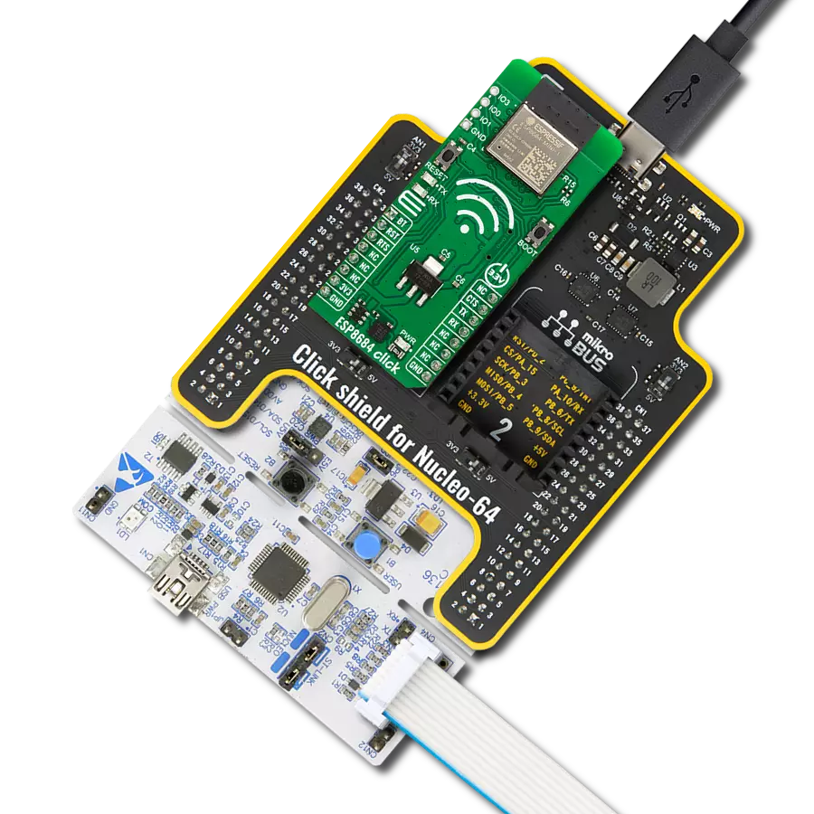
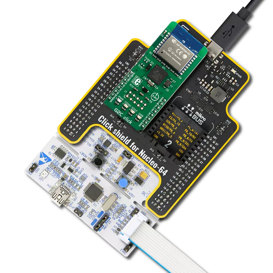
Click Shield for Nucleo-64 comes equipped with two proprietary mikroBUS™ sockets, allowing all the Click board™ devices to be interfaced with the STM32 Nucleo-64 board with no effort. This way, Mikroe allows its users to add any functionality from our ever-growing range of Click boards™, such as WiFi, GSM, GPS, Bluetooth, ZigBee, environmental sensors, LEDs, speech recognition, motor control, movement sensors, and many more. More than 1537 Click boards™, which can be stacked and integrated, are at your disposal. The STM32 Nucleo-64 boards are based on the microcontrollers in 64-pin packages, a 32-bit MCU with an ARM Cortex M4 processor operating at 84MHz, 512Kb Flash, and 96KB SRAM, divided into two regions where the top section represents the ST-Link/V2 debugger and programmer while the bottom section of the board is an actual development board. These boards are controlled and powered conveniently through a USB connection to program and efficiently debug the Nucleo-64 board out of the box, with an additional USB cable connected to the USB mini port on the board. Most of the STM32 microcontroller pins are brought to the IO pins on the left and right edge of the board, which are then connected to two existing mikroBUS™ sockets. This Click Shield also has several switches that perform functions such as selecting the logic levels of analog signals on mikroBUS™ sockets and selecting logic voltage levels of the mikroBUS™ sockets themselves. Besides, the user is offered the possibility of using any Click board™ with the help of existing bidirectional level-shifting voltage translators, regardless of whether the Click board™ operates at a 3.3V or 5V logic voltage level. Once you connect the STM32 Nucleo-64 board with our Click Shield for Nucleo-64, you can access hundreds of Click boards™, working with 3.3V or 5V logic voltage levels.

Used MCU Pins
mikroBUS™ mapper
Take a closer look
Click board™ Schematic
Step by step
Project assembly
Start by selecting your development board and Click board™. Begin with the Nucleo-64 with STM32F091RC MCU as your development board.


Software Support
Library Description
This library contains API for ESP8684 Click driver.
Key functions:
esp8684_send_cmd- ESP8684 send command with arguments function.esp8684_send_query_cmd- ESP8684 send query command function.esp8684_connect_to_network- ESP8684 connect to network function.
Open Source
Code example
The complete application code and a ready-to-use project are available through the NECTO Studio Package Manager for direct installation in the NECTO Studio. The application code can also be found on the MIKROE GitHub account.
/*!
 * @file main.c
 * @brief ESP8684 Click Example.
 *
 * # Description
 * This example connects to the desired WiFi network and then
 * connects to the TCP/UDP server, writes then reads data to and from it.
 *
 * The demo application is composed of two sections :
 *
 * ## Application Init
 * Initializes driver and wifi communication, then connects to the desired WiFi network
 * and sends data to the TCP/UDP server.
 *
 * ## Application Task
 * Writes and reads data from TCP/UDP server, processes all incoming data
 * and displays them on the USB UART.
 *
 * ## Additional Function
 * - void esp8684_clear_app_buf ( void )
 * - void esp8684_log_app_buf ( void )
 * - err_t esp8684_process ( void )
 * - err_t esp8684_rsp_check ( uint8_t *response )
 * - void esp8684_error_check( err_t error_flag )
 * - void esp8684_send_message ( uint8_t *link_id, uint8_t *message )
 * - void esp8684_con_device_to_network ( void )
 * - void esp8684_send_data ( void )
 *
 * @author Stefan Ilic
 *
 */

#include "board.h"
#include "log.h"
#include "esp8684.h"
#include "string.h"
#include "conversions.h"

#define PROCESS_BUFFER_SIZE 200

#define ESP8684_SSID                        "MikroE Public"
#define ESP8684_PASSWORD                    "mikroe.guest"

#define ESP8684_DATA                        "MikroE ESP8684 Click"

// TCP/UDP example parameters
#define REMOTE_IP                           "77.46.162.162" // TCP/UDP echo server IP address
#define REMOTE_PORT                         "51111"         // TCP/UDP echo server port
#define TCP_LINK_ID                         "0"             // TCP link ID
#define UDP_LINK_ID                         "1"             // UDP link ID

esp8684_t esp8684;
log_t logger;

uint8_t app_buf[ PROCESS_BUFFER_SIZE ] = { 0 };
int32_t app_buf_len = 0;

err_t app_error_flag;

/**
 * @brief ESP8684 clearing application buffer.
 * @details This function clears memory of application buffer and reset its length.
 * @return Nothing.
 * @note None.
 */
void esp8684_clear_app_buf ( void );

/**
 * @brief ESP8684 log application buffer.
 * @details This function logs application buffer and reset its length.
 * @return Nothing.
 * @note None.
 */
void esp8684_log_app_buf ( void );

/**
 * @brief ESP8684 data reading function.
 * @details This function reads data from device and concatenates data to application buffer.
 * @return @li @c  0 - Read some data.
 *         @li @c -1 - Nothing is read.
 * See #err_t definition for detailed explanation.
 * @note None.
 */
err_t esp8684_process ( void );

/**
 * @brief ESP8684 response check function.
 * @details This function checks the response of the sent command.
 * @param[in] response : Expected response.
 * @return @li @c  0 - Responded as expected.
 *         @li @c -1 - The response isn't the same..
 * See #err_t definition for detailed explanation.
 * @note None.
 */
err_t esp8684_rsp_check ( uint8_t *response );

/**
 * @brief ESP8684 error check function.
 * @details This function checks if error has occurred.
 * @param[in] error_flag : Data to be checked.
 * @return Nothing.
 * @note None.
 */
void esp8684_error_check( err_t error_flag );

/**
 * @brief ESP8684 send message function.
 * @details This function is used to send messages to the host.
 * @param[in] link_id : Host link id.
 * @param[in] message : Message to be sent.
 * @return Nothing.
 * @note None.
 */
void esp8684_send_message ( uint8_t *link_id, uint8_t *message );

/**
 * @brief ESP8684 connect device to the network.
 * @details This function is used to connect device to network.
 * @return Nothing.
 * @note None.
 */
void esp8684_con_device_to_network ( void );

/**
 * @brief ESP8684 send message to the host.
 * @details This function is used to send messages to the host.
 * @return Nothing.
 * @note None.
 */
void esp8684_send_data ( void );

void application_init ( void )
{
    log_cfg_t log_cfg;  /**< Logger config object. */
    esp8684_cfg_t esp8684_cfg;  /**< Click config object. */

    /**
     * Logger initialization.
     * Default baud rate: 115200
     * Default log level: LOG_LEVEL_DEBUG
     * @note If USB_UART_RX and USB_UART_TX
     * are defined as HAL_PIN_NC, you will
     * need to define them manually for log to work.
     * See @b LOG_MAP_USB_UART macro definition for detailed explanation.
     */
    LOG_MAP_USB_UART( log_cfg );
    log_init( &logger, &log_cfg );
    log_info( &logger, " Application Init " );

    // Click initialization.
    esp8684_cfg_setup( &esp8684_cfg );
    ESP8684_MAP_MIKROBUS( esp8684_cfg, MIKROBUS_1 );
    if ( UART_ERROR == esp8684_init( &esp8684, &esp8684_cfg ) )
    {
        log_error( &logger, " Communication init." );
        for ( ; ; );
    }

    esp8684_default_cfg( &esp8684 );
    Delay_ms ( 1000 );
    Delay_ms ( 1000 );
    Delay_ms ( 1000 );

    esp8684_process( );
    esp8684_clear_app_buf( );

    esp8684_send_cmd( &esp8684, ESP8684_CMD_AT, NULL );
    app_error_flag = esp8684_rsp_check( ESP8684_RSP_OK );
    esp8684_error_check( app_error_flag );
    Delay_ms ( 500 );

    esp8684_send_cmd( &esp8684, ESP8684_CMD_RST, NULL );
    app_error_flag = esp8684_rsp_check( ESP8684_RSP_READY );
    esp8684_error_check( app_error_flag );
    Delay_ms ( 500 );
    esp8684_process( );
    esp8684_clear_app_buf();

    esp8684_send_cmd( &esp8684, ESP8684_CMD_GMR, NULL );
    app_error_flag = esp8684_rsp_check( ESP8684_RSP_OK );
    esp8684_error_check( app_error_flag );
    Delay_ms ( 500 );

    // Communication initialization
    esp8684_con_device_to_network ( );

    log_info( &logger, " Application Task " );
}

void application_task ( void )
{
    log_printf( &logger, "Sending and reading data from the TCP/UDP server \r\n" );
    esp8684_send_data( );
    Delay_ms ( 1000 );
    Delay_ms ( 1000 );
    Delay_ms ( 1000 );
    Delay_ms ( 1000 );
    Delay_ms ( 1000 );
}

int main ( void )
{
    /* Do not remove this line or clock might not be set correctly. */
    #ifdef PREINIT_SUPPORTED
    preinit();
    #endif

    application_init( );

    for ( ; ; )
    {
        application_task( );
    }

    return 0;
}

void esp8684_clear_app_buf ( void )
{
    memset( app_buf, 0, app_buf_len );
    app_buf_len = 0;
}

void esp8684_log_app_buf ( void )
{
    for ( int32_t buf_cnt = 0; buf_cnt < app_buf_len; buf_cnt++ )
    {
        log_printf( &logger, "%c", app_buf[ buf_cnt ] );
    }
    esp8684_clear_app_buf(  );
}

err_t esp8684_process ( void )
{
    err_t return_flag = ESP8684_ERROR;
    int32_t rx_size;
    uint8_t rx_buff[ ESP8684_RX_DRV_BUFFER_SIZE ] = { 0 };

    rx_size = esp8684_generic_read( &esp8684, rx_buff, ESP8684_RX_DRV_BUFFER_SIZE );

    if ( rx_size > 0 )
    {
        int32_t buf_cnt = 0;
        return_flag = ESP8684_OK;

        if ( app_buf_len + rx_size >= ESP8684_RX_DRV_BUFFER_SIZE )
        {
            esp8684_clear_app_buf( );
            return_flag = ESP8684_OVERFLOW;
        }
        else
        {
            buf_cnt = app_buf_len;
            app_buf_len += rx_size;
        }

        for ( int32_t rx_cnt = 0; rx_cnt < rx_size; rx_cnt++ )
        {
            if ( rx_buff[ rx_cnt ] != 0 )
            {
                app_buf[ ( buf_cnt + rx_cnt ) ] = rx_buff[ rx_cnt ];
            }
            else
            {
                buf_cnt--;
                app_buf_len--;
            }
        }
    }

    return return_flag;
}

err_t esp8684_rsp_check ( uint8_t *response )
{
    uint16_t timeout_cnt = 0;
    uint16_t timeout = 50000;
    err_t error_flag = esp8684_process( );
    if ( ( error_flag != ESP8684_OK ) && ( error_flag != ESP8684_ERROR ) )
    {
        return error_flag;
    }

    while ( ( strstr( app_buf, response ) == 0 ) && ( strstr( app_buf, ESP8684_RSP_ERROR ) == 0 ) )
    {
        error_flag = esp8684_process( );
        if ( ( error_flag != ESP8684_OK ) && ( error_flag != ESP8684_ERROR ) )
        {
            return error_flag;
        }

        timeout_cnt++;

        if ( timeout_cnt > timeout )
        {
            esp8684_clear_app_buf( );
            return ESP8684_TIMEOUT;
        }
        Delay_ms ( 1 );
    }
    esp8684_log_app_buf();

    return ESP8684_OK;
}

void esp8684_error_check( err_t error_flag )
{
    if ( ( ESP8684_OK != error_flag ) && ( error_flag != ESP8684_ERROR ) )
    {
        switch ( error_flag )
        {
            case ( ESP8684_OVERFLOW ):
                log_error( &logger, " Overflow!" );
                break;
            case ( ESP8684_TIMEOUT ):
                log_error( &logger, " Timeout!" );
                break;
            default:
                break;
        }
    }
    log_printf( &logger, "\r\n-----------------------------------\r\n" );
}

void esp8684_send_message ( uint8_t *link_id, uint8_t *message )
{
    uint8_t cmd_buf[ 100 ] = { 0 };
    uint8_t message_len_buf[ 5 ] = { 0 };
    uint16_t message_len = strlen( message );

    uint16_to_str( message_len, message_len_buf );
    l_trim( message_len_buf );
    r_trim( message_len_buf );
    strcpy( cmd_buf, link_id );
    strcat( cmd_buf, "," );
    strcat( cmd_buf, message_len_buf );
    esp8684_send_cmd( &esp8684, ESP8684_CMD_CIPSEND, cmd_buf );

    if ( ESP8684_OK == esp8684_rsp_check( ESP8684_READY_FOR_SEND ) )
    {
        esp8684_generic_write( &esp8684, message, strlen(message) );
        esp8684_generic_write( &esp8684, "\032", 1 );
    }
}

void esp8684_con_device_to_network ( void )
{
    esp8684_send_cmd( &esp8684, ESP8684_CMD_CWMODE, "1" );
    app_error_flag = esp8684_rsp_check( ESP8684_RSP_OK );
    esp8684_error_check( app_error_flag );
    Delay_ms ( 500 );

    esp8684_connect_to_network( &esp8684, ESP8684_SSID, ESP8684_PASSWORD );
    app_error_flag = esp8684_rsp_check( ESP8684_RSP_OK );
    esp8684_error_check( app_error_flag );
    Delay_ms ( 500 );

    esp8684_send_cmd( &esp8684, ESP8684_CMD_CIPMUX, "1" );
    app_error_flag = esp8684_rsp_check( ESP8684_RSP_OK );
    esp8684_error_check( app_error_flag );
    Delay_ms ( 500 );

    esp8684_send_cmd( &esp8684, ESP8684_CMD_CIPRECVMODE, "0" );
    app_error_flag = esp8684_rsp_check( ESP8684_RSP_OK );
    esp8684_error_check( app_error_flag );
    Delay_ms ( 500 );

    esp8684_send_query_cmd( &esp8684, ESP8684_CMD_CIPSTATE );
    app_error_flag = esp8684_rsp_check( ESP8684_RSP_OK );
    esp8684_error_check( app_error_flag );
    Delay_ms ( 500 );
}

void esp8684_send_data ( void )
{
    esp8684_connect_for_trans( &esp8684, "TCP", TCP_LINK_ID, REMOTE_IP, REMOTE_PORT );
    app_error_flag = esp8684_rsp_check( ESP8684_RSP_OK );
    esp8684_error_check( app_error_flag );
    Delay_ms ( 500 );

    esp8684_connect_for_trans( &esp8684, "UDP", UDP_LINK_ID, REMOTE_IP, REMOTE_PORT );
    app_error_flag = esp8684_rsp_check( ESP8684_RSP_OK );
    esp8684_error_check( app_error_flag );
    Delay_ms ( 500 );

    esp8684_send_message( TCP_LINK_ID, ESP8684_DATA );
    Delay_ms ( 500 );

    log_printf( &logger, "Read data TCP: \r\n" );
    app_error_flag = esp8684_rsp_check( ESP8684_RSP_RECEIVE );
    esp8684_error_check( app_error_flag );
    Delay_ms ( 1000 );

    esp8684_send_message( UDP_LINK_ID, ESP8684_DATA );
    Delay_ms ( 500 );

    log_printf( &logger, "Read data UDP: \r\n" );
    app_error_flag = esp8684_rsp_check( ESP8684_RSP_RECEIVE );
    esp8684_error_check( app_error_flag );
    Delay_ms ( 500 );

    esp8684_send_cmd( &esp8684, ESP8684_CMD_CIPCLOSE, TCP_LINK_ID );
    app_error_flag = esp8684_rsp_check( ESP8684_RSP_OK );
    esp8684_error_check( app_error_flag );
    Delay_ms ( 500 );

    esp8684_send_cmd( &esp8684, ESP8684_CMD_CIPCLOSE, UDP_LINK_ID );
    app_error_flag = esp8684_rsp_check( ESP8684_RSP_OK );
    esp8684_error_check( app_error_flag );
    Delay_ms ( 500 );
}

// ------------------------------------------------------------------------ END
Additional Support
Resources
Category:WiFi