Upgrade your I/O control with TCA6424A and STM32F334R8
From limited to limitless
Published Oct 08, 2024
Click board™
EXPAND 5 Click
Dev. board
Nucleo 64 with STM32F334R8 MCU
Compiler
NECTO Studio
MCU
STM32F334R8
Our port expander solution simplifies and amplifies your I/O capabilities, enabling seamless expansion of pins for diverse applications, from automation and IoT to robotics and prototyping
A
A
Hardware Overview
How does it work?
EXPAND 5 Click is based on the TCA6424A, low-voltage 24-bit I2C, and SMBus I/O expander from Texas Instruments. This 24-bit I/O expander for the two-line bidirectional bus is designed to provide general-purpose remote I/O expansion for most microcontroller families via the 400-kHz fast I2C bus. This Click board™ features on-board I2C address jumpers, pull-up resistors, power supply bypass capacitor, and power LED. It operates over a flexible power supply voltage range of 1.65V to 5.5V, which makes it suitable for 3.3V and 5V microcontrollers. At power-on, the I/O pins are configured as inputs. However, the microcontroller can enable the I/Os as either inputs or outputs by writing to the I/O configuration bits. The data for each input or output is kept in the corresponding input or output register. The polarity of the Input Port register can be inverted with the Polarity Inversion register. The microcontroller can reset the TCA6424A in the event of a timeout or other
improper operation by asserting a low in the RESET input. The power-on reset puts the registers in their default state and initializes the I2C interface. The RESET pin causes the same reset/initialization to occur without depowering the part. This Click board™ also has an open-drain interrupt (INT) output that is activated when any input state differs from its corresponding Input Port register state and is used to indicate to the microcontroller that an input state has changed. By sending an interrupt signal on this line, the remote I/O can inform the microcontroller if there is incoming data on its ports without having to communicate via the I2C bus. Thus, the TCA6424A can remain a simple slave device. The TCA6424A communicates with MCU using the standard I2C 2-wire interface. The TCA6424A can respond to one of two 7-bit I2C Bus Slave addresses. The first 6 bits (MSBs) have been factory programmed to 010001. The address pin, ADDR (Pin 26) is
programmed by the user and determines the LSB of the slave address and it can be selected by onboard SMD jumper labeled as ADDR SEL allowing selection of the slave address LSB. The last bit of the slave address defines the operation (read or write) to be performed. A high (1) selects a read operation, while a low (0) selects a write operation. This Click board™ can be supplied and interfaced with both 3.3V and 5V without the need for any external components. The onboard SMD jumper labeled as VCC SEL allows voltage selection for interfacing with both 3.3V and 5V microcontrollers. More information about the TCA6424A can be found in the attached datasheet. However, this Click board™ comes equipped with a library that contains easy to use functions and a usage example that may be used as a reference for the development.


Features overview
Development board
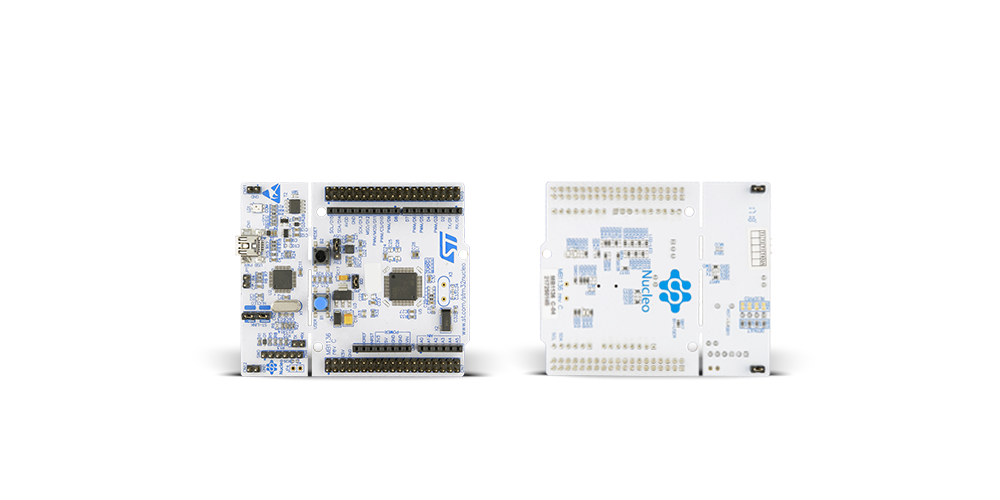
Nucleo-64 with STM32F334R8 MCU offers a cost-effective and adaptable platform for developers to explore new ideas and prototype their designs. This board harnesses the versatility of the STM32 microcontroller, enabling users to select the optimal balance of performance and power consumption for their projects. It accommodates the STM32 microcontroller in the LQFP64 package and includes essential components such as a user LED, which doubles as an ARDUINO® signal, alongside user and reset push-buttons, and a 32.768kHz crystal oscillator for precise timing operations. Designed with expansion and flexibility in mind, the Nucleo-64 board features an ARDUINO® Uno V3 expansion connector and ST morpho extension pin
headers, granting complete access to the STM32's I/Os for comprehensive project integration. Power supply options are adaptable, supporting ST-LINK USB VBUS or external power sources, ensuring adaptability in various development environments. The board also has an on-board ST-LINK debugger/programmer with USB re-enumeration capability, simplifying the programming and debugging process. Moreover, the board is designed to simplify advanced development with its external SMPS for efficient Vcore logic supply, support for USB Device full speed or USB SNK/UFP full speed, and built-in cryptographic features, enhancing both the power efficiency and security of projects. Additional connectivity is
provided through dedicated connectors for external SMPS experimentation, a USB connector for the ST-LINK, and a MIPI® debug connector, expanding the possibilities for hardware interfacing and experimentation. Developers will find extensive support through comprehensive free software libraries and examples, courtesy of the STM32Cube MCU Package. This, combined with compatibility with a wide array of Integrated Development Environments (IDEs), including IAR Embedded Workbench®, MDK-ARM, and STM32CubeIDE, ensures a smooth and efficient development experience, allowing users to fully leverage the capabilities of the Nucleo-64 board in their projects.
Microcontroller Overview
MCU Card / MCU

Architecture
ARM Cortex-M4
MCU Memory (KB)
64
Silicon Vendor
STMicroelectronics
Pin count
64
RAM (Bytes)
16384
You complete me!
Accessories
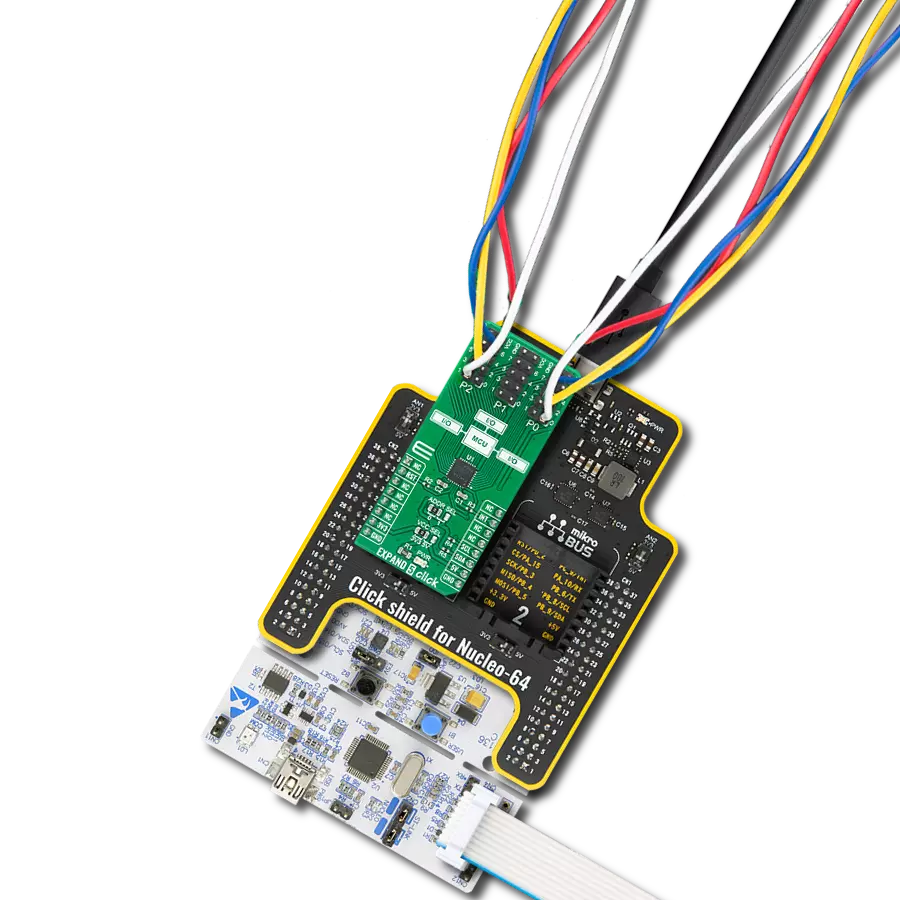
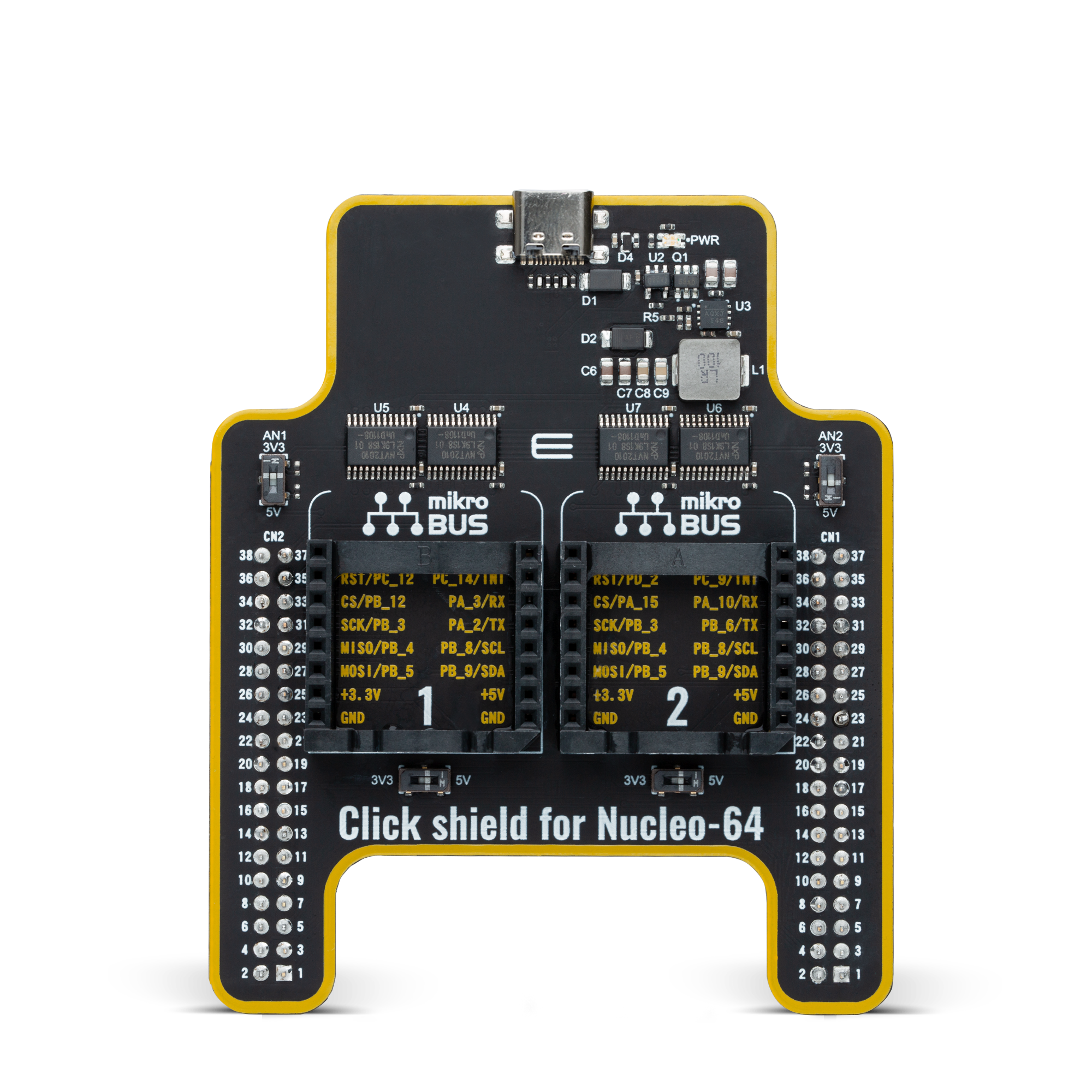
Click Shield for Nucleo-64 comes equipped with two proprietary mikroBUS™ sockets, allowing all the Click board™ devices to be interfaced with the STM32 Nucleo-64 board with no effort. This way, Mikroe allows its users to add any functionality from our ever-growing range of Click boards™, such as WiFi, GSM, GPS, Bluetooth, ZigBee, environmental sensors, LEDs, speech recognition, motor control, movement sensors, and many more. More than 1537 Click boards™, which can be stacked and integrated, are at your disposal. The STM32 Nucleo-64 boards are based on the microcontrollers in 64-pin packages, a 32-bit MCU with an ARM Cortex M4 processor operating at 84MHz, 512Kb Flash, and 96KB SRAM, divided into two regions where the top section represents the ST-Link/V2 debugger and programmer while the bottom section of the board is an actual development board. These boards are controlled and powered conveniently through a USB connection to program and efficiently debug the Nucleo-64 board out of the box, with an additional USB cable connected to the USB mini port on the board. Most of the STM32 microcontroller pins are brought to the IO pins on the left and right edge of the board, which are then connected to two existing mikroBUS™ sockets. This Click Shield also has several switches that perform functions such as selecting the logic levels of analog signals on mikroBUS™ sockets and selecting logic voltage levels of the mikroBUS™ sockets themselves. Besides, the user is offered the possibility of using any Click board™ with the help of existing bidirectional level-shifting voltage translators, regardless of whether the Click board™ operates at a 3.3V or 5V logic voltage level. Once you connect the STM32 Nucleo-64 board with our Click Shield for Nucleo-64, you can access hundreds of Click boards™, working with 3.3V or 5V logic voltage levels.
Used MCU Pins
mikroBUS™ mapper
Take a closer look
Click board™ Schematic

Step by step
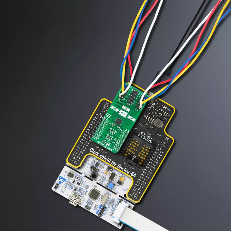
Project assembly
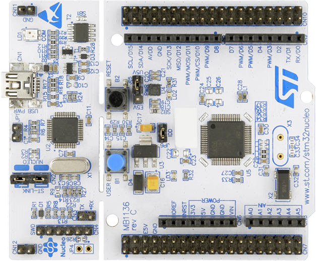
Start by selecting your development board and Click board™. Begin with the Nucleo 64 with STM32F334R8 MCU as your development board.


Track your results in real time
Application Output
1. Application Output - In Debug mode, the 'Application Output' window enables real-time data monitoring, offering direct insight into execution results. Ensure proper data display by configuring the environment correctly using the provided tutorial.

2. UART Terminal - Use the UART Terminal to monitor data transmission via a USB to UART converter, allowing direct communication between the Click board™ and your development system. Configure the baud rate and other serial settings according to your project's requirements to ensure proper functionality. For step-by-step setup instructions, refer to the provided tutorial.

3. Plot Output - The Plot feature offers a powerful way to visualize real-time sensor data, enabling trend analysis, debugging, and comparison of multiple data points. To set it up correctly, follow the provided tutorial, which includes a step-by-step example of using the Plot feature to display Click board™ readings. To use the Plot feature in your code, use the function: plot(*insert_graph_name*, variable_name);. This is a general format, and it is up to the user to replace 'insert_graph_name' with the actual graph name and 'variable_name' with the parameter to be displayed.

Software Support
Library Description
This library contains API for EXPAND 5 Click driver.
Key functions:
expand5_write_all_banks- Set all OUTPUT pins' logic levels in all banks functionexpand5_get_bank_pol- Get all pin polarity ( normal/inverted ) settings from one bank functionexpand5_get_pin_dir- Get a single pin's direction ( I/O ) setting function
Open Source
Code example
The complete application code and a ready-to-use project are available through the NECTO Studio Package Manager for direct installation in the NECTO Studio. The application code can also be found on the MIKROE GitHub account.
/*!
 * \file
 * \brief Expand5 Click example
 *
 * # Description
 * This example demonstrates the use of Expand 5 Click board.
 *
 * The demo application is composed of two sections :
 *
 * ## Application Init
 * Initalizes I2C driver, resets the device, configures all pins as output and makes an initial log.
 *
 * ## Application Task
 * This example shows the capabilities of the EXPAND 5 Click by toggling each of the 24 available pins.
 *
 * \author MikroE Team
 *
 */
// ------------------------------------------------------------------- INCLUDES

#include "board.h"
#include "log.h"
#include "expand5.h"

// ------------------------------------------------------------------ VARIABLES

static expand5_t expand5;
static log_t logger;

uint8_t pin_num;
uint8_t bank_out = 0x00;
uint8_t bank_low = 0x00;
char log_txt[ 50 ];

// ------------------------------------------------------ APPLICATION FUNCTIONS

void application_init ( void )
{
    log_cfg_t log_cfg;
    expand5_cfg_t cfg;

    /**
     * Logger initialization.
     * Default baud rate: 115200
     * Default log level: LOG_LEVEL_DEBUG
     * @note If USB_UART_RX and USB_UART_TX
     * are defined as HAL_PIN_NC, you will
     * need to define them manually for log to work.
     * See @b LOG_MAP_USB_UART macro definition for detailed explanation.
     */
    LOG_MAP_USB_UART( log_cfg );
    log_init( &logger, &log_cfg );
    log_info( &logger, "---- Application Init ----" );

    //  Click initialization.

    expand5_cfg_setup( &cfg );
    EXPAND5_MAP_MIKROBUS( cfg, MIKROBUS_1 );
    expand5_init( &expand5, &cfg );

    Delay_ms ( 100 );

    log_printf( &logger, "------------------- \r\n" );
    log_printf( &logger, "   EXPAND 5 Click   \r\n" );
    log_printf( &logger, "------------------- \r\n" );
    expand5_reset( &expand5 );
    expand5_set_all_dir( &expand5, bank_out, bank_out, bank_out );
    Delay_ms ( 100 );
    log_printf( &logger, "  Pins configured   \r\n" );
    log_printf( &logger, "     as output      \r\n" );
    log_printf( &logger, "------------------- \r\n" );
}

void application_task ( void )
{
    for ( pin_num = EXPAND5_P00; pin_num <= EXPAND5_P27; pin_num++ )
    {
        expand5_write_all_banks ( &expand5, bank_low, bank_low, bank_low );
        expand5_write_pin ( &expand5, pin_num, EXPAND5_HIGH );
        log_printf( &logger, "Pin %u is high \r\n", ( uint16_t ) pin_num );

        Delay_ms ( 200 );
        expand5_write_all_banks ( &expand5, bank_low, bank_low, bank_low );
    }
    log_printf( &logger, "------------------- \r\n" );
    Delay_ms ( 1000 );
}

int main ( void )
{
    /* Do not remove this line or clock might not be set correctly. */
    #ifdef PREINIT_SUPPORTED
    preinit();
    #endif

    application_init( );

    for ( ; ; )
    {
        application_task( );
    }

    return 0;
}

// ------------------------------------------------------------------------ END


