Manage fan speeds with MAX6615 and STM32F091RC for a better tomorrow
Where comfort meets control

Published Feb 26, 2024
Click board™
Fan 8 Click
Dev. board
Nucleo-64 with STM32F091RC MCU
Compiler
NECTO Studio
MCU
STM32F091RC
Enhance workplace productivity with our fan speed management solution, maintaining a comfortable and conducive environment for everyone
A
A
Hardware Overview
How does it work?
Fan 8 Click is based on the MAX6615, a compliant fan controller, and accurately two temperature-channels monitors from Analog Devices. The MAX6615 monitors either the internal die temperature or the temperature of external thermistors connected on the onboard headers labeled as TH and reports temperature values in digital form using a 2-wire serial interface. To adjust the speed of the cooling fans, the temperature data controls the duty cycle of a PWM output signal, which minimizes noise when the system is running cool but provides maximum cooling when power dissipation increases. Fan 8 Click communicates with MCU using the standard I2C 2-Wire interface to read data and configure settings with a maximum frequency of 400kHz. Besides, it also allows the choice of the least significant bit of its I2C slave address by
positioning the SMD jumpers labeled ADDR SEL to an appropriate position marked as 0 and 1. This way, the MAX6616 provides the opportunity of the nine possible different I2C addresses by positioning the SMD jumper to an appropriate position. The MAX6615 monitors the fans’ tachometer signals to detect fan failure. When the fan tachometer count is larger than the fan tachometer limit, the fan is considered failing. If that happens, the FAN_FAIL output represented by the FF pin, routed on the PWM pin of the mikroBUS™ socket, is asserted. Also, the MAX6615 features an over-temperature indicator routed on the AN pin of the mikroBUS™ socket, which sets high when a thermal fault occurs and can be used as a warning flag to initiate the system shutdown or to throttle clock frequency. In case of any irregularities, the MCU will also receive information
from an FLT pin (fault indicator), routed on the INT pin of the mikroBUS™ socket, in case further necessary configurations are necessary for proper operation. The Fan 8 Click supports an external fan power supply, connected to the input terminal labeled as VFAN with the value of 5V or 12V, while the fan connection wires can be connected to the onboard headers labeled as FAN1 and FAN2. This Click board™ can operate with both 3.3V and 5V logic voltage levels selected via the VCC SEL jumper. This way, it is allowed for both 3.3V and 5V capable MCUs to use the I2C communication lines properly. However, the Click board™ comes equipped with a library containing easy-to-use functions and an example code that can be used, as a reference, for further development.

Features overview
Development board
Nucleo-64 with STM32F091RC MCU offers a cost-effective and adaptable platform for developers to explore new ideas and prototype their designs. This board harnesses the versatility of the STM32 microcontroller, enabling users to select the optimal balance of performance and power consumption for their projects. It accommodates the STM32 microcontroller in the LQFP64 package and includes essential components such as a user LED, which doubles as an ARDUINO® signal, alongside user and reset push-buttons, and a 32.768kHz crystal oscillator for precise timing operations. Designed with expansion and flexibility in mind, the Nucleo-64 board features an ARDUINO® Uno V3 expansion connector and ST morpho extension pin
headers, granting complete access to the STM32's I/Os for comprehensive project integration. Power supply options are adaptable, supporting ST-LINK USB VBUS or external power sources, ensuring adaptability in various development environments. The board also has an on-board ST-LINK debugger/programmer with USB re-enumeration capability, simplifying the programming and debugging process. Moreover, the board is designed to simplify advanced development with its external SMPS for efficient Vcore logic supply, support for USB Device full speed or USB SNK/UFP full speed, and built-in cryptographic features, enhancing both the power efficiency and security of projects. Additional connectivity is
provided through dedicated connectors for external SMPS experimentation, a USB connector for the ST-LINK, and a MIPI® debug connector, expanding the possibilities for hardware interfacing and experimentation. Developers will find extensive support through comprehensive free software libraries and examples, courtesy of the STM32Cube MCU Package. This, combined with compatibility with a wide array of Integrated Development Environments (IDEs), including IAR Embedded Workbench®, MDK-ARM, and STM32CubeIDE, ensures a smooth and efficient development experience, allowing users to fully leverage the capabilities of the Nucleo-64 board in their projects.

Microcontroller Overview
MCU Card / MCU

Architecture
ARM Cortex-M0
MCU Memory (KB)
256
Silicon Vendor
STMicroelectronics
Pin count
64
RAM (Bytes)
32768
You complete me!
Accessories
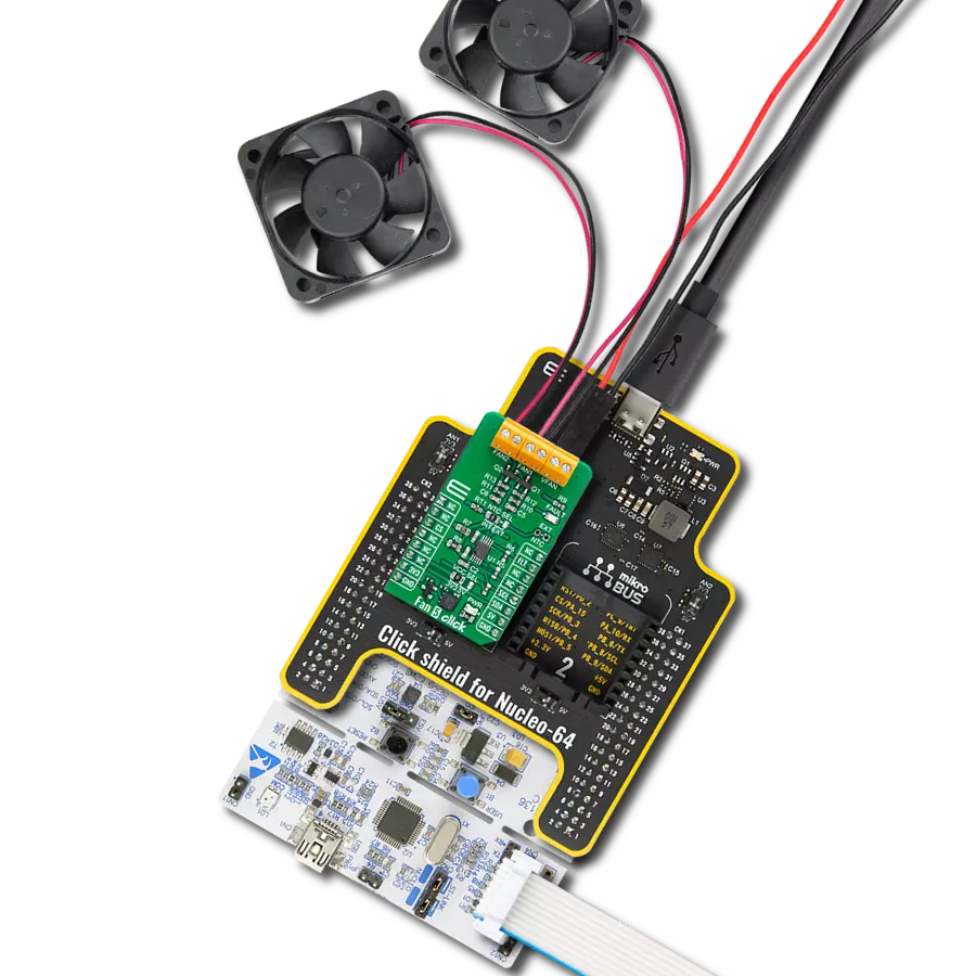
Click Shield for Nucleo-64 comes equipped with two proprietary mikroBUS™ sockets, allowing all the Click board™ devices to be interfaced with the STM32 Nucleo-64 board with no effort. This way, Mikroe allows its users to add any functionality from our ever-growing range of Click boards™, such as WiFi, GSM, GPS, Bluetooth, ZigBee, environmental sensors, LEDs, speech recognition, motor control, movement sensors, and many more. More than 1537 Click boards™, which can be stacked and integrated, are at your disposal. The STM32 Nucleo-64 boards are based on the microcontrollers in 64-pin packages, a 32-bit MCU with an ARM Cortex M4 processor operating at 84MHz, 512Kb Flash, and 96KB SRAM, divided into two regions where the top section represents the ST-Link/V2 debugger and programmer while the bottom section of the board is an actual development board. These boards are controlled and powered conveniently through a USB connection to program and efficiently debug the Nucleo-64 board out of the box, with an additional USB cable connected to the USB mini port on the board. Most of the STM32 microcontroller pins are brought to the IO pins on the left and right edge of the board, which are then connected to two existing mikroBUS™ sockets. This Click Shield also has several switches that perform functions such as selecting the logic levels of analog signals on mikroBUS™ sockets and selecting logic voltage levels of the mikroBUS™ sockets themselves. Besides, the user is offered the possibility of using any Click board™ with the help of existing bidirectional level-shifting voltage translators, regardless of whether the Click board™ operates at a 3.3V or 5V logic voltage level. Once you connect the STM32 Nucleo-64 board with our Click Shield for Nucleo-64, you can access hundreds of Click boards™, working with 3.3V or 5V logic voltage levels.

Used MCU Pins
mikroBUS™ mapper
Take a closer look
Click board™ Schematic

Step by step
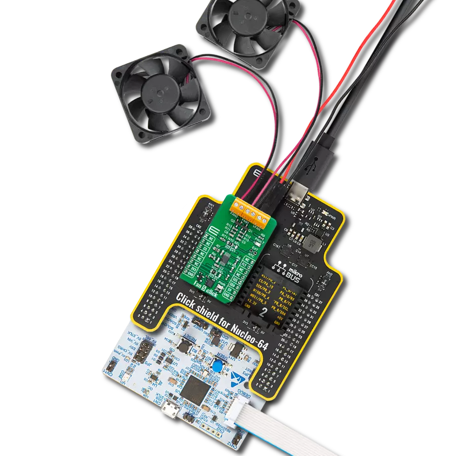
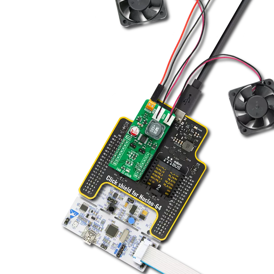
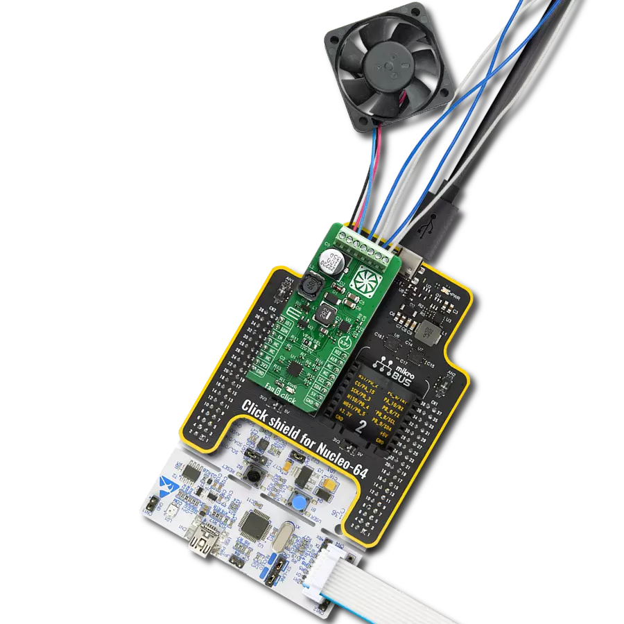
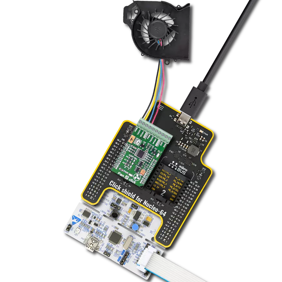
Project assembly
Start by selecting your development board and Click board™. Begin with the Nucleo-64 with STM32F091RC MCU as your development board.


Track your results in real time
Application Output
1. Application Output - In Debug mode, the 'Application Output' window enables real-time data monitoring, offering direct insight into execution results. Ensure proper data display by configuring the environment correctly using the provided tutorial.

2. UART Terminal - Use the UART Terminal to monitor data transmission via a USB to UART converter, allowing direct communication between the Click board™ and your development system. Configure the baud rate and other serial settings according to your project's requirements to ensure proper functionality. For step-by-step setup instructions, refer to the provided tutorial.

3. Plot Output - The Plot feature offers a powerful way to visualize real-time sensor data, enabling trend analysis, debugging, and comparison of multiple data points. To set it up correctly, follow the provided tutorial, which includes a step-by-step example of using the Plot feature to display Click board™ readings. To use the Plot feature in your code, use the function: plot(*insert_graph_name*, variable_name);. This is a general format, and it is up to the user to replace 'insert_graph_name' with the actual graph name and 'variable_name' with the parameter to be displayed.

Software Support
Library Description
This library contains API for Fan 8 Click driver.
Key functions:
fan8_set_duty_cycle- This function sets the duty cycle of the selected fan channel and waits until the duty cycle is set at the PWM outputfan8_measure_rpm- This function measures the RPM of the selected fan channelfan8_read_temperature- This function reads the temperature from the thermistor attached to the selected temperature channel
Open Source
Code example
The complete application code and a ready-to-use project are available through the NECTO Studio Package Manager for direct installation in the NECTO Studio. The application code can also be found on the MIKROE GitHub account.
/*!
 * @file main.c
 * @brief FAN8 Click example
 *
 * # Description
 * This example demonstrates the use of FAN 8 Click board.
 *
 * The demo application is composed of two sections :
 *
 * ## Application Init
 * Initializes the driver and performs the Click default configuration.
 *
 * ## Application Task
 * Changes the speed of fans at both channels by changing the PWM duty cycle, then calculates
 * the fans RPM from measured tachometer signal. It also reads the temperature of two thermistors.
 * The results are being displayed via USB UART where you can track their changes.
 *
 * @note
 * The MAX6615 measures the tachometer signal every 67s, therefore
 * the fan RPM value will be updated once per 67s.
 * An NTC 10K3 thermistor is required for proper temperature measurements.
 *
 * @author Stefan Filipovic
 *
 */

#include "board.h"
#include "log.h"
#include "fan8.h"

static fan8_t fan8;
static log_t logger;

void application_init ( void )
{
    log_cfg_t log_cfg;    /**< Logger config object. */
    fan8_cfg_t fan8_cfg;  /**< Click config object. */

    /**
     * Logger initialization.
     * Default baud rate: 115200
     * Default log level: LOG_LEVEL_DEBUG
     * @note If USB_UART_RX and USB_UART_TX
     * are defined as HAL_PIN_NC, you will
     * need to define them manually for log to work.
     * See @b LOG_MAP_USB_UART macro definition for detailed explanation.
     */
    LOG_MAP_USB_UART( log_cfg );
    log_init( &logger, &log_cfg );
    log_info( &logger, " Application Init " );

    // Click initialization.
    fan8_cfg_setup( &fan8_cfg );
    FAN8_MAP_MIKROBUS( fan8_cfg, MIKROBUS_1 );
    err_t init_flag = fan8_init( &fan8, &fan8_cfg );
    if ( I2C_MASTER_ERROR == init_flag )
    {
        log_error( &logger, " Application Init Error. " );
        log_info( &logger, " Please, run program again... " );

        for ( ; ; );
    }

    init_flag = fan8_default_cfg ( &fan8 );
    if ( FAN8_ERROR == init_flag )
    {
        log_error( &logger, " Default Config Error. " );
        log_info( &logger, " Please, run program again... " );

        for ( ; ; );
    }

    log_info( &logger, " Application Task " );
}

void application_task ( void )
{
    static uint8_t duty_cnt = FAN8_MIN_DUTY_CYCLE;
    static int8_t duty_inc = FAN8_DUTY_CYCLE_STEP_10;
    uint16_t fan_rpm = 0;
    float temperature = 0;

    if ( duty_cnt == FAN8_MAX_DUTY_CYCLE )
    {
        duty_inc = -FAN8_DUTY_CYCLE_STEP_10;
    }
    else if ( duty_cnt == ( FAN8_MIN_DUTY_CYCLE + FAN8_DUTY_CYCLE_STEP_10 ) )
    {
        duty_inc = FAN8_DUTY_CYCLE_STEP_10;
    }
    duty_cnt += duty_inc;

    log_printf( &logger, " - Channel 1 values -\r\n" );
    fan8_set_duty_cycle ( &fan8, FAN8_FAN_CHANNEL_1, duty_cnt );
    log_printf( &logger, " PWM Duty Cycle : %d\r\n", ( uint16_t ) duty_cnt );
    fan8_measure_rpm ( &fan8, FAN8_FAN_CHANNEL_1, FAN8_2_PULSES_PER_REVOLUTION, &fan_rpm );
    log_printf( &logger, " Last measured fan RPM : %u\r\n", fan_rpm );
    fan8_read_temperature ( &fan8, FAN8_TEMP_CHANNEL_1, &temperature );
    log_printf( &logger, " Temperature : %.2f C\r\n\r\n", temperature );

    log_printf( &logger, " - Channel 2 values -\r\n" );
    fan8_set_duty_cycle ( &fan8, FAN8_FAN_CHANNEL_2, duty_cnt );
    log_printf( &logger, " PWM Duty Cycle : %d\r\n", ( uint16_t ) duty_cnt );
    fan8_measure_rpm ( &fan8, FAN8_FAN_CHANNEL_2, FAN8_2_PULSES_PER_REVOLUTION, &fan_rpm );
    log_printf( &logger, " Last measured fan RPM : %u\r\n", fan_rpm );
    fan8_read_temperature ( &fan8, FAN8_TEMP_CHANNEL_2, &temperature );
    log_printf( &logger, " Temperature : %.2f C\r\n\r\n", temperature );

    if ( !fan8_check_fault_indicator ( &fan8 ) )
    {
        log_printf( &logger, " Fault detected!\r\n\r\n", temperature );
    }

    Delay_ms ( 500 );
}

int main ( void )
{
    /* Do not remove this line or clock might not be set correctly. */
    #ifdef PREINIT_SUPPORTED
    preinit();
    #endif

    application_init( );

    for ( ; ; )
    {
        application_task( );
    }

    return 0;
}

// ------------------------------------------------------------------------ END