Develop fast and accurate asset-tracking solution with MIA-M10Q and STM32F091RC
Ultra-low-power GNSS receiver for high-performance positioning capabilities
Published Feb 26, 2024
Click board™
GNSS 14 Click
Dev. board
Nucleo-64 with STM32F091RC MCU
Compiler
NECTO Studio
MCU
STM32F091RC
Enhance asset tracking with a professional-grade GNSS receiver, featuring exceptional sensitivity and rapid signal acquisition for optimal position availability, even in challenging environments
A
A
Hardware Overview
How does it work?
GNSS 14 Click is based on the MIA-M10Q, a standard precision GNSS module from u-blox. Super-S (Super-Signal) technology offers great RF sensitivity and can improve the dynamic position accuracy with small antennas or in non-line-of-sight scenarios. It possesses the SMA antenna connector with an impedance of 50Ω, which can connect the appropriate GNSS antenna that MIKROE offers, like GPS&GLONASS Passive Antenna, for improved range and received signal strength. u-blox receiver includes a time pulse function that provides pulses with a configurable pulse period, pulse length, and polarity (rising or falling edge). It also features a backup voltage
supply option. You can attach a battery to the GNSS 14 Click over the BAT connector. GNSS 14 Click uses a standard 2-wire UART interface to communicate with the host MCU with commonly used UART RX and TX pins and a baud rate from 4800 up to 921600bps. You can also use an I2C interface for the same purpose, but only in slave mode with a maximum bit rate of 400kbps. In both cases, the UBX and NMEA protocols are supported. The timepulse signal is available over the TP pin. The external interrupt signal over the EIT can be used for time mark feature, time aiding, and wake-up from power save modes. The RST pin allows you to reset the GNSS module with a Low
logic state. In addition to these pins, this Click board™ also has one digital I/O pin marked IO6, with the possibility of defining the purpose of this pin depending on the user's needs. It is only necessary to emphasize that when assigning a different function to an I/O, ensure that the default function is disabled where applicable. This Click board™ can be operated only with a 3.3V logic voltage level. The board must perform appropriate logic voltage level conversion before using MCUs with different logic levels. Also, it comes equipped with a library containing functions and an example code that can be used as a reference for further development.

Features overview
Development board
Nucleo-64 with STM32F091RC MCU offers a cost-effective and adaptable platform for developers to explore new ideas and prototype their designs. This board harnesses the versatility of the STM32 microcontroller, enabling users to select the optimal balance of performance and power consumption for their projects. It accommodates the STM32 microcontroller in the LQFP64 package and includes essential components such as a user LED, which doubles as an ARDUINO® signal, alongside user and reset push-buttons, and a 32.768kHz crystal oscillator for precise timing operations. Designed with expansion and flexibility in mind, the Nucleo-64 board features an ARDUINO® Uno V3 expansion connector and ST morpho extension pin
headers, granting complete access to the STM32's I/Os for comprehensive project integration. Power supply options are adaptable, supporting ST-LINK USB VBUS or external power sources, ensuring adaptability in various development environments. The board also has an on-board ST-LINK debugger/programmer with USB re-enumeration capability, simplifying the programming and debugging process. Moreover, the board is designed to simplify advanced development with its external SMPS for efficient Vcore logic supply, support for USB Device full speed or USB SNK/UFP full speed, and built-in cryptographic features, enhancing both the power efficiency and security of projects. Additional connectivity is
provided through dedicated connectors for external SMPS experimentation, a USB connector for the ST-LINK, and a MIPI® debug connector, expanding the possibilities for hardware interfacing and experimentation. Developers will find extensive support through comprehensive free software libraries and examples, courtesy of the STM32Cube MCU Package. This, combined with compatibility with a wide array of Integrated Development Environments (IDEs), including IAR Embedded Workbench®, MDK-ARM, and STM32CubeIDE, ensures a smooth and efficient development experience, allowing users to fully leverage the capabilities of the Nucleo-64 board in their projects.

Microcontroller Overview
MCU Card / MCU

Architecture
ARM Cortex-M0
MCU Memory (KB)
256
Silicon Vendor
STMicroelectronics
Pin count
64
RAM (Bytes)
32768
You complete me!
Accessories
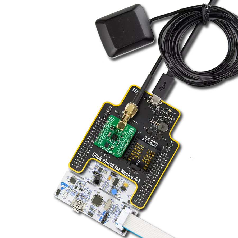
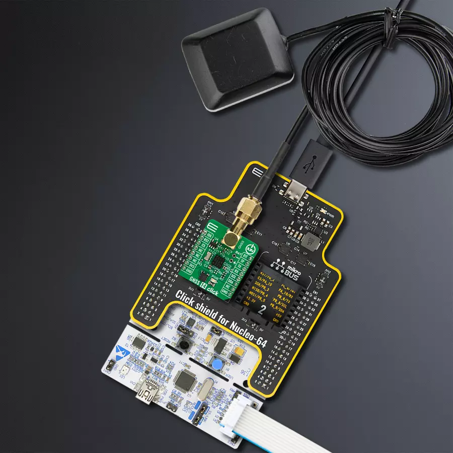
Click Shield for Nucleo-64 comes equipped with two proprietary mikroBUS™ sockets, allowing all the Click board™ devices to be interfaced with the STM32 Nucleo-64 board with no effort. This way, Mikroe allows its users to add any functionality from our ever-growing range of Click boards™, such as WiFi, GSM, GPS, Bluetooth, ZigBee, environmental sensors, LEDs, speech recognition, motor control, movement sensors, and many more. More than 1537 Click boards™, which can be stacked and integrated, are at your disposal. The STM32 Nucleo-64 boards are based on the microcontrollers in 64-pin packages, a 32-bit MCU with an ARM Cortex M4 processor operating at 84MHz, 512Kb Flash, and 96KB SRAM, divided into two regions where the top section represents the ST-Link/V2 debugger and programmer while the bottom section of the board is an actual development board. These boards are controlled and powered conveniently through a USB connection to program and efficiently debug the Nucleo-64 board out of the box, with an additional USB cable connected to the USB mini port on the board. Most of the STM32 microcontroller pins are brought to the IO pins on the left and right edge of the board, which are then connected to two existing mikroBUS™ sockets. This Click Shield also has several switches that perform functions such as selecting the logic levels of analog signals on mikroBUS™ sockets and selecting logic voltage levels of the mikroBUS™ sockets themselves. Besides, the user is offered the possibility of using any Click board™ with the help of existing bidirectional level-shifting voltage translators, regardless of whether the Click board™ operates at a 3.3V or 5V logic voltage level. Once you connect the STM32 Nucleo-64 board with our Click Shield for Nucleo-64, you can access hundreds of Click boards™, working with 3.3V or 5V logic voltage levels.

Active GPS antenna is designed to enhance the performance of your GPS and GNSS Click boards™. This external antenna boasts a robust construction, making it ideal for various weather conditions. With a frequency range of 1575.42MHz and a 50Ohm impedance, it ensures reliable signal reception. The antenna delivers a gain of greater than -4dBic within a wide angular range, securing over 75% coverage. The bandwidth of +/- 5MHz further guarantees precise data acquisition. Featuring a Right-Hand Circular Polarization (RHCP), this antenna offers stable signal reception. Its compact dimensions of 48.53915mm and a 2-meter cable make it easy to install. The magnetic antenna type with an SMA male connector ensures a secure and convenient connection. If you require a dependable external antenna for your locator device, our active GPS antenna is the perfect solution.

Used MCU Pins
mikroBUS™ mapper
Take a closer look
Click board™ Schematic

Step by step
Project assembly
Start by selecting your development board and Click board™. Begin with the Nucleo-64 with STM32F091RC MCU as your development board.


Software Support
Library Description
This library contains API for GNSS 14 Click driver.
Key functions:
gnss14_parse_gngga- This function parses the GNGGA data from the read response buffergnss14_reset_device- This function resets the device by toggling the RST pin
Open Source
Code example
The complete application code and a ready-to-use project are available through the NECTO Studio Package Manager for direct installation in the NECTO Studio. The application code can also be found on the MIKROE GitHub account.
/*!
 * @file main.c
 * @brief GNSS 14 Click Example.
 *
 * # Description
 * This example demonstrates the use of GNSS 14 Click board by reading and displaying
 * the GNSS coordinates.
 *
 * The demo application is composed of two sections :
 *
 * ## Application Init
 * Initializes the driver and resets the Click board.
 *
 * ## Application Task
 * Reads the received data, parses the GNGGA info from it, and once it receives the position fix
 * it will start displaying the coordinates on the USB UART.
 *
 * ## Additional Function
 * - static void gnss14_clear_app_buf ( void )
 * - static err_t gnss14_process ( gnss14_t *ctx )
 * - static void gnss14_parser_application ( char *rsp )
 *
 * @author Nenad Filipovic
 *
 */

#include "board.h"
#include "log.h"
#include "gnss14.h"

// Application buffer size
#define APP_BUFFER_SIZE             500
#define PROCESS_BUFFER_SIZE         200

static gnss14_t gnss14;
static log_t logger;

static uint8_t app_buf[ APP_BUFFER_SIZE ] = { 0 };
static int32_t app_buf_len = 0;

/**
 * @brief GNSS 14 clearing application buffer.
 * @details This function clears memory of application buffer and reset its length.
 * @note None.
 */
static void gnss14_clear_app_buf ( void );

/**
 * @brief GNSS 14 data reading function.
 * @details This function reads data from device and concatenates data to application buffer.
 * @param[in] ctx : Click context object.
 * See #gnss14_t object definition for detailed explanation.
 * @return @li @c  0 - Read some data.
 *         @li @c -1 - Nothing is read.
 * See #err_t definition for detailed explanation.
 * @note None.
 */
static err_t gnss14_process ( gnss14_t *ctx );

/**
 * @brief GNSS 14 parser application.
 * @param[in] rsp Response buffer.
 * @details This function logs GNSS data on the USB UART.
 * @return None.
 * @note None.
 */
static void gnss14_parser_application ( char *rsp );

void application_init ( void )
{
    log_cfg_t log_cfg;  /**< Logger config object. */
    gnss14_cfg_t gnss14_cfg;  /**< Click config object. */

    /**
     * Logger initialization.
     * Default baud rate: 115200
     * Default log level: LOG_LEVEL_DEBUG
     * @note If USB_UART_RX and USB_UART_TX
     * are defined as HAL_PIN_NC, you will
     * need to define them manually for log to work.
     * See @b LOG_MAP_USB_UART macro definition for detailed explanation.
     */
    LOG_MAP_USB_UART( log_cfg );
    log_init( &logger, &log_cfg );
    log_info( &logger, " Application Init " );

    // Click initialization.
    gnss14_cfg_setup( &gnss14_cfg );
    GNSS14_MAP_MIKROBUS( gnss14_cfg, MIKROBUS_1 );
    if ( UART_ERROR == gnss14_init( &gnss14, &gnss14_cfg ) )
    {
        log_error( &logger, " Communication init." );
        for ( ; ; );
    }

    gnss14_reset_device( &gnss14 );
    log_info( &logger, " Application Task " );
}

void application_task ( void )
{
    if ( GNSS14_OK == gnss14_process( &gnss14 ) )
    {
        if ( app_buf_len > ( sizeof ( GNSS14_RSP_GNGGA ) + GNSS14_GNGGA_ELEMENT_SIZE ) )
        {
            gnss14_parser_application( app_buf );
        }
    }
}

int main ( void )
{
    /* Do not remove this line or clock might not be set correctly. */
    #ifdef PREINIT_SUPPORTED
    preinit();
    #endif

    application_init( );

    for ( ; ; )
    {
        application_task( );
    }

    return 0;
}

static void gnss14_clear_app_buf ( void )
{
    memset( app_buf, 0, app_buf_len );
    app_buf_len = 0;
}

static err_t gnss14_process ( gnss14_t *ctx )
{
    int32_t rx_size = 0;
    char rx_buf[ PROCESS_BUFFER_SIZE ] = { 0 };
    if ( GNSS14_DRV_SEL_UART == ctx->drv_sel )
    {
        rx_size = gnss14_generic_read( ctx, rx_buf, PROCESS_BUFFER_SIZE );
    }
    else if ( ( GNSS14_DRV_SEL_I2C == ctx->drv_sel ) )
    {
        if ( GNSS14_OK == gnss14_generic_read( ctx, rx_buf, 1 ) )
        {
            if ( GNSS14_DUMMY != rx_buf[ 0 ] )
            {
                rx_size = 1;
            }
        }
    }
    if ( rx_size > 0 )
    {
        int32_t buf_cnt = 0;
        if ( ( app_buf_len + rx_size ) > PROCESS_BUFFER_SIZE )
        {
            gnss14_clear_app_buf(  );
            return GNSS14_ERROR;
        }
        else
        {
            buf_cnt = app_buf_len;
            app_buf_len += rx_size;
        }
        for ( int32_t rx_cnt = 0; rx_cnt < rx_size; rx_cnt++ )
        {
            if ( rx_buf[ rx_cnt ] )
            {
                app_buf[ ( buf_cnt + rx_cnt ) ] = rx_buf[ rx_cnt ];
            }
            else
            {
                app_buf_len--;
                buf_cnt--;
            }
        }
        return GNSS14_OK;
    }
    return GNSS14_ERROR;
}

static void gnss14_parser_application ( char *rsp )
{
    char element_buf[ 100 ] = { 0 };
    if ( GNSS14_OK == gnss14_parse_gngga( rsp, GNSS14_GNGGA_LATITUDE, element_buf ) )
    {
        static uint8_t wait_for_fix_cnt = 0;
        if ( strlen( element_buf ) > 0 )
        {
            log_printf( &logger, "\r\n Latitude: %.2s degrees, %s minutes \r\n", element_buf, &element_buf[ 2 ] );
            gnss14_parse_gngga( rsp, GNSS14_GNGGA_LONGITUDE, element_buf );
            log_printf( &logger, " Longitude: %.3s degrees, %s minutes \r\n", element_buf, &element_buf[ 3 ] );
            memset( element_buf, 0, sizeof( element_buf ) );
            gnss14_parse_gngga( rsp, GNSS14_GNGGA_ALTITUDE, element_buf );
            log_printf( &logger, " Altitude: %s m \r\n", element_buf );
            wait_for_fix_cnt = 0;
        }
        else
        {
            if ( wait_for_fix_cnt % 5 == 0 )
            {
                log_printf( &logger, " Waiting for the position fix...\r\n\n" );
                wait_for_fix_cnt = 0;
            }
            wait_for_fix_cnt++;
        }
        gnss14_clear_app_buf(  );
    }
}

// ------------------------------------------------------------------------ END
Additional Support
Resources
Category:GPS/GNSS


