Achieve versatile motion detection for diverse needs with EKMC1603111 and STM32F091RC
Infrared intelligence: Pyroelectric motion at your service!

Published Feb 26, 2024
Click board™
Motion 4 Click
Dev. board
Nucleo-64 with STM32F091RC MCU
Compiler
NECTO Studio
MCU
STM32F091RC
Our purpose is to empower homes and businesses with the unmatched convenience and efficiency of PIR motion sensors, creating smart and responsive environments that adapt seamlessly to the needs of occupants
A
A
Hardware Overview
How does it work?
Motion 4 Click is based on EKMC1603111, a PIR motion sensor from Panasonic used as a human motion detector. This PIR sensor can detect changes in the amount of infrared radiation impinging upon it, which varies depending on the temperature and surface characteristics of the objects in front of the sensor. Detection performance of EKMC1603111 at ambient temperature of 25°C with temperature difference higher than 4°C is up to 12m. Angle detection area with 92 detection zones is 102°(±51°)horizontal and 92°(±46°)vertical. Output from PIR sensor is feed into buffer and then photorelay alowing users to directly control with galvanic isolation from sensor and MCU electronic devices such as lights, motors, gates, and more. The TLP241A photorelay
is able to effectively replace traditionally used mechanical relays, bringing up the full set of inherited benefits: virtually unlimited number of cycles since there are no moving parts that would wear off, no bouncing effect on the output contacts, high resistance to mechanical shock and environmental influence, low current required for the activation, constant resistance since no carbon and rust can build up on contacts, there is no sparking or electric arc forming while operated, compact size, higher isolation voltage, and so on. When an object, such as a person, passes in front of the background, such as a wall, the temperature at that point in the sensor's field of view will rise from room temperature to body temperature, and then back again. The sensor converts the
resulting change in the incoming infrared radiation into a change in the output voltage, and this triggers the detection. Objects of similar temperature but different surface characteristics may also have a different infrared emission pattern, and thus moving them with respect to the background may trigger the detector as well. In some cases, going back and forth towards the sensor (parallel movement to the axis Z), may not be detected. Difficulty in sensing the heat source is that glass, acrylic or similar materials standing between the target and the sensor may not allow a correct transmission of infrared rays and also non-movement or quick movements of the heat source inside the detection area.


Features overview
Development board
Nucleo-64 with STM32F091RC MCU offers a cost-effective and adaptable platform for developers to explore new ideas and prototype their designs. This board harnesses the versatility of the STM32 microcontroller, enabling users to select the optimal balance of performance and power consumption for their projects. It accommodates the STM32 microcontroller in the LQFP64 package and includes essential components such as a user LED, which doubles as an ARDUINO® signal, alongside user and reset push-buttons, and a 32.768kHz crystal oscillator for precise timing operations. Designed with expansion and flexibility in mind, the Nucleo-64 board features an ARDUINO® Uno V3 expansion connector and ST morpho extension pin
headers, granting complete access to the STM32's I/Os for comprehensive project integration. Power supply options are adaptable, supporting ST-LINK USB VBUS or external power sources, ensuring adaptability in various development environments. The board also has an on-board ST-LINK debugger/programmer with USB re-enumeration capability, simplifying the programming and debugging process. Moreover, the board is designed to simplify advanced development with its external SMPS for efficient Vcore logic supply, support for USB Device full speed or USB SNK/UFP full speed, and built-in cryptographic features, enhancing both the power efficiency and security of projects. Additional connectivity is
provided through dedicated connectors for external SMPS experimentation, a USB connector for the ST-LINK, and a MIPI® debug connector, expanding the possibilities for hardware interfacing and experimentation. Developers will find extensive support through comprehensive free software libraries and examples, courtesy of the STM32Cube MCU Package. This, combined with compatibility with a wide array of Integrated Development Environments (IDEs), including IAR Embedded Workbench®, MDK-ARM, and STM32CubeIDE, ensures a smooth and efficient development experience, allowing users to fully leverage the capabilities of the Nucleo-64 board in their projects.

Microcontroller Overview
MCU Card / MCU

Architecture
ARM Cortex-M0
MCU Memory (KB)
256
Silicon Vendor
STMicroelectronics
Pin count
64
RAM (Bytes)
32768
You complete me!
Accessories
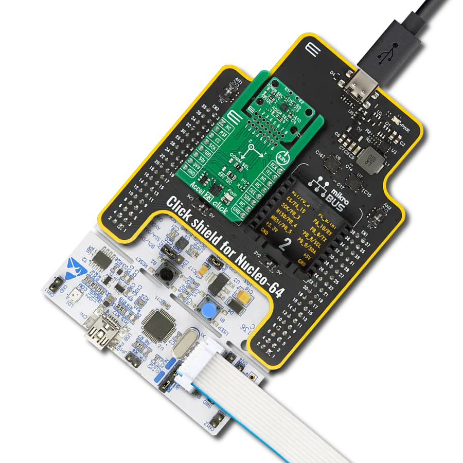
Click Shield for Nucleo-64 comes equipped with two proprietary mikroBUS™ sockets, allowing all the Click board™ devices to be interfaced with the STM32 Nucleo-64 board with no effort. This way, Mikroe allows its users to add any functionality from our ever-growing range of Click boards™, such as WiFi, GSM, GPS, Bluetooth, ZigBee, environmental sensors, LEDs, speech recognition, motor control, movement sensors, and many more. More than 1537 Click boards™, which can be stacked and integrated, are at your disposal. The STM32 Nucleo-64 boards are based on the microcontrollers in 64-pin packages, a 32-bit MCU with an ARM Cortex M4 processor operating at 84MHz, 512Kb Flash, and 96KB SRAM, divided into two regions where the top section represents the ST-Link/V2 debugger and programmer while the bottom section of the board is an actual development board. These boards are controlled and powered conveniently through a USB connection to program and efficiently debug the Nucleo-64 board out of the box, with an additional USB cable connected to the USB mini port on the board. Most of the STM32 microcontroller pins are brought to the IO pins on the left and right edge of the board, which are then connected to two existing mikroBUS™ sockets. This Click Shield also has several switches that perform functions such as selecting the logic levels of analog signals on mikroBUS™ sockets and selecting logic voltage levels of the mikroBUS™ sockets themselves. Besides, the user is offered the possibility of using any Click board™ with the help of existing bidirectional level-shifting voltage translators, regardless of whether the Click board™ operates at a 3.3V or 5V logic voltage level. Once you connect the STM32 Nucleo-64 board with our Click Shield for Nucleo-64, you can access hundreds of Click boards™, working with 3.3V or 5V logic voltage levels.

Used MCU Pins
mikroBUS™ mapper
Take a closer look
Click board™ Schematic

Step by step
Project assembly
Start by selecting your development board and Click board™. Begin with the Nucleo-64 with STM32F091RC MCU as your development board.


Track your results in real time
Application Output
1. Application Output - In Debug mode, the 'Application Output' window enables real-time data monitoring, offering direct insight into execution results. Ensure proper data display by configuring the environment correctly using the provided tutorial.

2. UART Terminal - Use the UART Terminal to monitor data transmission via a USB to UART converter, allowing direct communication between the Click board™ and your development system. Configure the baud rate and other serial settings according to your project's requirements to ensure proper functionality. For step-by-step setup instructions, refer to the provided tutorial.

3. Plot Output - The Plot feature offers a powerful way to visualize real-time sensor data, enabling trend analysis, debugging, and comparison of multiple data points. To set it up correctly, follow the provided tutorial, which includes a step-by-step example of using the Plot feature to display Click board™ readings. To use the Plot feature in your code, use the function: plot(*insert_graph_name*, variable_name);. This is a general format, and it is up to the user to replace 'insert_graph_name' with the actual graph name and 'variable_name' with the parameter to be displayed.

Software Support
Library Description
This library contains API for Motion 4 Click driver.
Key functions:
motion4_enable- This function enables/disables motion sensor by setting EN pin statemotion4_detect_state- This function returns INT pin state
Open Source
Code example
The complete application code and a ready-to-use project are available through the NECTO Studio Package Manager for direct installation in the NECTO Studio. The application code can also be found on the MIKROE GitHub account.
/*!
 * @file main.c
 * @brief Motion 4 Click Example.
 *
 * # Description
 * This example demonstrates the use of Motion 4 Click boards.
 *
 * The demo application is composed of two sections :
 *
 * ## Application Init
 * Initializes the driver and enables the motion sensor.
 *
 * ## Application Task
 * It checks if the sensor has detected movement and therefore displays
 * the desired message on the USB UART.
 *
 * @author Jelena Milosavljevic
 *
 */
// ------------------------------------------------------------------- INCLUDES
#include "board.h"
#include "log.h"
#include "motion4.h"

// ------------------------------------------------------------------ VARIABLES

static motion4_t motion4;   /**< Motion 4 Click driver object. */
static log_t logger;    /**< Logger object. */

motion4_detect_state_t motion_state;
motion4_detect_state_t motion_old_state;
// ------------------------------------------------------ APPLICATION FUNCTIONS

void application_init ( void ) {
    log_cfg_t log_cfg;  /**< Logger config object. */
    motion4_cfg_t motion4_cfg;  /**< Click config object. */

    /**
     * Logger initialization.
     * Default baud rate: 115200
     * Default log level: LOG_LEVEL_DEBUG
     * @note If USB_UART_RX and USB_UART_TX
     * are defined as HAL_PIN_NC, you will
     * need to define them manually for log to work.
     * See @b LOG_MAP_USB_UART macro definition for detailed explanation.
     */
    LOG_MAP_USB_UART( log_cfg );
    log_init( &logger, &log_cfg );
    log_info( &logger, " Application Init " );

    // Click initialization.

    motion4_cfg_setup( &motion4_cfg );
    MOTION4_MAP_MIKROBUS( motion4_cfg, MIKROBUS_1 );
    if ( motion4_init( &motion4, &motion4_cfg ) == DIGITAL_OUT_UNSUPPORTED_PIN ) {

        log_error( &logger, " Application Init Error. " );
        log_info( &logger, " Please, run program again... " );

        for ( ; ; );
    }

    motion4_enable( &motion4, MOTION4_MODULE_ENABLE );
    Delay_ms ( 100 );
    log_printf( &logger, "The sensor is ready.\r\n" );
    log_printf( &logger, "-----------------------\r\n" );
}

void application_task ( void ) {
    uint8_t int_status;

    int_status = motion4_detect_state( &motion4 );

    if ( int_status == MOTION4_DETECT_OBJECT ) {

        log_printf( &logger, "Motion detected!\r\n" );
        log_printf( &logger, "-----------------------\r\n" );
        while ( int_status == MOTION4_DETECT_OBJECT ) {

            int_status = motion4_detect_state( &motion4 );
        }
        log_printf( &logger, "The sensor is ready.\r\n" );
        log_printf( &logger, "-----------------------\r\n" );
        Delay_ms ( 100 );
    }
}


int main ( void )
{
    /* Do not remove this line or clock might not be set correctly. */
    #ifdef PREINIT_SUPPORTED
    preinit();
    #endif

    application_init( );

    for ( ; ; )
    {
        application_task( );
    }

    return 0;
}

// ------------------------------------------------------------------------ END
Additional Support
Resources
Category:Motion