Thrive in weather forecasting and atmospheric pressure measurement with MS5837 and STM32F410RB
Feel the pulse of innovation: Where precision and pressure converge
Published Oct 08, 2024
Click board™
Pressure 7 Click
Dev. board
Nucleo 64 with STM32F410RB MCU
Compiler
NECTO Studio
MCU
STM32F410RB
Unleash the full potential of your projects with our digital pressure measurement solution, engineered to set new standards in reliability and performance
A
A
Hardware Overview
How does it work?
Pressure 7 Click is based on the MS5837, a pressure sensor from TE Connectivity. This is a highly integrated piezo-resistive absolute pressure sensor, based on the MEMS technology by TE Connectivity, which can measure the pressure in the range from 0 to 30 bar, and the temperature in the range from -20° to +85° C. The MEMS (micro electromechanical sensor) is placed in a hermetically sealed, anti-magnetic stainless-steel cap, protected with the special gel. This makes the sensor itself water-resistant. Besides the piezo-resistive sensor, the MS5837 module also contains the highly integrated ASIC (Application Specific Integrated Circuit) which contains all the necessary components that are required to convert the uncompensated voltage from the MEMS into 24-bit digital data. The MS5837 sensor offers the standard I2C interface for the communication with the host MCU, using only a few commands. The advanced ASIC which contains the 24bit delta-sigma analog-to-digital converter (ADC), provides a very high resolution of 0.2 mbar per step, as well as the fast conversion time, down to 0.5 ms. The already low power consumption can be further regulated by utilizing different output sample rates (OSR), within the
range from 256 to 8192. The OSR setting is contained within a single command, which is sent from the host MCU to initiate the conversion. The OSR directly affects both the current consumption of the MS5837 sensor, as well as the conversion time: the higher the OSR ratio, the more current is required, and less time to complete the conversion cycle. The user application should perform a reset of the MS5837 sensor module before reading the compensation parameters from the PROM. These compensation parameters should be stored by the application for the later use. When the MS5837 module receives the conversion command over the I2C interface, it will start the thermal and pressure conversion process. After the conversion, the data is clocked out when ADC Read command is received. After receiving the raw conversion data from the MS5837, the application should convert this data, applying the previously stored calibration parameters. The output data rate, as well as the specific conversion type (thermal or pressure conversion) depend on the received command. The MS5837 datasheet offers detailed explanation of the command byte. The conversion data is available over the I2C interface, as mentioned before. The I2C bus lines (SDA and SCL)
are routed to the respective I2C mikroBUS™ pins which are pulled up by resistors on the Click board™ itself, allowing the Click board™ to be used right out of the box. The datasheet of the MS5837 sensor module also offers conversion formulas and algorithms which can be used to convert the raw binary values from the respective PROM registers to physical, human-readable format. However, Pressure 7 click comes with the library that contains functions which output converted and properly formatted thermal and pressure readings. In addition to the MS5837 sensor module, Pressure 7 click incorporates an additional IC. It is the PCA9306, a well-known bi-directional I2C level translator from Texas Instruments, used on many different Click board™ designs, due to its simplicity and reliability. Since the MS5837 sensor is limited to 3.3V operation, this IC allows it to be used with the 5V logic level, expanding the connectivity of the Pressure 7 click to MCUs which use 5V levels for the I2C communication. The logic voltage level selection can be made by switching the small onboard SMD jumper labeled as VCC SEL, to a proper position (3V3 or 5V).


Features overview
Development board
Nucleo-64 with STM32F410RB MCU offers a cost-effective and adaptable platform for developers to explore new ideas and prototype their designs. This board harnesses the versatility of the STM32 microcontroller, enabling users to select the optimal balance of performance and power consumption for their projects. It accommodates the STM32 microcontroller in the LQFP64 package and includes essential components such as a user LED, which doubles as an ARDUINO® signal, alongside user and reset push-buttons, and a 32.768kHz crystal oscillator for precise timing operations. Designed with expansion and flexibility in mind, the Nucleo-64 board features an ARDUINO® Uno V3 expansion connector and ST morpho extension pin
headers, granting complete access to the STM32's I/Os for comprehensive project integration. Power supply options are adaptable, supporting ST-LINK USB VBUS or external power sources, ensuring adaptability in various development environments. The board also has an on-board ST-LINK debugger/programmer with USB re-enumeration capability, simplifying the programming and debugging process. Moreover, the board is designed to simplify advanced development with its external SMPS for efficient Vcore logic supply, support for USB Device full speed or USB SNK/UFP full speed, and built-in cryptographic features, enhancing both the power efficiency and security of projects. Additional connectivity is
provided through dedicated connectors for external SMPS experimentation, a USB connector for the ST-LINK, and a MIPI® debug connector, expanding the possibilities for hardware interfacing and experimentation. Developers will find extensive support through comprehensive free software libraries and examples, courtesy of the STM32Cube MCU Package. This, combined with compatibility with a wide array of Integrated Development Environments (IDEs), including IAR Embedded Workbench®, MDK-ARM, and STM32CubeIDE, ensures a smooth and efficient development experience, allowing users to fully leverage the capabilities of the Nucleo-64 board in their projects.

Microcontroller Overview
MCU Card / MCU

Architecture
ARM Cortex-M4
MCU Memory (KB)
128
Silicon Vendor
STMicroelectronics
Pin count
64
RAM (Bytes)
32768
You complete me!
Accessories
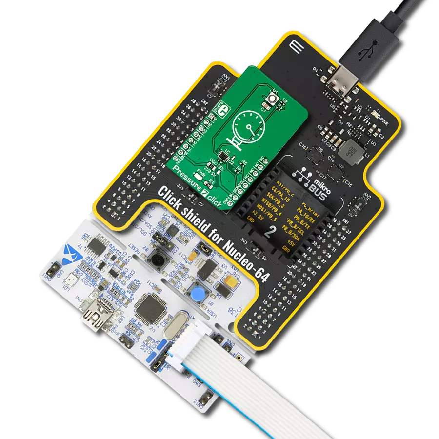
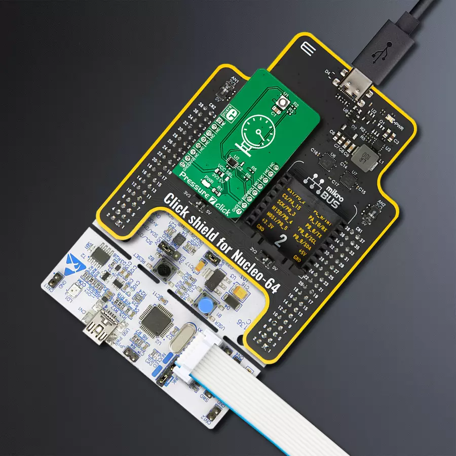
Click Shield for Nucleo-64 comes equipped with two proprietary mikroBUS™ sockets, allowing all the Click board™ devices to be interfaced with the STM32 Nucleo-64 board with no effort. This way, Mikroe allows its users to add any functionality from our ever-growing range of Click boards™, such as WiFi, GSM, GPS, Bluetooth, ZigBee, environmental sensors, LEDs, speech recognition, motor control, movement sensors, and many more. More than 1537 Click boards™, which can be stacked and integrated, are at your disposal. The STM32 Nucleo-64 boards are based on the microcontrollers in 64-pin packages, a 32-bit MCU with an ARM Cortex M4 processor operating at 84MHz, 512Kb Flash, and 96KB SRAM, divided into two regions where the top section represents the ST-Link/V2 debugger and programmer while the bottom section of the board is an actual development board. These boards are controlled and powered conveniently through a USB connection to program and efficiently debug the Nucleo-64 board out of the box, with an additional USB cable connected to the USB mini port on the board. Most of the STM32 microcontroller pins are brought to the IO pins on the left and right edge of the board, which are then connected to two existing mikroBUS™ sockets. This Click Shield also has several switches that perform functions such as selecting the logic levels of analog signals on mikroBUS™ sockets and selecting logic voltage levels of the mikroBUS™ sockets themselves. Besides, the user is offered the possibility of using any Click board™ with the help of existing bidirectional level-shifting voltage translators, regardless of whether the Click board™ operates at a 3.3V or 5V logic voltage level. Once you connect the STM32 Nucleo-64 board with our Click Shield for Nucleo-64, you can access hundreds of Click boards™, working with 3.3V or 5V logic voltage levels.

Used MCU Pins
mikroBUS™ mapper
Take a closer look
Click board™ Schematic

Step by step
Project assembly
Start by selecting your development board and Click board™. Begin with the Nucleo 64 with STM32F410RB MCU as your development board.


Track your results in real time
Application Output
1. Application Output - In Debug mode, the 'Application Output' window enables real-time data monitoring, offering direct insight into execution results. Ensure proper data display by configuring the environment correctly using the provided tutorial.

2. UART Terminal - Use the UART Terminal to monitor data transmission via a USB to UART converter, allowing direct communication between the Click board™ and your development system. Configure the baud rate and other serial settings according to your project's requirements to ensure proper functionality. For step-by-step setup instructions, refer to the provided tutorial.

3. Plot Output - The Plot feature offers a powerful way to visualize real-time sensor data, enabling trend analysis, debugging, and comparison of multiple data points. To set it up correctly, follow the provided tutorial, which includes a step-by-step example of using the Plot feature to display Click board™ readings. To use the Plot feature in your code, use the function: plot(*insert_graph_name*, variable_name);. This is a general format, and it is up to the user to replace 'insert_graph_name' with the actual graph name and 'variable_name' with the parameter to be displayed.

Software Support
Library Description
This library contains API for Pressure 7 Click driver.
Key functions:
pressure7_read_PROM- This function reads calibration data from PROMpressure7_start_measurement- This function starts measurement and calculation datapressure7_get_sensor_data- This function reads pressure and temperature data
Open Source
Code example
The complete application code and a ready-to-use project are available through the NECTO Studio Package Manager for direct installation in the NECTO Studio. The application code can also be found on the MIKROE GitHub account.
/*!
 * \file
 * \brief Pressure7 Click example
 *
 * # Description
 * This example reads sensor temperature and pressure output on every 3 seconds and
 * prints it on UART Terminal.
 *
 * The demo application is composed of two sections :
 *
 * ## Application Init
 * Initialize Logger and Click object and call pressure7_read_PROM() function.
 *
 * ## Application Task
 * Get sensor data on every 3 seconds and send measured temperature and pressure to logger.
 *
 *
 * \author MikroE Team
 *
 */
// ------------------------------------------------------------------- INCLUDES

#include "board.h"
#include "log.h"
#include "pressure7.h"

// ------------------------------------------------------------------ VARIABLES

static pressure7_t pressure7;
static log_t logger;

static float Temperature = 0;
static float Pressure = 0;
static uint8_t prom_exit_value;

// ------------------------------------------------------ APPLICATION FUNCTIONS

void application_init ( void )
{
    log_cfg_t log_cfg;
    pressure7_cfg_t cfg;

    /**
     * Logger initialization.
     * Default baud rate: 115200
     * Default log level: LOG_LEVEL_DEBUG
     * @note If USB_UART_RX and USB_UART_TX
     * are defined as HAL_PIN_NC, you will
     * need to define them manually for log to work.
     * See @b LOG_MAP_USB_UART macro definition for detailed explanation.
     */
    LOG_MAP_USB_UART( log_cfg );
    log_init( &logger, &log_cfg );
    log_info( &logger, "---- Application Init ----" );

    //  Click initialization.

    pressure7_cfg_setup( &cfg );
    PRESSURE7_MAP_MIKROBUS( cfg, MIKROBUS_1 );
    pressure7_init( &pressure7, &cfg );
    pressure7_default_cfg ( &pressure7 );
    Delay_ms ( 200 );

    //  Read calibrated data from the PROM

    prom_exit_value = pressure7_read_prom( &pressure7 );
    if ( prom_exit_value == PRESSURE7_PROM_READ_OK )
    {
        log_info( &logger, "Read PROM - OK !\r\n" );
    }
    else
    {
        log_info( &logger, "Read PROM - ERROR!\r\n" );
    }
    Delay_ms ( 100 );

}

void application_task ( void )
{
    pressure7_start_measurement( &pressure7 );
    pressure7_get_sensor_data( &pressure7, &Temperature, &Pressure );

    log_printf( &logger, "Temperature: %f C\r\n", Temperature );
    log_printf( &logger, "Pressure: %f\r\n", Pressure );

    Delay_ms ( 1000 );
    Delay_ms ( 1000 );
    Delay_ms ( 1000 );
}

int main ( void )
{
    /* Do not remove this line or clock might not be set correctly. */
    #ifdef PREINIT_SUPPORTED
    preinit();
    #endif

    application_init( );

    for ( ; ; )
    {
        application_task( );
    }

    return 0;
}

// ------------------------------------------------------------------------ END


