Enable secure and reliable data transfer over long distances with Ra-01S and STM32F030R8
LoRa™ wireless radio-frequency module for ultra-long-distance spread-spectrum communication

Published Sep 04, 2024
Click board™
LR 6 Click
Dev. board
Nucleo-64 with STM32F030R8 MCU
Compiler
NECTO Studio
MCU
STM32F030R8
Unlock ultra-long-range communication with the power of LoRa™ technology
A
A
Hardware Overview
How does it work?
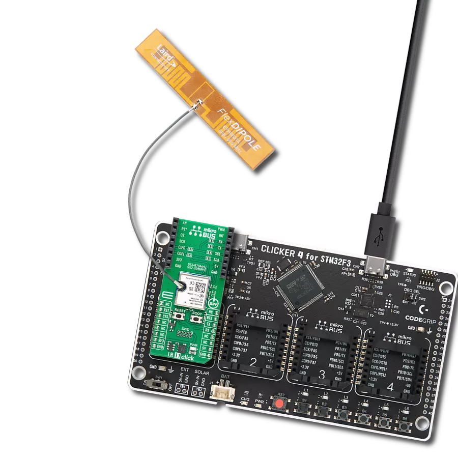
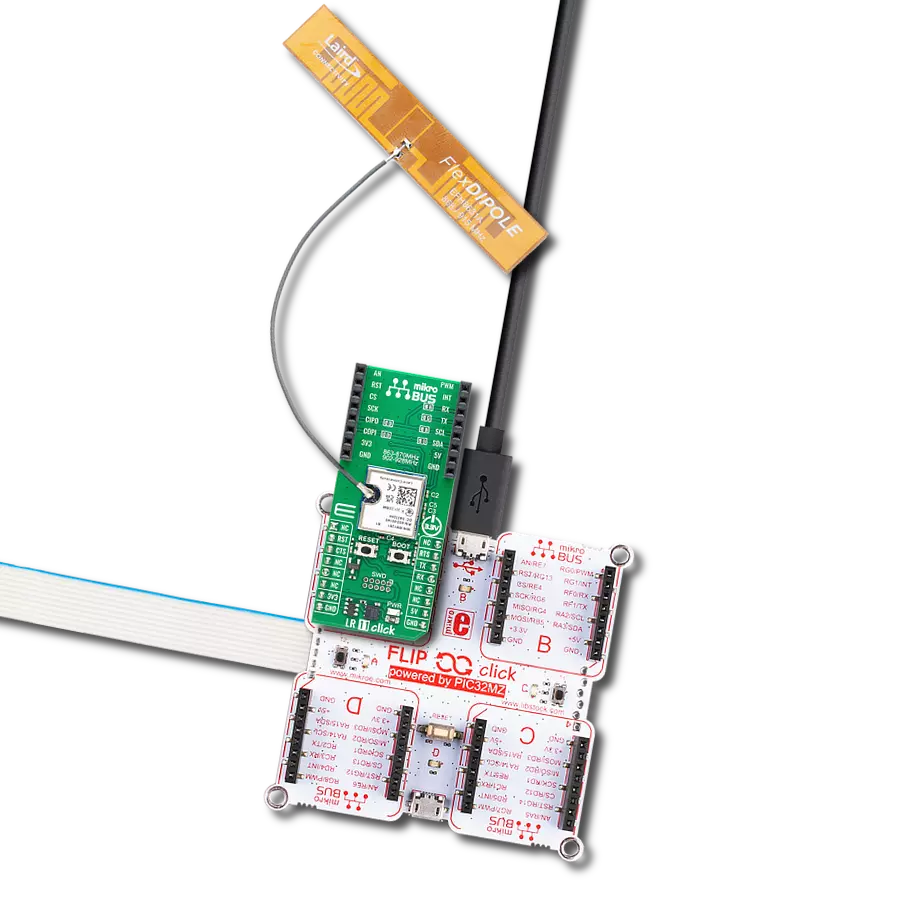
LR 6 Click is based on the Ra-01S, a LoRa™ wireless radio frequency module from Ai-Thinker Technology, designed for ultra-long-distance spread-spectrum communication. The Ra-01S module uses the SX1268 radio chip, primarily employing LoRa™ modulation technology for extended communication ranges. This module is known for its robust anti-interference capabilities and low current consumption, making it ideal for applications requiring reliable long-range communication. With Semtech's patented LoRa™ technology, the SX1268 chip offers exceptional sensitivity exceeding -148dBm and a power output of +22dBm. It supports multiple modulation methods, including FSK, GFSK, MSK, GMSK, LoRa™, and OOK, within the 433MHz frequency band (ranging from 410MHz to 525MHz).
Compared to traditional modulation technologies, LoRa™ offers significant advantages regarding anti-blocking and signal selection, addressing distance, interference, and power efficiency challenges. LR 6 Click is well-suited for various applications such as automatic meter reading, home and building automation, security systems, and remote irrigation systems, where long-distance communication and reliability are critical. This Click board™ communicates with the host MCU through a standard 4-wire SPI interface with frequencies up to 10MHz. In addition to the interface pins, the Ra-01S module uses the MD pin from the mikroBUS™ socket to select the TX or RX operational mode. It features a reset pin (RST) along with a RESET button for module resetting. This board also includes two unpopulated two-pin headers - one for
I/O digital signals for additional software configurations, another for an additional UART interface for RF port control, and a BSY pin alongside a red BUSY LED that indicates data transmission activity (module status). LR 6 Click also features the SMA antenna connector with an impedance of 50Ω, compatible with various antennas available from MIKROE, like the Rubber Antenna 433MHz, to enhance its connectivity. This Click board™ can be operated only with a 3.3V logic voltage level. The board must perform appropriate logic voltage level conversion before using MCUs with different logic levels. Also, it comes equipped with a library containing functions and an example code that can be used as a reference for further development.

Features overview
Development board
Nucleo-64 with STM32F030R8 MCU offers a cost-effective and adaptable platform for developers to explore new ideas and prototype their designs. This board harnesses the versatility of the STM32 microcontroller, enabling users to select the optimal balance of performance and power consumption for their projects. It accommodates the STM32 microcontroller in the LQFP64 package and includes essential components such as a user LED, which doubles as an ARDUINO® signal, alongside user and reset push-buttons, and a 32.768kHz crystal oscillator for precise timing operations. Designed with expansion and flexibility in mind, the Nucleo-64 board features an ARDUINO® Uno V3 expansion connector and ST morpho extension pin
headers, granting complete access to the STM32's I/Os for comprehensive project integration. Power supply options are adaptable, supporting ST-LINK USB VBUS or external power sources, ensuring adaptability in various development environments. The board also has an on-board ST-LINK debugger/programmer with USB re-enumeration capability, simplifying the programming and debugging process. Moreover, the board is designed to simplify advanced development with its external SMPS for efficient Vcore logic supply, support for USB Device full speed or USB SNK/UFP full speed, and built-in cryptographic features, enhancing both the power efficiency and security of projects. Additional connectivity is
provided through dedicated connectors for external SMPS experimentation, a USB connector for the ST-LINK, and a MIPI® debug connector, expanding the possibilities for hardware interfacing and experimentation. Developers will find extensive support through comprehensive free software libraries and examples, courtesy of the STM32Cube MCU Package. This, combined with compatibility with a wide array of Integrated Development Environments (IDEs), including IAR Embedded Workbench®, MDK-ARM, and STM32CubeIDE, ensures a smooth and efficient development experience, allowing users to fully leverage the capabilities of the Nucleo-64 board in their projects.

Microcontroller Overview
MCU Card / MCU

Architecture
ARM Cortex-M0
MCU Memory (KB)
64
Silicon Vendor
STMicroelectronics
Pin count
64
RAM (Bytes)
8192
You complete me!
Accessories
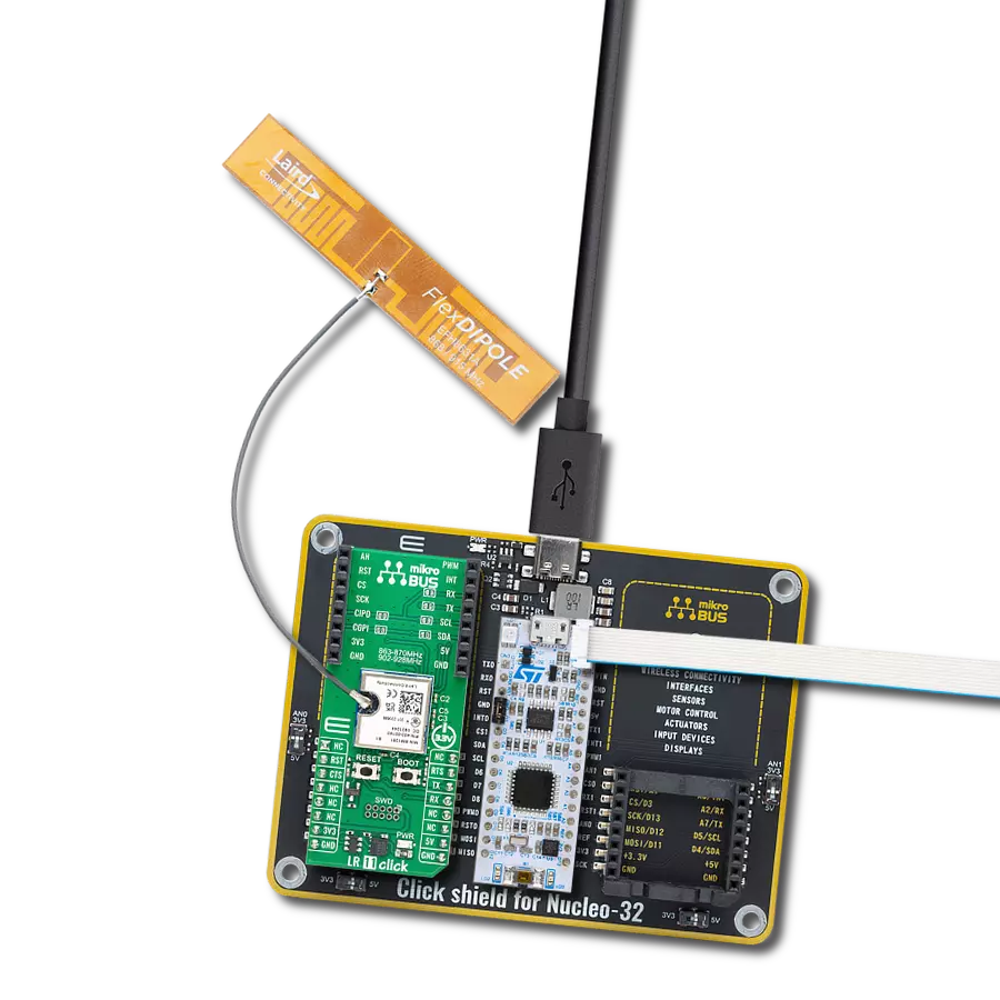
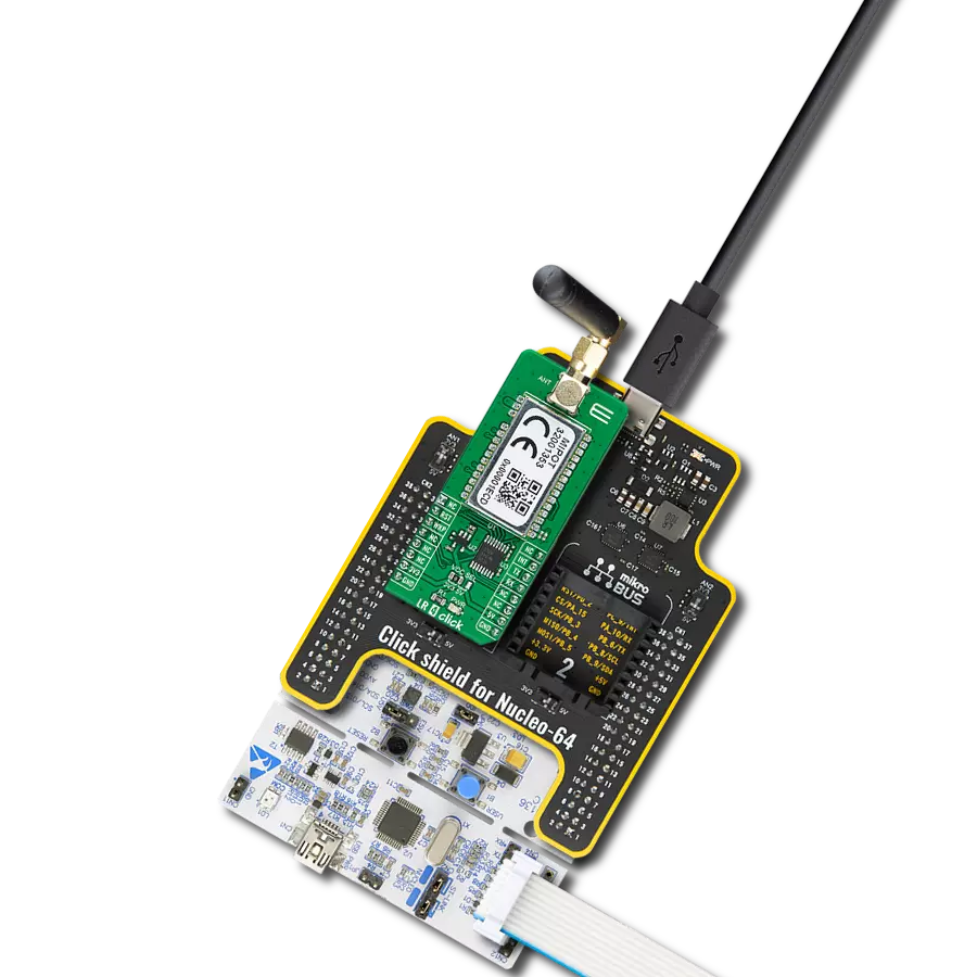
Click Shield for Nucleo-64 comes equipped with two proprietary mikroBUS™ sockets, allowing all the Click board™ devices to be interfaced with the STM32 Nucleo-64 board with no effort. This way, Mikroe allows its users to add any functionality from our ever-growing range of Click boards™, such as WiFi, GSM, GPS, Bluetooth, ZigBee, environmental sensors, LEDs, speech recognition, motor control, movement sensors, and many more. More than 1537 Click boards™, which can be stacked and integrated, are at your disposal. The STM32 Nucleo-64 boards are based on the microcontrollers in 64-pin packages, a 32-bit MCU with an ARM Cortex M4 processor operating at 84MHz, 512Kb Flash, and 96KB SRAM, divided into two regions where the top section represents the ST-Link/V2 debugger and programmer while the bottom section of the board is an actual development board. These boards are controlled and powered conveniently through a USB connection to program and efficiently debug the Nucleo-64 board out of the box, with an additional USB cable connected to the USB mini port on the board. Most of the STM32 microcontroller pins are brought to the IO pins on the left and right edge of the board, which are then connected to two existing mikroBUS™ sockets. This Click Shield also has several switches that perform functions such as selecting the logic levels of analog signals on mikroBUS™ sockets and selecting logic voltage levels of the mikroBUS™ sockets themselves. Besides, the user is offered the possibility of using any Click board™ with the help of existing bidirectional level-shifting voltage translators, regardless of whether the Click board™ operates at a 3.3V or 5V logic voltage level. Once you connect the STM32 Nucleo-64 board with our Click Shield for Nucleo-64, you can access hundreds of Click boards™, working with 3.3V or 5V logic voltage levels.

Right angle 433MHz rubber antenna boasts a frequency range of 433MHz, ensuring optimal performance within this spectrum. With a 50Ohm impedance, it facilitates efficient signal transmission. The antenna's vertical polarization enhances signal reception in a specific orientation. Featuring a 1.5dB gain, it can improve signal strength to some extent. The antenna can handle a maximum input power of 50W, making it suitable for various applications. Its compact 50mm length minimizes spatial requirements. Equipped with an SMA male connector, it easily interfaces with compatible devices. This antenna is an adaptable solution for wireless communication needs, particularly when vertical polarization is crucial.

Used MCU Pins
mikroBUS™ mapper
Take a closer look
Click board™ Schematic

Step by step
Project assembly
Start by selecting your development board and Click board™. Begin with the Nucleo-64 with STM32F030R8 MCU as your development board.


Track your results in real time
Application Output
1. Application Output - In Debug mode, the 'Application Output' window enables real-time data monitoring, offering direct insight into execution results. Ensure proper data display by configuring the environment correctly using the provided tutorial.

2. UART Terminal - Use the UART Terminal to monitor data transmission via a USB to UART converter, allowing direct communication between the Click board™ and your development system. Configure the baud rate and other serial settings according to your project's requirements to ensure proper functionality. For step-by-step setup instructions, refer to the provided tutorial.

3. Plot Output - The Plot feature offers a powerful way to visualize real-time sensor data, enabling trend analysis, debugging, and comparison of multiple data points. To set it up correctly, follow the provided tutorial, which includes a step-by-step example of using the Plot feature to display Click board™ readings. To use the Plot feature in your code, use the function: plot(*insert_graph_name*, variable_name);. This is a general format, and it is up to the user to replace 'insert_graph_name' with the actual graph name and 'variable_name' with the parameter to be displayed.

Software Support
Library Description
This library contains API for LR 6 Click driver.
Key functions:
lr6_send_data- This function sends a desired number of data bytes to the buffer by using the selected mode using the SPI serial interface.lr6_receive_data- This function receives a desired number of data bytes to the buffer by using the SPI serial interface.lr6_set_lr_config- This function performs the desired LoRa configuration by using the SPI serial interface.
Open Source
Code example
The complete application code and a ready-to-use project are available through the NECTO Studio Package Manager for direct installation in the NECTO Studio. The application code can also be found on the MIKROE GitHub account.
/*!
 * @file main.c
 * @brief LR 6 Click example
 *
 * # Description
 * This example demonstrates the use of LR 6 Click board by processing
 * the incoming data and displaying them on the USB UART.
 *
 * The demo application is composed of two sections :
 *
 * ## Application Init
 * Initialization of SPI module and log UART.
 * After driver initialization, the app executes a default configuration.
 *
 * ## Application Task
 * The demo application is an echo example that sends a demo LoRa packet string
 * and receives and processes all incoming data.
 * Results are being sent to the UART Terminal, where you can track their changes.
 *
 * @author Nenad Filipovic
 *
 */

#include "board.h"
#include "log.h"
#include "lr6.h"

static lr6_t lr6;
static log_t logger;

// Demo string to be sent
#define LR6_DEMO_TEXT            "MikroE\r\n"

void application_init ( void )
{
    log_cfg_t log_cfg;  /**< Logger config object. */
    lr6_cfg_t lr6_cfg;  /**< Click config object. */

    /**
     * Logger initialization.
     * Default baud rate: 115200
     * Default log level: LOG_LEVEL_DEBUG
     * @note If USB_UART_RX and USB_UART_TX
     * are defined as HAL_PIN_NC, you will
     * need to define them manually for log to work.
     * See @b LOG_MAP_USB_UART macro definition for detailed explanation.
     */
    LOG_MAP_USB_UART( log_cfg );
    log_init( &logger, &log_cfg );
    log_info( &logger, " Application Init " );

    // Click initialization.
    lr6_cfg_setup( &lr6_cfg );
    LR6_MAP_MIKROBUS( lr6_cfg, MIKROBUS_1 );
    if ( SPI_MASTER_ERROR == lr6_init( &lr6, &lr6_cfg ) )
    {
        log_error( &logger, " Communication init." );
        for ( ; ; );
    }

    if ( LR6_ERROR == lr6_default_cfg ( &lr6 ) )
    {
        log_error( &logger, " Default configuration." );
        for ( ; ; );
    }

    log_info( &logger, " Application Task " );
    log_printf( &logger, " --------------------\r\n" );
}

void application_task ( void )
{
    uint8_t rx_data[ 255 ] = { 0 };
    if ( LR6_OK == lr6_send_data( &lr6, LR6_DEMO_TEXT, strlen( LR6_DEMO_TEXT ), LR6_TX_MODE_SYNC ) )
    {
        log_info( &logger, " Send - success" );
        uint8_t rx_len = 0;
        do
        {
            if ( LR6_OK == lr6_receive_data( &lr6, rx_data, strlen( LR6_DEMO_TEXT ), &rx_len ) )
            {
                if ( rx_len > 0 )
                {
                    log_info( &logger, " Receive - success" );
                    log_printf( &logger, " > Receive: " );
                    for ( uint8_t cnt = 0; cnt < strlen( LR6_DEMO_TEXT ); cnt++ )
                    {
                        log_printf( &logger, "%c", rx_data[ cnt ] );
                    }

                    int8_t rssi, snr;
                    if ( LR6_OK == lr6_get_packet_status( &lr6, &rssi, &snr ) )
                    {
                        log_printf( &logger, " Rssi Pkt: %d dBm\r\n", ( int16_t ) rssi );
                        log_printf( &logger, " Snr Pkt : %d dB\r\n", ( int16_t ) snr );
                        log_printf( &logger, " --------------------\r\n" );
                        break;
                    }
                }
            }
        }
        while ( rx_len == 0 );
    }
    else
    {
        log_info( &logger, "Send - fail" );
    }
    Delay_ms ( 1000 );
}

int main ( void )
{
    /* Do not remove this line or clock might not be set correctly. */
    #ifdef PREINIT_SUPPORTED
    preinit();
    #endif

    application_init( );

    for ( ; ; )
    {
        application_task( );
    }

    return 0;
}

// ------------------------------------------------------------------------ END
Additional Support
Resources
Category:LoRa