Achieve long-range, low-power communication ideal for IoT applications with RA-08 and STM32F091RC
LoRa module for ultra-long distance spread spectrum communications
Published Apr 04, 2024
Click board™
LR 9 Click
Dev. board
Nucleo-64 with STM32F091RC MCU
Compiler
NECTO Studio
MCU
STM32F091RC
Ideal for sectors requiring long-distance, low-power communication, such as smart metering, supply chain and logistics, home automation, and security systems
A
A
Hardware Overview
How does it work?
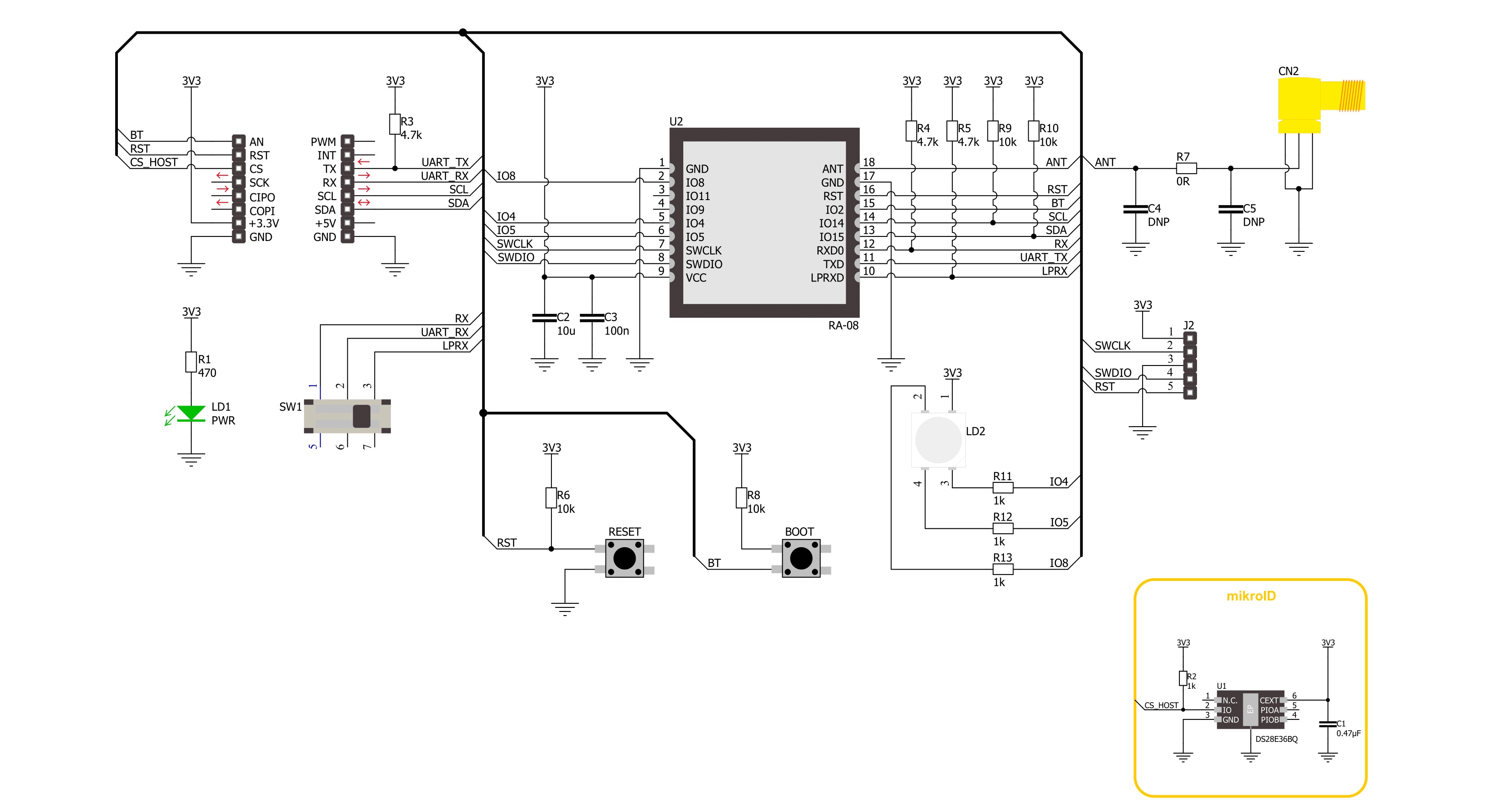
LR 9 Click is based on the RA-08, a LoRaWAN module from Ai-Thinker Technology. This module is made for ultra-long-range spread spectrum communication tasks powered by the ASR6601. The ASR6601, an LPWAN wireless communication system-on-chip (SoC), combines RF transceivers, modems, and a 32-bit RISC microcontroller (MCU). The embedded MCU, leveraging an ARM core, operates at a frequency of 48MHz. The RA-08 is designed to work with LoRa modulation and the conventional (G)FSK modulation within the LPWAN domain. Furthermore, it supports BPSK and (G)MSK modulation for transmission, with the receiver accommodating (G)MSK modulation. Designed for LPWAN applications, the RA-08 module delivers long-distance, ultra-low power connectivity. It finds its applications in various sectors, including smart metering, supply chain and logistics management, building automation for homes, security systems, and remote-controlled
irrigation systems. Diving deeper into the specifics, the module supports a frequency range from 410MHz to 525MHz and can transmit at a maximum power of +22dBm. It boasts embedded storage with 128KB of FLASH and 16KB of SRAM, alongside support for several sleep modes, with a deep sleep current as low as 0.9uA. Additional functionalities of the LR 9 Click include communication capabilities with the host MCU via a UART interface, set by default to a baud rate of 115200bps. A switch on the board allows the selection of the UART interface's function—either as the main serial communication port for exchanging AT commands (in the LPRX position) or as a serial port for firmware flashing (in the RX position). Moreover, for developers looking to build their software from scratch, the module also includes I2C communication capabilities. The board does not limit itself to UART and I2C interface pins; it also features pins like the RST pin for module
resetting (which can also be achieved through a RESET button) and a BT pin for firmware flashing (accessible through a BOOT button). This frees programming and software development through the SWD interface pins on the board's right side. Also, an RGB LED serves as a module status indicator and is configurable by the user. LR 9 Click also features the SMA antenna connector with an impedance of 50Ω, compatible with various antennas available from MIKROE, like the Rubber Antenna 433MHz, to enhance its connectivity. This Click board™ can be operated only with a 3.3V logic voltage level. The board must perform appropriate logic voltage level conversion before using MCUs with different logic levels. Also, it comes equipped with a library containing functions and an example code that can be used as a reference for further development.

Features overview
Development board
Nucleo-64 with STM32F091RC MCU offers a cost-effective and adaptable platform for developers to explore new ideas and prototype their designs. This board harnesses the versatility of the STM32 microcontroller, enabling users to select the optimal balance of performance and power consumption for their projects. It accommodates the STM32 microcontroller in the LQFP64 package and includes essential components such as a user LED, which doubles as an ARDUINO® signal, alongside user and reset push-buttons, and a 32.768kHz crystal oscillator for precise timing operations. Designed with expansion and flexibility in mind, the Nucleo-64 board features an ARDUINO® Uno V3 expansion connector and ST morpho extension pin
headers, granting complete access to the STM32's I/Os for comprehensive project integration. Power supply options are adaptable, supporting ST-LINK USB VBUS or external power sources, ensuring adaptability in various development environments. The board also has an on-board ST-LINK debugger/programmer with USB re-enumeration capability, simplifying the programming and debugging process. Moreover, the board is designed to simplify advanced development with its external SMPS for efficient Vcore logic supply, support for USB Device full speed or USB SNK/UFP full speed, and built-in cryptographic features, enhancing both the power efficiency and security of projects. Additional connectivity is
provided through dedicated connectors for external SMPS experimentation, a USB connector for the ST-LINK, and a MIPI® debug connector, expanding the possibilities for hardware interfacing and experimentation. Developers will find extensive support through comprehensive free software libraries and examples, courtesy of the STM32Cube MCU Package. This, combined with compatibility with a wide array of Integrated Development Environments (IDEs), including IAR Embedded Workbench®, MDK-ARM, and STM32CubeIDE, ensures a smooth and efficient development experience, allowing users to fully leverage the capabilities of the Nucleo-64 board in their projects.

Microcontroller Overview
MCU Card / MCU

Architecture
ARM Cortex-M0
MCU Memory (KB)
256
Silicon Vendor
STMicroelectronics
Pin count
64
RAM (Bytes)
32768
You complete me!
Accessories
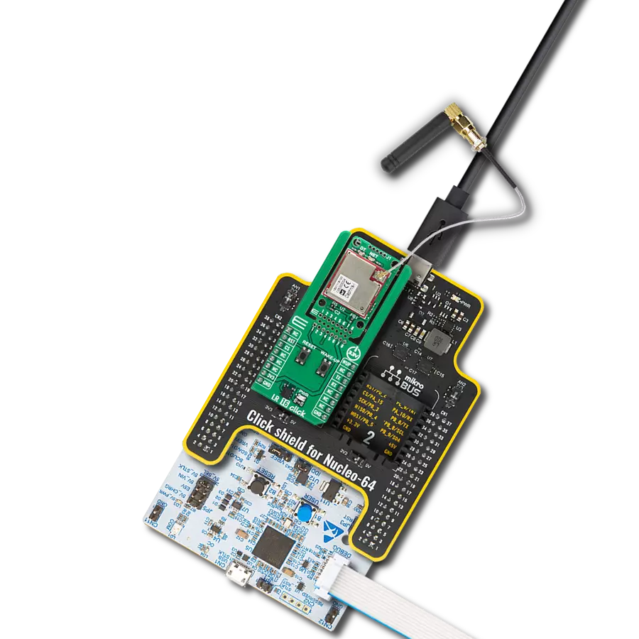
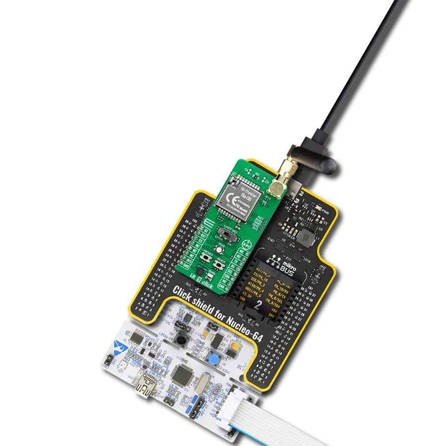
Click Shield for Nucleo-64 comes equipped with two proprietary mikroBUS™ sockets, allowing all the Click board™ devices to be interfaced with the STM32 Nucleo-64 board with no effort. This way, Mikroe allows its users to add any functionality from our ever-growing range of Click boards™, such as WiFi, GSM, GPS, Bluetooth, ZigBee, environmental sensors, LEDs, speech recognition, motor control, movement sensors, and many more. More than 1537 Click boards™, which can be stacked and integrated, are at your disposal. The STM32 Nucleo-64 boards are based on the microcontrollers in 64-pin packages, a 32-bit MCU with an ARM Cortex M4 processor operating at 84MHz, 512Kb Flash, and 96KB SRAM, divided into two regions where the top section represents the ST-Link/V2 debugger and programmer while the bottom section of the board is an actual development board. These boards are controlled and powered conveniently through a USB connection to program and efficiently debug the Nucleo-64 board out of the box, with an additional USB cable connected to the USB mini port on the board. Most of the STM32 microcontroller pins are brought to the IO pins on the left and right edge of the board, which are then connected to two existing mikroBUS™ sockets. This Click Shield also has several switches that perform functions such as selecting the logic levels of analog signals on mikroBUS™ sockets and selecting logic voltage levels of the mikroBUS™ sockets themselves. Besides, the user is offered the possibility of using any Click board™ with the help of existing bidirectional level-shifting voltage translators, regardless of whether the Click board™ operates at a 3.3V or 5V logic voltage level. Once you connect the STM32 Nucleo-64 board with our Click Shield for Nucleo-64, you can access hundreds of Click boards™, working with 3.3V or 5V logic voltage levels.

Right angle 433MHz rubber antenna boasts a frequency range of 433MHz, ensuring optimal performance within this spectrum. With a 50Ohm impedance, it facilitates efficient signal transmission. The antenna's vertical polarization enhances signal reception in a specific orientation. Featuring a 1.5dB gain, it can improve signal strength to some extent. The antenna can handle a maximum input power of 50W, making it suitable for various applications. Its compact 50mm length minimizes spatial requirements. Equipped with an SMA male connector, it easily interfaces with compatible devices. This antenna is an adaptable solution for wireless communication needs, particularly when vertical polarization is crucial.

Used MCU Pins
mikroBUS™ mapper
Take a closer look
Click board™ Schematic
Step by step
Project assembly
Start by selecting your development board and Click board™. Begin with the Nucleo-64 with STM32F091RC MCU as your development board.


Software Support
Library Description
This library contains API for LR 9 Click driver.
Key functions:
lr9_send_data_frame- This function sends the desired data frame by using the UART serial interfacelr9_inquire_command- Using the UART serial interface, this function writes the desired query command with or without the included equals symbollr9_write_command- This function writes a desired command and parameter by using the UART serial interface
Open Source
Code example
The complete application code and a ready-to-use project are available through the NECTO Studio Package Manager for direct installation in the NECTO Studio. The application code can also be found on the MIKROE GitHub account.
/*!
 * @file main.c
 * @brief LR 9 Click Example.
 *
 * # Description
 * This example demonstrates the use of LR 9 Click board by processing
 * the incoming data and displaying them on the USB UART.
 *
 * The demo application is composed of two sections :
 *
 * ## Application Init
 * Initializes the driver and performs a hardware reset of the device.
 *
 * ## Application Task
 * Depending on the selected mode, the application demo
 * receives and processes all incoming data or sends the LoRa packet demo string.
 * Results are being sent to the UART Terminal, where you can track their changes.
 *
 * ## Additional Function
 * - static void lr9_clear_app_buf ( void )
 * - static void lr9_log_app_buf ( void )
 * - static void lr9_log_receiver ( void )
 * - static void lr9_log_response ( void )
 * - static err_t lr9_process ( lr9_t *ctx )
 *
 * @author Nenad Filipovic
 *
 */

#include "board.h"
#include "log.h"
#include "lr9.h"
#include "conversions.h"

// Comment the line below to switch application mode to receiver
#define DEMO_APP_TRANSMITTER

// Default RF configuration
#define LR9_RF_CFG_DEFAULT_TX       "433000000,1,1,1,22,1"
#define LR9_RF_CFG_DEFAULT_RX       "433000000,1,1,1,1"
#define LR9_DEMO_STRING             "MikroE"

// Receiver string sequences
#define PROCESS_START_RECEIVE       "Recv:"
#define PROCESS_ATDTRX              "AT"

// Response timeout
#define RESPONSE_TIMEOUT            100000

// Application buffer size
#define APP_BUFFER_SIZE             500
#define PROCESS_BUFFER_SIZE         200

static lr9_t lr9;
static log_t logger;

static uint8_t app_buf[ APP_BUFFER_SIZE ] = { 0 };
static int32_t app_buf_len = 0;

/**
 * @brief LR 9 clearing application buffer.
 * @details This function clears memory of application buffer and reset its length.
 * @note None.
 */
static void lr9_clear_app_buf ( void );

/**
 * @brief LR 9 log application buffer.
 * @details This function logs data from application buffer to USB UART.
 * @note None.
 */
static void lr9_log_app_buf ( void );

/**
 * @brief LR 9 log receiver data.
 * @details This function logs data from receiver application buffer to USB UART.
 * @note None.
 */
static void lr9_log_receiver ( void );

/**
 * @brief LR 9 log response.
 * @details This function reads data from device and
 * concatenates and logs data to application buffer to USB UART.
 * @note None.
 */
static void lr9_log_response ( void );

/**
 * @brief LR 9 data reading function.
 * @details This function reads data from device and concatenates data to application buffer.
 * @param[in] ctx : Click context object.
 * See #lr9_t object definition for detailed explanation.
 * @return @li @c  0 - Read some data.
 *         @li @c -1 - Nothing is read.
 * See #err_t definition for detailed explanation.
 * @note None.
 */
static err_t lr9_process ( lr9_t *ctx );

void application_init ( void )
{
    log_cfg_t log_cfg;  /**< Logger config object. */
    lr9_cfg_t lr9_cfg;  /**< Click config object. */

    /**
     * Logger initialization.
     * Default baud rate: 115200
     * Default log level: LOG_LEVEL_DEBUG
     * @note If USB_UART_RX and USB_UART_TX
     * are defined as HAL_PIN_NC, you will
     * need to define them manually for log to work.
     * See @b LOG_MAP_USB_UART macro definition for detailed explanation.
     */
    LOG_MAP_USB_UART( log_cfg );
    log_init( &logger, &log_cfg );
    log_info( &logger, " Application Init " );

    // Click initialization.
    lr9_cfg_setup( &lr9_cfg );
    LR9_MAP_MIKROBUS( lr9_cfg, MIKROBUS_1 );
    if ( UART_ERROR == lr9_init( &lr9, &lr9_cfg ) )
    {
        log_error( &logger, " Communication init." );
        for ( ; ; );
    }

    lr9_hw_reset( &lr9 );
    Delay_ms ( 500 );

    lr9_inquire_command( &lr9, LR9_CMD_CTXADDRSET, LR9_EQUAL_ENABLE );
    lr9_log_response( );
    Delay_ms ( 500 );

    lr9_inquire_command( &lr9, LR9_CMD_CADDRSET, LR9_EQUAL_ENABLE );
    lr9_log_response( );
    Delay_ms ( 500 );

#ifdef DEMO_APP_TRANSMITTER
    log_printf( &logger, " > Transmitter < \r\n" );
    lr9_write_command( &lr9, LR9_CMD_CTX , LR9_RF_CFG_DEFAULT_TX );
    lr9_log_response( );
    Delay_ms ( 500 );
#else
    log_printf( &logger, " > Receiver < \r\n" );
    lr9_write_command( &lr9, LR9_CMD_CRXS , LR9_RF_CFG_DEFAULT_RX );
    lr9_log_response( );
    Delay_ms ( 500 );
#endif

    lr9_log_response( );
    Delay_ms ( 500 );
}

void application_task ( void )
{
#ifdef DEMO_APP_TRANSMITTER
    lr9_send_data_frame( &lr9, LR9_DTRX_CONFIG_DATA, LR9_NB_TRIALS_2, LR9_DEMO_STRING );
    lr9_log_response( );
    Delay_ms ( 1000 );
    Delay_ms ( 1000 );
#else
    lr9_log_receiver( );
#endif
}

int main ( void )
{
    /* Do not remove this line or clock might not be set correctly. */
    #ifdef PREINIT_SUPPORTED
    preinit();
    #endif

    application_init( );

    for ( ; ; )
    {
        application_task( );
    }

    return 0;
}

static void lr9_clear_app_buf ( void )
{
    memset( app_buf, 0, app_buf_len );
    app_buf_len = 0;
}

static void lr9_log_app_buf ( void )
{
    for ( int32_t buf_cnt = 0; buf_cnt < app_buf_len; buf_cnt++ )
    {
        log_printf( &logger, "%c", app_buf[ buf_cnt ] );
    }
}

static void lr9_log_receiver ( void )
{
    uint32_t timeout_cnt = 0;
    lr9_clear_app_buf( );
    lr9_process( &lr9 );
    while ( 0 == strstr( app_buf, PROCESS_START_RECEIVE ) )
    {
        lr9_process( &lr9 );
        if ( timeout_cnt++ > RESPONSE_TIMEOUT )
        {
            lr9_clear_app_buf( );
            log_printf( &logger, " Timeout\r\n" );
            break;
        }
        Delay_ms ( 1 );
    }
    lr9_process( &lr9 );
    if ( strstr( app_buf, PROCESS_ATDTRX ) )
    {
        log_printf( &logger, " Receive: " );
        for ( int32_t buf_cnt = 15; buf_cnt < 15 + strlen( LR9_DEMO_STRING ); buf_cnt++ )
        {
            log_printf( &logger, "%c", app_buf[ buf_cnt ] );
        }
        log_printf( &logger, "\r\n" );
    }
    lr9_clear_app_buf( );
}

static void lr9_log_response ( void )
{
    if ( LR9_OK == lr9_process( &lr9 ) )
    {
        lr9_log_app_buf( );
        lr9_clear_app_buf( );
    }
}

static err_t lr9_process ( lr9_t *ctx )
{
    uint8_t rx_buf[ PROCESS_BUFFER_SIZE ] = { 0 };
    int32_t overflow_bytes = 0;
    int32_t rx_cnt = 0;
    int32_t rx_size = lr9_generic_read( ctx, rx_buf, PROCESS_BUFFER_SIZE );
    if ( ( rx_size > 0 ) && ( rx_size <= APP_BUFFER_SIZE ) )
    {
        if ( ( app_buf_len + rx_size ) > APP_BUFFER_SIZE )
        {
            overflow_bytes = ( app_buf_len + rx_size ) - APP_BUFFER_SIZE;
            app_buf_len = APP_BUFFER_SIZE - rx_size;
            memmove ( app_buf, &app_buf[ overflow_bytes ], app_buf_len );
            memset ( &app_buf[ app_buf_len ], 0, overflow_bytes );
        }
        for ( rx_cnt = 0; rx_cnt < rx_size; rx_cnt++ )
        {
            if ( rx_buf[ rx_cnt ] )
            {
                app_buf[ app_buf_len++ ] = rx_buf[ rx_cnt ];
            }
        }
        return LR9_OK;
    }
    return LR9_ERROR;
}

// ------------------------------------------------------------------------ END
Additional Support
Resources
Category:LoRa