Measure the speed and rotation of a spinning object with A17501 and STM32F410RB
Dual-output differential speed and direction sensing solution

Published Oct 08, 2024
Click board™
Speed Sense Click
Dev. board
Nucleo 64 with STM32F410RB MCU
Compiler
NECTO Studio
MCU
STM32F410RB
Easily perform rotational position sensing of a ring magnet target in automotive and industrial electric motor applications, often with specific application and safety requirements
A
A
Hardware Overview
How does it work?
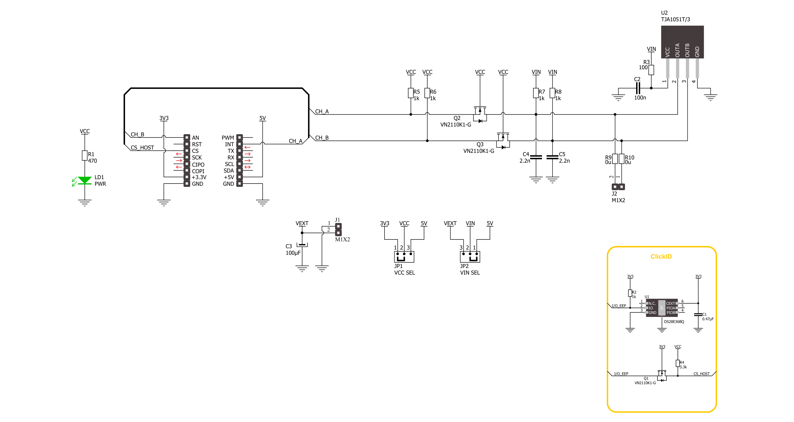
Speed Sens Click is based on the A17501, a dual output differential speed and direction sensor from Allegro Microsystems. The sensor consists of three Hall elements incorporated in such a way as to create two independent differential channels. The differential signals are used to produce a highly accurate speed output and, if desired, provide information on the direction of rotation. The advanced self-calibration technique with the digital tracking of the signal results in accurate switch points over the air gap, speed, and temperature. The sensor is immune to common external
magnetic disturbance and is ideally suited for asynchronous electric motor applications. When properly back-biased, the sensor is intended for use with ring magnets or ferromagnetic targets. It poses a temperature-compensated amplifier, as well as a full-range ADC. Besides operating on 5V from the mikroBUS™ socket power rail, you can also add an external power supply over the VEXT connector from 4 up to 24V. The selection can be made over the VIN SEL. Speed Sens Click uses general-purpose IOs to interrupt the host MCU when detecting the magnet on a spinning wheel.
The output channel pins are labeled CHA and CHB. There is also an external header with these channels for connecting an external device (relay, LED, and more). This Click board™ can operate with either 3.3V or 5V logic voltage levels selected via the VCC SEL jumper. This way, both 3.3V and 5V capable MCUs can use the communication lines properly. Also, this Click board™ comes equipped with a library containing easy-to-use functions and an example code that can be used as a reference for further development.

Features overview
Development board
Nucleo-64 with STM32F410RB MCU offers a cost-effective and adaptable platform for developers to explore new ideas and prototype their designs. This board harnesses the versatility of the STM32 microcontroller, enabling users to select the optimal balance of performance and power consumption for their projects. It accommodates the STM32 microcontroller in the LQFP64 package and includes essential components such as a user LED, which doubles as an ARDUINO® signal, alongside user and reset push-buttons, and a 32.768kHz crystal oscillator for precise timing operations. Designed with expansion and flexibility in mind, the Nucleo-64 board features an ARDUINO® Uno V3 expansion connector and ST morpho extension pin
headers, granting complete access to the STM32's I/Os for comprehensive project integration. Power supply options are adaptable, supporting ST-LINK USB VBUS or external power sources, ensuring adaptability in various development environments. The board also has an on-board ST-LINK debugger/programmer with USB re-enumeration capability, simplifying the programming and debugging process. Moreover, the board is designed to simplify advanced development with its external SMPS for efficient Vcore logic supply, support for USB Device full speed or USB SNK/UFP full speed, and built-in cryptographic features, enhancing both the power efficiency and security of projects. Additional connectivity is
provided through dedicated connectors for external SMPS experimentation, a USB connector for the ST-LINK, and a MIPI® debug connector, expanding the possibilities for hardware interfacing and experimentation. Developers will find extensive support through comprehensive free software libraries and examples, courtesy of the STM32Cube MCU Package. This, combined with compatibility with a wide array of Integrated Development Environments (IDEs), including IAR Embedded Workbench®, MDK-ARM, and STM32CubeIDE, ensures a smooth and efficient development experience, allowing users to fully leverage the capabilities of the Nucleo-64 board in their projects.

Microcontroller Overview
MCU Card / MCU

Architecture
ARM Cortex-M4
MCU Memory (KB)
128
Silicon Vendor
STMicroelectronics
Pin count
64
RAM (Bytes)
32768
You complete me!
Accessories
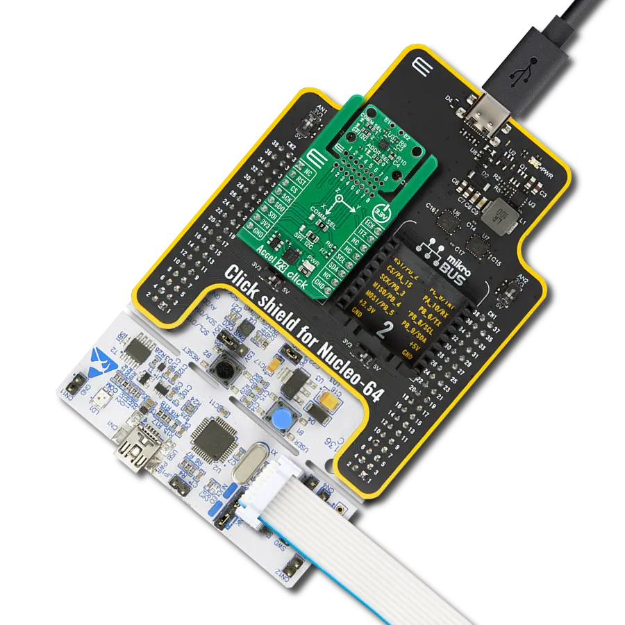
Click Shield for Nucleo-64 comes equipped with two proprietary mikroBUS™ sockets, allowing all the Click board™ devices to be interfaced with the STM32 Nucleo-64 board with no effort. This way, Mikroe allows its users to add any functionality from our ever-growing range of Click boards™, such as WiFi, GSM, GPS, Bluetooth, ZigBee, environmental sensors, LEDs, speech recognition, motor control, movement sensors, and many more. More than 1537 Click boards™, which can be stacked and integrated, are at your disposal. The STM32 Nucleo-64 boards are based on the microcontrollers in 64-pin packages, a 32-bit MCU with an ARM Cortex M4 processor operating at 84MHz, 512Kb Flash, and 96KB SRAM, divided into two regions where the top section represents the ST-Link/V2 debugger and programmer while the bottom section of the board is an actual development board. These boards are controlled and powered conveniently through a USB connection to program and efficiently debug the Nucleo-64 board out of the box, with an additional USB cable connected to the USB mini port on the board. Most of the STM32 microcontroller pins are brought to the IO pins on the left and right edge of the board, which are then connected to two existing mikroBUS™ sockets. This Click Shield also has several switches that perform functions such as selecting the logic levels of analog signals on mikroBUS™ sockets and selecting logic voltage levels of the mikroBUS™ sockets themselves. Besides, the user is offered the possibility of using any Click board™ with the help of existing bidirectional level-shifting voltage translators, regardless of whether the Click board™ operates at a 3.3V or 5V logic voltage level. Once you connect the STM32 Nucleo-64 board with our Click Shield for Nucleo-64, you can access hundreds of Click boards™, working with 3.3V or 5V logic voltage levels.

Used MCU Pins
mikroBUS™ mapper
Take a closer look
Click board™ Schematic
Step by step
Project assembly
Start by selecting your development board and Click board™. Begin with the Nucleo 64 with STM32F410RB MCU as your development board.


Software Support
Library Description
This library contains API for Speed Sense Click driver.
Key functions:
speedsense_get_speed- This function reads the state of the CHA pin used for speed output protocolsspeedsense_get_direction- This function reads the state of the CHB pin used for direction output protocols
Open Source
Code example
The complete application code and a ready-to-use project are available through the NECTO Studio Package Manager for direct installation in the NECTO Studio. The application code can also be found on the MIKROE GitHub account.
/*!
 * @file main.c
 * @brief Speed Sense Click Example.
 *
 * # Description
 * This library contains the API for the Speed Sense Click driver
 * for the speed and direction signal state detection for every magnetic pole pair.
 *
 * The demo application is composed of two sections :
 *
 * ## Application Init
 * Initialization of GPIO and log UART.
 *
 * ## Application Task
 * This example demonstrates the use of the Speed Sense Click board.
 * The demo application displays the direction of movement and rotation speed (rotations per minute)
 * of the ring magnet with three pairs of rotating poles positioned in the sensor operating range.
 *
 *
 * @author Nenad Filipovic
 *
 */

#include "board.h"
#include "log.h"
#include "speedsense.h"

#define SPEEDSENSE_MAG_POLE_PAIRS    3
#define SPEEDSENSE_CALC_RMP          SPEEDSENSE_CNV_MIN_TO_MS / SPEEDSENSE_MAG_POLE_PAIRS

uint8_t start_measure = SPEEDSENSE_STOP_MEASURE;
uint32_t time_cnt = 0;
uint32_t signal_duration = 0;
uint32_t start_timer = 0;

static speedsense_t speedsense;   /**< Speed Sense Click driver object. */
static log_t logger;    /**< Logger object. */

void application_init ( void )
{
    log_cfg_t log_cfg;  /**< Logger config object. */
    speedsense_cfg_t speedsense_cfg;  /**< Click config object. */

    /**
     * Logger initialization.
     * Default baud rate: 115200
     * Default log level: LOG_LEVEL_DEBUG
     * @note If USB_UART_RX and USB_UART_TX
     * are defined as HAL_PIN_NC, you will
     * need to define them manually for log to work.
     * See @b LOG_MAP_USB_UART macro definition for detailed explanation.
     */
    LOG_MAP_USB_UART( log_cfg );
    log_init( &logger, &log_cfg );
    log_info( &logger, " Application Init " );

    // Click initialization.
    speedsense_cfg_setup( &speedsense_cfg );
    SPEEDSENSE_MAP_MIKROBUS( speedsense_cfg, MIKROBUS_1 );
    if ( DIGITAL_OUT_UNSUPPORTED_PIN == speedsense_init( &speedsense, &speedsense_cfg ) )
    {
        log_error( &logger, " Communication init." );
        for ( ; ; );
    }

    log_info( &logger, " Application Task " );
    log_printf( &logger, "-----------------------\r\n" );
}

void application_task ( void )
{
    uint8_t direction = 0, speed = 0;
    speed = speedsense_get_speed( &speedsense );
    direction = speedsense_get_direction( &speedsense );

    if ( start_measure & speed )
    {
        signal_duration = time_cnt - start_timer;
        start_timer = time_cnt;

        if ( SPEEDSENSE_DIR_STATE_FWD == direction )
        {
            log_printf( &logger, " Direction: Forward\r\n" );
        }
        else
        {
            log_printf( &logger, " Direction: Reverse\r\n" );
        }
        log_printf( &logger, " Speed: %.2f [rpm]\r\n", SPEEDSENSE_CALC_RMP / signal_duration );
        log_printf( &logger, " Duration: %lu [ms]\r\n", signal_duration );
        log_printf( &logger, " Time: %lu  [ms]\r\n", time_cnt );
        log_printf( &logger, "-----------------------\r\n" );
        start_measure = SPEEDSENSE_STOP_MEASURE;
    }
    else if ( ( !start_measure ) & ( !speed ) )
    {
        start_measure = SPEEDSENSE_START_NEW_MEASURE;
    }

    time_cnt++;
    Delay_ms ( 1 );
}

int main ( void )
{
    /* Do not remove this line or clock might not be set correctly. */
    #ifdef PREINIT_SUPPORTED
    preinit();
    #endif

    application_init( );

    for ( ; ; )
    {
        application_task( );
    }

    return 0;
}

// ------------------------------------------------------------------------ END
Additional Support
Resources
Category:Motion