Easily implement LiDAR technology into your future projects with our TFmini solution and STM32F091RC
Your plug-and-play TFmini LiDAR solution

Published Feb 26, 2024
Click board™
TFmini Click
Dev. board
Nucleo-64 with STM32F091RC MCU
Compiler
NECTO Studio
MCU
STM32F091RC
With our TFmini adapter, we've engineered a game-changing solution that empowers engineers and innovators to integrate LiDAR technology into their projects, accelerating development and unlocking new possibilities in distance measurements
A
A
Hardware Overview
How does it work?
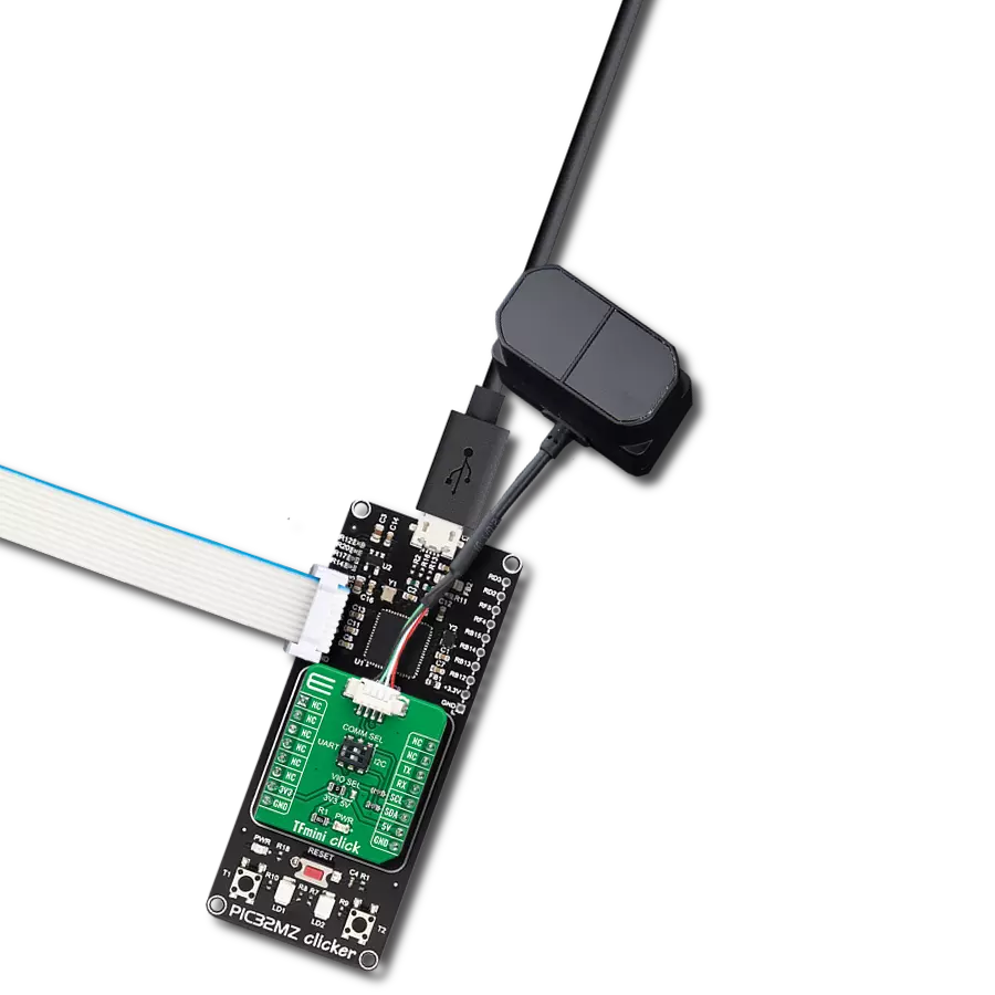
TFmini Click is an adapter Click board™ that simplifies the interface of the TFmini LiDAR module with the host MCU. This Click board™ represents a small PCB connected to the mikroBUS™ socket like any other Click board™, with a 1x4 1.25mm pitch connector used for the TFmini LiDAR sensor connection. Each connector pin corresponds to a pin of the TFmini LiDAR sensor, allowing easy pin access and manipulation while retaining a perfect connection quality at all times. This Click board™ allows users to upgrade their projects with a sensor capable of measuring the distance to an object, where different
measurement ranges can be achieved. As with all LiDAR sensors, the effective detection distance will vary depending on lighting conditions and the reflectivity of your target object. These sensors come with an IP65 enclosure rating, 100Hz frame rate, and 70Klux ambient light immunity and are suitable for various industrial environments like pedestrian detection, vehicle testing, and altitude. TFmini Click can use both UART and I2C interfaces, with commonly used UART RX and TX pins as its default communication protocol operating at 115200bps by default configuration to transmit and exchange data with the host MCU. The selection
can be made by positioning the SMD switch labeled COMM SEL in an appropriate position. Note that all the switch positions must be on the same side, or the Click board™ may become unresponsive. This Click board™ can operate with either 3.3V or 5V logic voltage levels selected via the VIO SEL jumper. This way, both 3.3V and 5V capable MCUs can use the communication lines properly. Also, this Click board™ comes equipped with a library containing easy-to-use functions and an example code that can be used as a reference for further development.


Features overview
Development board
Nucleo-64 with STM32F091RC MCU offers a cost-effective and adaptable platform for developers to explore new ideas and prototype their designs. This board harnesses the versatility of the STM32 microcontroller, enabling users to select the optimal balance of performance and power consumption for their projects. It accommodates the STM32 microcontroller in the LQFP64 package and includes essential components such as a user LED, which doubles as an ARDUINO® signal, alongside user and reset push-buttons, and a 32.768kHz crystal oscillator for precise timing operations. Designed with expansion and flexibility in mind, the Nucleo-64 board features an ARDUINO® Uno V3 expansion connector and ST morpho extension pin
headers, granting complete access to the STM32's I/Os for comprehensive project integration. Power supply options are adaptable, supporting ST-LINK USB VBUS or external power sources, ensuring adaptability in various development environments. The board also has an on-board ST-LINK debugger/programmer with USB re-enumeration capability, simplifying the programming and debugging process. Moreover, the board is designed to simplify advanced development with its external SMPS for efficient Vcore logic supply, support for USB Device full speed or USB SNK/UFP full speed, and built-in cryptographic features, enhancing both the power efficiency and security of projects. Additional connectivity is
provided through dedicated connectors for external SMPS experimentation, a USB connector for the ST-LINK, and a MIPI® debug connector, expanding the possibilities for hardware interfacing and experimentation. Developers will find extensive support through comprehensive free software libraries and examples, courtesy of the STM32Cube MCU Package. This, combined with compatibility with a wide array of Integrated Development Environments (IDEs), including IAR Embedded Workbench®, MDK-ARM, and STM32CubeIDE, ensures a smooth and efficient development experience, allowing users to fully leverage the capabilities of the Nucleo-64 board in their projects.

Microcontroller Overview
MCU Card / MCU

Architecture
ARM Cortex-M0
MCU Memory (KB)
256
Silicon Vendor
STMicroelectronics
Pin count
64
RAM (Bytes)
32768
You complete me!
Accessories
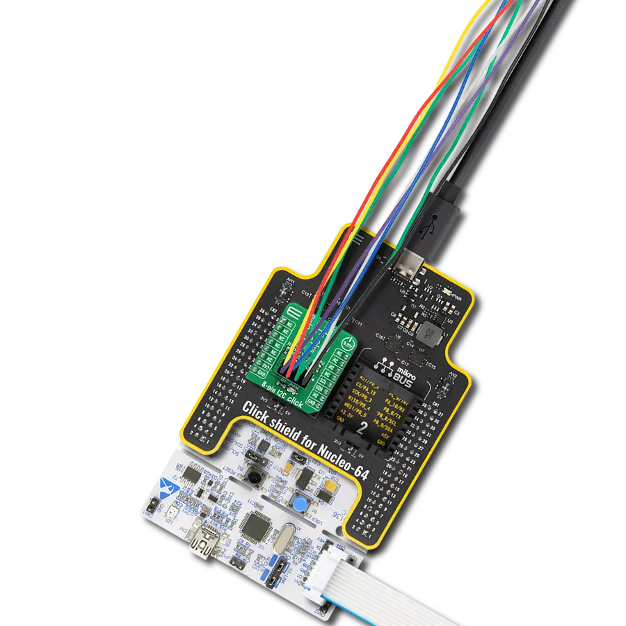
Click Shield for Nucleo-64 comes equipped with two proprietary mikroBUS™ sockets, allowing all the Click board™ devices to be interfaced with the STM32 Nucleo-64 board with no effort. This way, Mikroe allows its users to add any functionality from our ever-growing range of Click boards™, such as WiFi, GSM, GPS, Bluetooth, ZigBee, environmental sensors, LEDs, speech recognition, motor control, movement sensors, and many more. More than 1537 Click boards™, which can be stacked and integrated, are at your disposal. The STM32 Nucleo-64 boards are based on the microcontrollers in 64-pin packages, a 32-bit MCU with an ARM Cortex M4 processor operating at 84MHz, 512Kb Flash, and 96KB SRAM, divided into two regions where the top section represents the ST-Link/V2 debugger and programmer while the bottom section of the board is an actual development board. These boards are controlled and powered conveniently through a USB connection to program and efficiently debug the Nucleo-64 board out of the box, with an additional USB cable connected to the USB mini port on the board. Most of the STM32 microcontroller pins are brought to the IO pins on the left and right edge of the board, which are then connected to two existing mikroBUS™ sockets. This Click Shield also has several switches that perform functions such as selecting the logic levels of analog signals on mikroBUS™ sockets and selecting logic voltage levels of the mikroBUS™ sockets themselves. Besides, the user is offered the possibility of using any Click board™ with the help of existing bidirectional level-shifting voltage translators, regardless of whether the Click board™ operates at a 3.3V or 5V logic voltage level. Once you connect the STM32 Nucleo-64 board with our Click Shield for Nucleo-64, you can access hundreds of Click boards™, working with 3.3V or 5V logic voltage levels.

TFmini Plus LiDAR sensor measures the distance to an object as close as 10 centimeters and as far as 12 meters without any problem. Besides low cost, small size, and low power consumption, TFmini Plus also improves the frame rate, uses a UART interface for communication with the MCU, introduces IP65 enclosures, and optimizes various compensation algorithms. As with all LiDAR sensors, the effective detection distance will vary depending on lighting conditions and the reflectivity of your target object, but what makes this sensor special is its size. The TFmini Plus LiDAR sensor does not use laser light for ranging. Instead, it contains an integrated LED and optics, so they are marked under the name "LiDAR." However, it may be more appropriate to consider this device as a "Time-of-Flight Infrared Rangefinder" (uses ToF to determine the range and not triangulation). This sensor can be connected to the existing TFmini Click board™ through a 1x4 1.25mm pitch connector.

TFmini S LiDAR sensor measures the distance to an object as close as 10 centimeters and as far as 12 meters without any problem. Besides low-cost, small-size, and low-power consumption, TFmini Plus also improves the frame rate, uses both UART and I2C interface for communication with the MCU, introduces IP65 enclosures, and optimizes various compensation algorithms. As with all LiDAR sensors, the effective detection distance will vary depending on lighting conditions and the reflectivity of your target object, but what makes this sensor special is its size. The TFmini S LiDAR sensor does not use laser light for ranging. Instead, it contains an integrated LED and optics, so they are marked under the name "LiDAR." However, it may be more appropriate to consider this device as a "Time-of-Flight Infrared Rangefinder" (uses ToF to determine the range and not triangulation). This sensor can be connected to the existing TFmini Click board™ through a 1x4 1.25mm pitch connector.

Used MCU Pins
mikroBUS™ mapper
Take a closer look
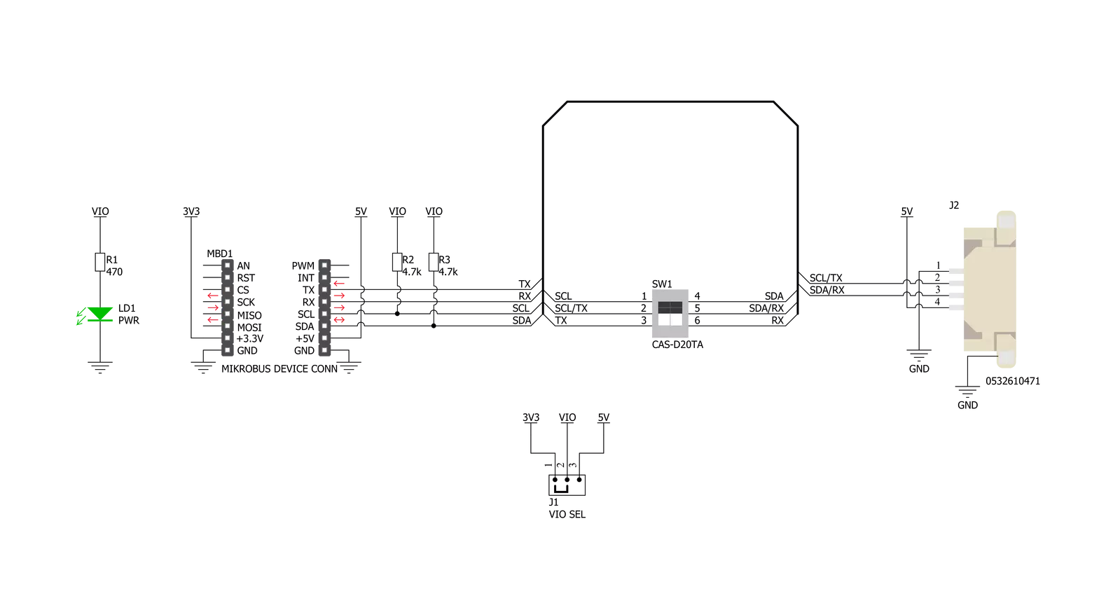
Click board™ Schematic
Step by step
Project assembly
Start by selecting your development board and Click board™. Begin with the Nucleo-64 with STM32F091RC MCU as your development board.


Track your results in real time
Application Output
1. Application Output - In Debug mode, the 'Application Output' window enables real-time data monitoring, offering direct insight into execution results. Ensure proper data display by configuring the environment correctly using the provided tutorial.

2. UART Terminal - Use the UART Terminal to monitor data transmission via a USB to UART converter, allowing direct communication between the Click board™ and your development system. Configure the baud rate and other serial settings according to your project's requirements to ensure proper functionality. For step-by-step setup instructions, refer to the provided tutorial.

3. Plot Output - The Plot feature offers a powerful way to visualize real-time sensor data, enabling trend analysis, debugging, and comparison of multiple data points. To set it up correctly, follow the provided tutorial, which includes a step-by-step example of using the Plot feature to display Click board™ readings. To use the Plot feature in your code, use the function: plot(*insert_graph_name*, variable_name);. This is a general format, and it is up to the user to replace 'insert_graph_name' with the actual graph name and 'variable_name' with the parameter to be displayed.

Software Support
Library Description
This library contains API for TFmini Click driver.
Key functions:
tfmini_get_firmware_version- This function reads the sensor firmware versiontfmini_get_measurement- This function reads the output data frame and obtains the distance, strength and temperature values from ittfmini_send_frame- This function sends a command frame to the sensor
Open Source
Code example
The complete application code and a ready-to-use project are available through the NECTO Studio Package Manager for direct installation in the NECTO Studio. The application code can also be found on the MIKROE GitHub account.
/*!
 * @file main.c
 * @brief TFmini Click Example.
 *
 * # Description
 * This example demonstrates the use of TFmini click board by reading the measurements
 * from the attached TFmini-S or TFmini Plus sensors.
 *
 * The demo application is composed of two sections :
 *
 * ## Application Init
 * Initializes the driver and the click board, and reads the firmware version of the attached sensor.
 *
 * ## Application Task
 * Reads the target distance, signal strength and the internal sensor temperature every 100ms approximately,
 * and displays the results on the USB UART.
 *
 * @author Stefan Filipovic
 *
 */

#include "board.h"
#include "log.h"
#include "tfmini.h"

static tfmini_t tfmini;
static log_t logger;

void application_init ( void )
{
    log_cfg_t log_cfg;        /**< Logger config object. */
    tfmini_cfg_t tfmini_cfg;  /**< Click config object. */

    /**
     * Logger initialization.
     * Default baud rate: 115200
     * Default log level: LOG_LEVEL_DEBUG
     * @note If USB_UART_RX and USB_UART_TX
     * are defined as HAL_PIN_NC, you will
     * need to define them manually for log to work.
     * See @b LOG_MAP_USB_UART macro definition for detailed explanation.
     */
    LOG_MAP_USB_UART( log_cfg );
    log_init( &logger, &log_cfg );
    log_info( &logger, " Application Init " );

    // Click initialization.
    tfmini_cfg_setup( &tfmini_cfg );
    TFMINI_MAP_MIKROBUS( tfmini_cfg, MIKROBUS_1 );
    tfmini_drv_interface_selection ( &tfmini_cfg, TFMINI_DRV_SEL_UART );
    if ( TFMINI_OK != tfmini_init( &tfmini, &tfmini_cfg ) )
    {
        log_error( &logger, " Communication init." );
        for ( ; ; );
    }

    if ( TFMINI_OK != tfmini_default_cfg ( &tfmini ) )
    {
        log_error( &logger, " Default configuration." );
        for ( ; ; );
    }

    uint32_t fw_version = 0;
    if ( TFMINI_OK == tfmini_get_firmware_version ( &tfmini, &fw_version ) )
    {
        log_printf( &logger, " FW Version: 0x%.6LX\r\n", fw_version );
    }
    Delay_ms ( 1000 );

    log_info( &logger, " Application Task " );
}

void application_task ( void )
{
    int16_t distance = 0, strength = 0;
    float temperature = 0;
    if ( TFMINI_OK == tfmini_get_measurement ( &tfmini, &distance, &strength, &temperature ) )
    {
        log_printf( &logger, " Target distance: %d cm\r\n", distance );
        log_printf( &logger, " Signal strength: %d\r\n", strength );
        log_printf( &logger, " Sensor temperature: %.2f C\r\n\n", temperature );
    }
}

int main ( void )
{
    /* Do not remove this line or clock might not be set correctly. */
    #ifdef PREINIT_SUPPORTED
    preinit();
    #endif

    application_init( );

    for ( ; ; )
    {
        application_task( );
    }

    return 0;
}

// ------------------------------------------------------------------------ END