Transform raw ultrasonic data into actionable insights with TUSS4470 and STM32F091RC
Echos transformed: Elevate your ultrasonic experience
Published Feb 26, 2024
Click board™
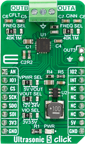
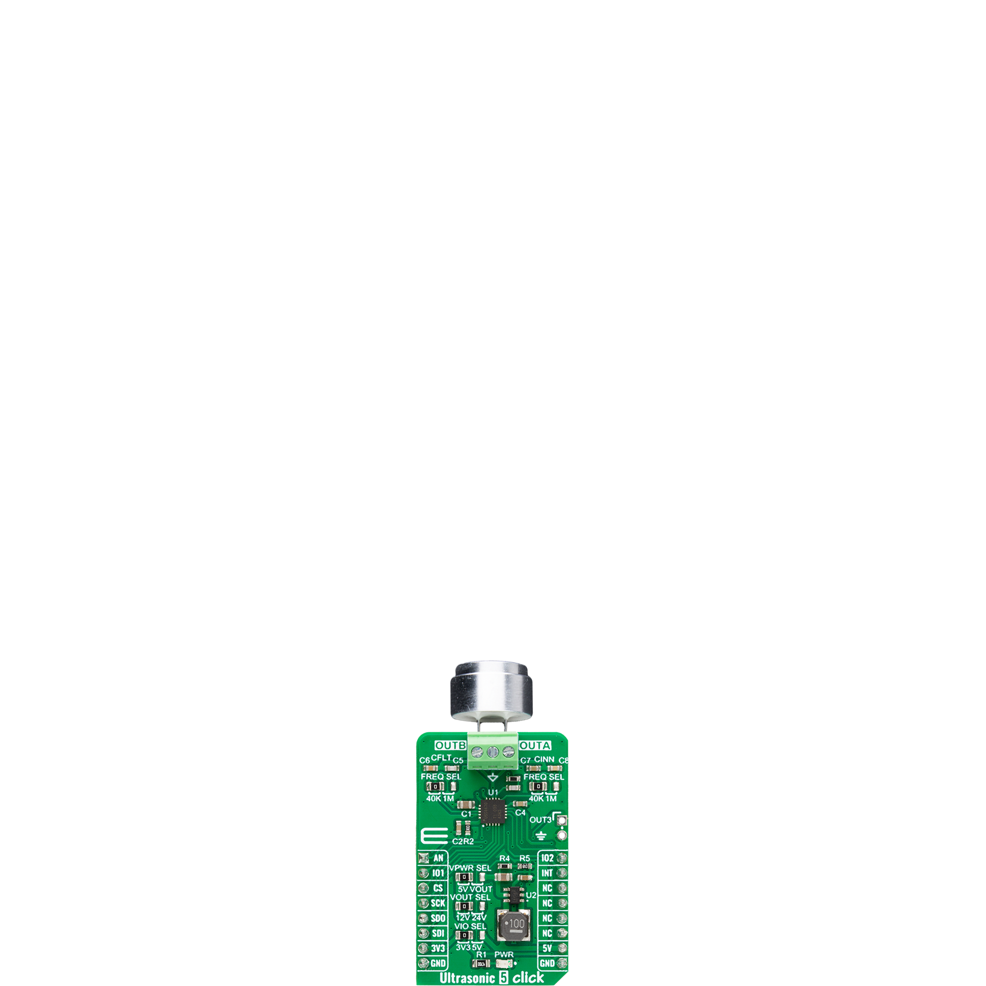
Ultrasonic 5 Click
Dev. board
Nucleo-64 with STM32F091RC MCU
Compiler
NECTO Studio
MCU
STM32F091RC
Unlock the true potential of your ultrasonic sensor with our purpose-built circuits, engineered to extract maximum precision from every pulse and revolutionize your sensing capabilities.
A
A
Hardware Overview
How does it work?
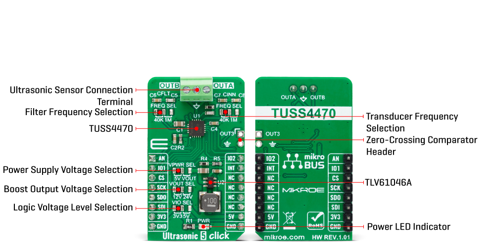
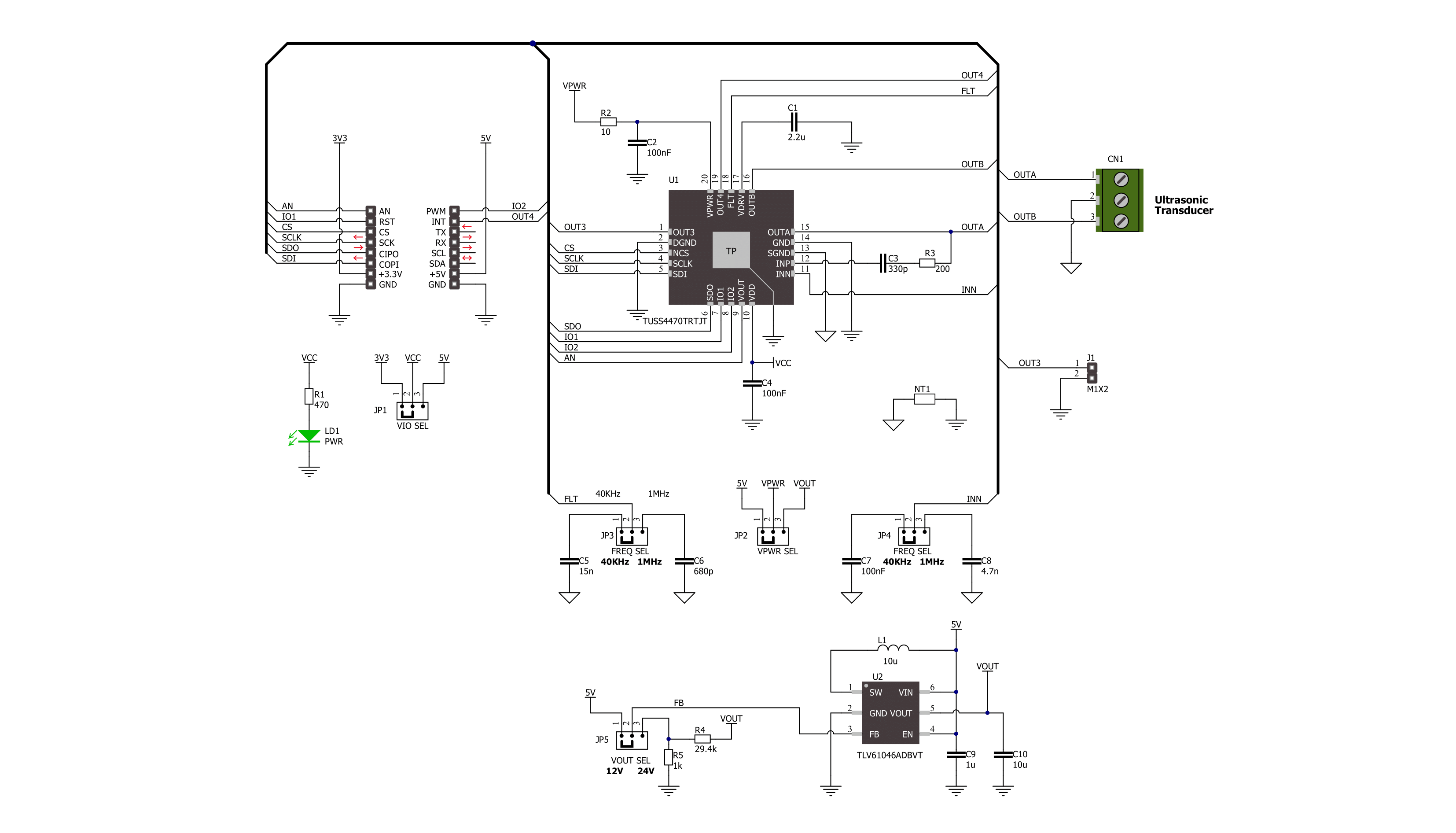
Ultrasonic 5 Click is based on the TUSS4470, a transformer-drive ultrasonic sensor IC with a logarithmic amplifier from Texas Instruments. This highly integrated driver and receiver IC is designed especially for ultrasonic transducers operating in a range of 40KHz up to 1MHz, with pre-driver mode. It has three configurable drive stages: a direct drive using an internal H-bridge for transducer excitation, a pre-driver configuration to use an internal H-bridge to drive external FETs for the higher current drive, and configurable burst patterns over the SPI interface. Also, it has a configurable bandpass filter, wide-band logarithmic amplifier, and first-stage adjustable low-noise amplifier. The cut-off frequency of the low-pass filter can be set over the left frequency selection FREQ SEL jumper with options 40K and 1M, where the 40K(Hz) is set by default. The negative transducer receive path has a frequency selection FREQ SEL jumper on the right side with the same values as the left FREQ SEL jumper. It is also set to 40K as default. It is possible to select some other frequency for both sides by replacing the CINN capacitors (C7, C8) and the CFLT capacitors (C5, C6). Users can choose a burst
pattern from an integrated pulse generator to feed the output driver. There are 4 IO_MODEs that supply the desired frequency through an external clock. This enables you to supply a highly precise clock calibrated to the center frequency of the transducer to enable the highest sound pressure level generation. Ultrasonic 5 Click has a 3-pin terminal (OUTB, GND, OUTA) to connect with the ultrasonic sensor (one UTR-1440K ultrasonic sensor comes with the board). The UTR-1440K ultrasonic sensor comes in an aluminum housing, and its terminal material is tin-plated copper. Its echo sensitivity is ≥200 millivolts. In addition, a zero-crossing signal output (OUT3 header) can be used to validate the frequency of the received echo signal to provide robustness against interference from other signals. It is derived from a row amplified input signal from a particular stage as it is demodulated in the log amp block. The ultrasonic sensor can work on different voltages. Over the VPWR SEL jumper, you can power the transformer-drive IC and the ultrasonic sensor itself with 5V or higher voltages by setting the VOUT option. The 5V from the mikroBUS™ socket power rail is set by default. If you want to use 12V
or 24V to power the sensor and the IC, you must set the VOUT option and choose an appropriate voltage over the VOUT SEL just below (12V is set by default). The TLV61046A, an output voltage boost converter with a power diode and isolation switch from Texas Instruments, provides the 12V and 24V voltages. Ultrasonic 5 Click uses a standard 4-Wire SPI interface to communicate with the host MCU and provide full-duplex communication. The demodulated echo analog output of the IC is available on the AN pin. The echo interrupt signal is available on the INT pin, which goes HIGH logic when the signal on the demodulated echo analog output pin crosses a defined threshold. The configurable burst patterns can be chosen over the IO1 and IO2 pins. This Click board™ can operate with either 3.3V or 5V logic voltage levels selected via the VIO SEL jumper. This way, both 3.3V and 5V capable MCUs can use the communication lines properly. Also, this Click board™ comes equipped with a library containing easy-to-use functions and an example code that can be used as a reference for further development.
Features overview
Development board
Nucleo-64 with STM32F091RC MCU offers a cost-effective and adaptable platform for developers to explore new ideas and prototype their designs. This board harnesses the versatility of the STM32 microcontroller, enabling users to select the optimal balance of performance and power consumption for their projects. It accommodates the STM32 microcontroller in the LQFP64 package and includes essential components such as a user LED, which doubles as an ARDUINO® signal, alongside user and reset push-buttons, and a 32.768kHz crystal oscillator for precise timing operations. Designed with expansion and flexibility in mind, the Nucleo-64 board features an ARDUINO® Uno V3 expansion connector and ST morpho extension pin
headers, granting complete access to the STM32's I/Os for comprehensive project integration. Power supply options are adaptable, supporting ST-LINK USB VBUS or external power sources, ensuring adaptability in various development environments. The board also has an on-board ST-LINK debugger/programmer with USB re-enumeration capability, simplifying the programming and debugging process. Moreover, the board is designed to simplify advanced development with its external SMPS for efficient Vcore logic supply, support for USB Device full speed or USB SNK/UFP full speed, and built-in cryptographic features, enhancing both the power efficiency and security of projects. Additional connectivity is
provided through dedicated connectors for external SMPS experimentation, a USB connector for the ST-LINK, and a MIPI® debug connector, expanding the possibilities for hardware interfacing and experimentation. Developers will find extensive support through comprehensive free software libraries and examples, courtesy of the STM32Cube MCU Package. This, combined with compatibility with a wide array of Integrated Development Environments (IDEs), including IAR Embedded Workbench®, MDK-ARM, and STM32CubeIDE, ensures a smooth and efficient development experience, allowing users to fully leverage the capabilities of the Nucleo-64 board in their projects.

Microcontroller Overview
MCU Card / MCU

Architecture
ARM Cortex-M0
MCU Memory (KB)
256
Silicon Vendor
STMicroelectronics
Pin count
64
RAM (Bytes)
32768
You complete me!
Accessories
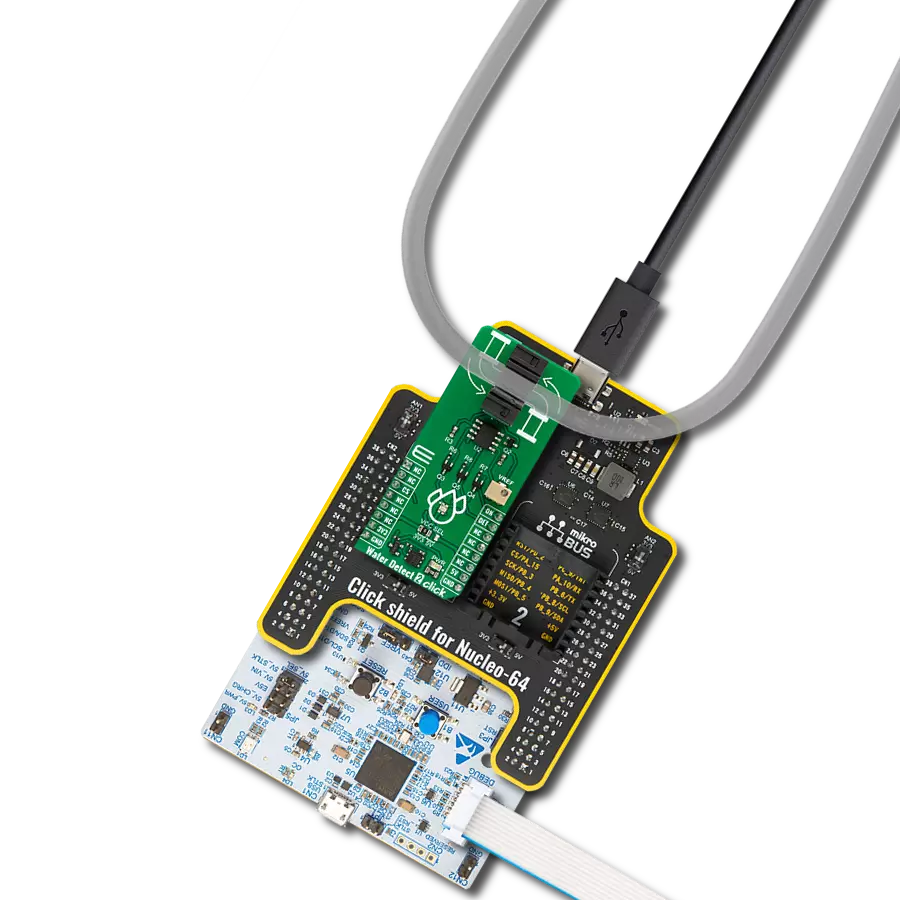
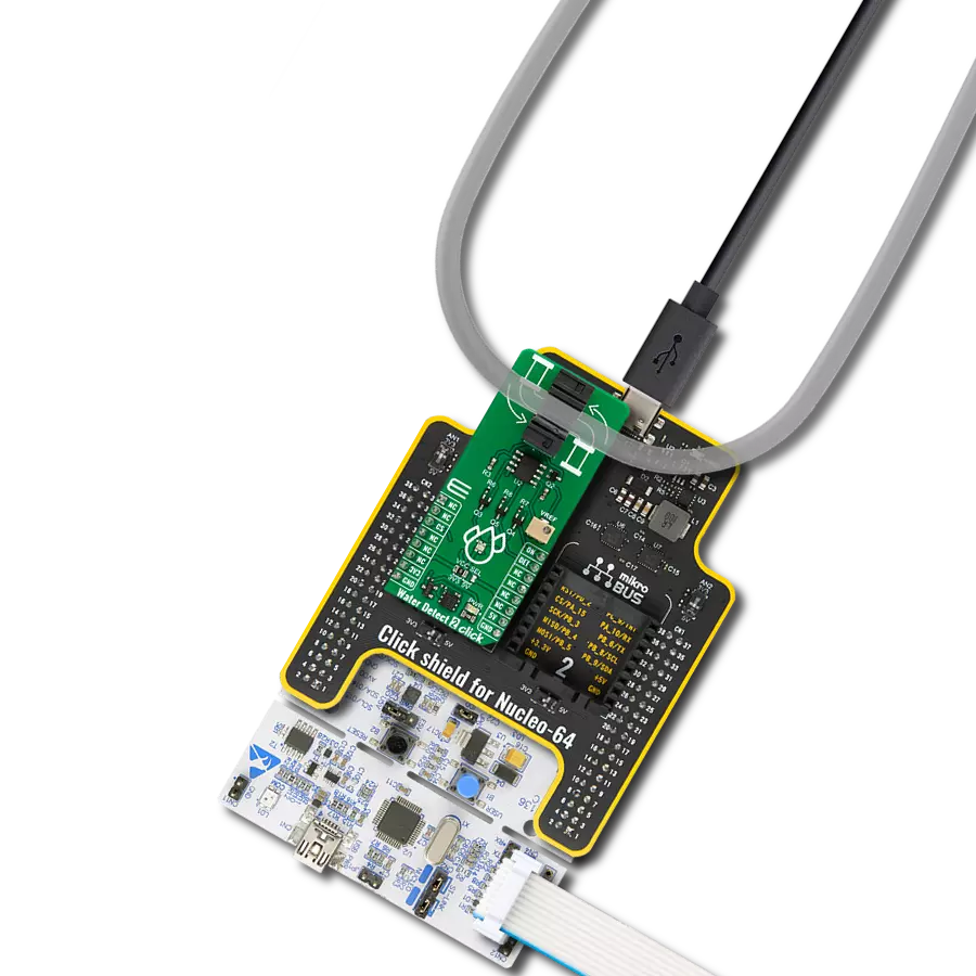
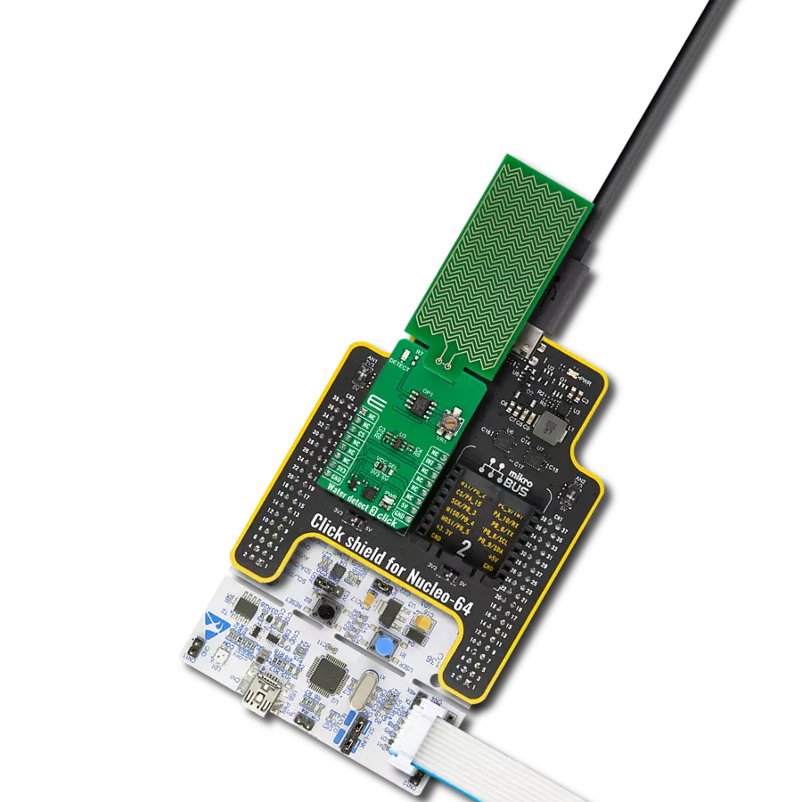
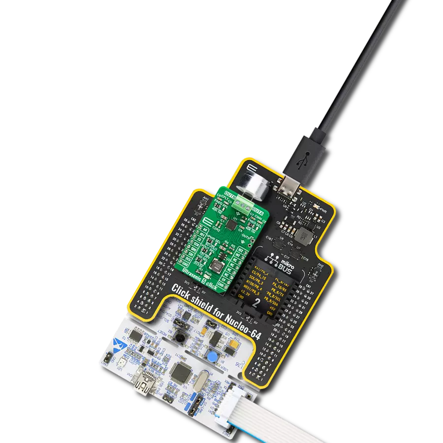
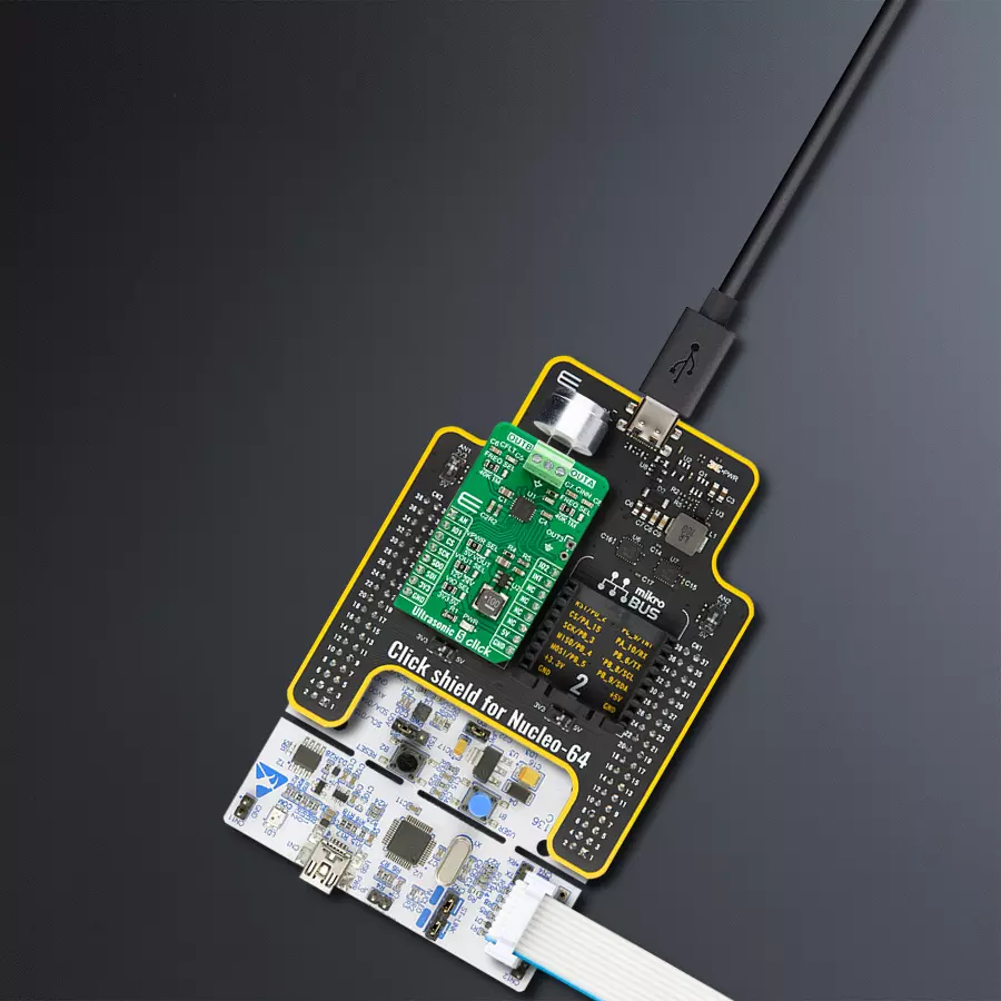
Click Shield for Nucleo-64 comes equipped with two proprietary mikroBUS™ sockets, allowing all the Click board™ devices to be interfaced with the STM32 Nucleo-64 board with no effort. This way, Mikroe allows its users to add any functionality from our ever-growing range of Click boards™, such as WiFi, GSM, GPS, Bluetooth, ZigBee, environmental sensors, LEDs, speech recognition, motor control, movement sensors, and many more. More than 1537 Click boards™, which can be stacked and integrated, are at your disposal. The STM32 Nucleo-64 boards are based on the microcontrollers in 64-pin packages, a 32-bit MCU with an ARM Cortex M4 processor operating at 84MHz, 512Kb Flash, and 96KB SRAM, divided into two regions where the top section represents the ST-Link/V2 debugger and programmer while the bottom section of the board is an actual development board. These boards are controlled and powered conveniently through a USB connection to program and efficiently debug the Nucleo-64 board out of the box, with an additional USB cable connected to the USB mini port on the board. Most of the STM32 microcontroller pins are brought to the IO pins on the left and right edge of the board, which are then connected to two existing mikroBUS™ sockets. This Click Shield also has several switches that perform functions such as selecting the logic levels of analog signals on mikroBUS™ sockets and selecting logic voltage levels of the mikroBUS™ sockets themselves. Besides, the user is offered the possibility of using any Click board™ with the help of existing bidirectional level-shifting voltage translators, regardless of whether the Click board™ operates at a 3.3V or 5V logic voltage level. Once you connect the STM32 Nucleo-64 board with our Click Shield for Nucleo-64, you can access hundreds of Click boards™, working with 3.3V or 5V logic voltage levels.

Used MCU Pins
mikroBUS™ mapper
Take a closer look
Click board™ Schematic
Step by step
Project assembly
Start by selecting your development board and Click board™. Begin with the Nucleo-64 with STM32F091RC MCU as your development board.


Track your results in real time
Application Output
1. Application Output - In Debug mode, the 'Application Output' window enables real-time data monitoring, offering direct insight into execution results. Ensure proper data display by configuring the environment correctly using the provided tutorial.

2. UART Terminal - Use the UART Terminal to monitor data transmission via a USB to UART converter, allowing direct communication between the Click board™ and your development system. Configure the baud rate and other serial settings according to your project's requirements to ensure proper functionality. For step-by-step setup instructions, refer to the provided tutorial.

3. Plot Output - The Plot feature offers a powerful way to visualize real-time sensor data, enabling trend analysis, debugging, and comparison of multiple data points. To set it up correctly, follow the provided tutorial, which includes a step-by-step example of using the Plot feature to display Click board™ readings. To use the Plot feature in your code, use the function: plot(*insert_graph_name*, variable_name);. This is a general format, and it is up to the user to replace 'insert_graph_name' with the actual graph name and 'variable_name' with the parameter to be displayed.

Software Support
Library Description
This library contains API for Ultrasonic 5 Click driver.
Key functions:
ultrasonic5_clear_io1_pin- This function clears the IO1 pin to low logic state.ultrasonic5_pwm_start- This function starts the PWM module output.ultrasonic5_read_an_pin_voltage- This function reads results of AD conversion of the AN pin and converts them to proportional voltage level.
Open Source
Code example
The complete application code and a ready-to-use project are available through the NECTO Studio Package Manager for direct installation in the NECTO Studio. The application code can also be found on the MIKROE GitHub account.
/*!
 * @file main.c
 * @brief Ultrasonic 5 Click example
 *
 * # Description
 * This example demonstrates the use of Ultrasonic 5 Click board by reading
 * the measurements from the connected ultrasonic sensor and displaying it
 * on a Serial Plot.
 *
 * The demo application is composed of two sections :
 *
 * ## Application Init
 * Initializes the driver and performs the Click default configuration.
 *
 * ## Application Task
 * Performs a burst generation which starts the measurement and then reads the next
 * 200 ADC samples and displays the results on the USB UART (SerialPlot).
 *
 * @note
 * In order to get valid measuremets a proper ultrasonic sensor must be connected to OUTA and OUTB.
 * We have used an UTR-1440K-TT-R sensor for the test. We recommend using the SerialPlot tool
 * for data visualizing. Refer to the datasheet "Application Curves" section in order to check
 * and compare the results from the plotter.
 *
 * @author Stefan Filipovic
 *
 */

#include "board.h"
#include "log.h"
#include "ultrasonic5.h"

static ultrasonic5_t ultrasonic5;
static log_t logger;

void application_init ( void )
{
    log_cfg_t log_cfg;  /**< Logger config object. */
    ultrasonic5_cfg_t ultrasonic5_cfg;  /**< Click config object. */

    /**
     * Logger initialization.
     * Default baud rate: 115200
     * Default log level: LOG_LEVEL_DEBUG
     * @note If USB_UART_RX and USB_UART_TX
     * are defined as HAL_PIN_NC, you will
     * need to define them manually for log to work.
     * See @b LOG_MAP_USB_UART macro definition for detailed explanation.
     */
    LOG_MAP_USB_UART( log_cfg );
    log_init( &logger, &log_cfg );
    log_info( &logger, " Application Init " );

    // Click initialization.
    ultrasonic5_cfg_setup( &ultrasonic5_cfg );
    ULTRASONIC5_MAP_MIKROBUS( ultrasonic5_cfg, MIKROBUS_1 );
    if ( ULTRASONIC5_OK != ultrasonic5_init( &ultrasonic5, &ultrasonic5_cfg ) )
    {
        log_error( &logger, " Communication init." );
        for ( ; ; );
    }

    if ( ULTRASONIC5_OK != ultrasonic5_default_cfg ( &ultrasonic5 ) )
    {
        log_error( &logger, " Default configuration." );
        for ( ; ; );
    }

    log_info( &logger, " Application Task " );
}

void application_task ( void )
{
    float voltage = 0;
    // Burst generation / Start measurement
    ultrasonic5_set_duty_cycle ( &ultrasonic5, ULTRASONIC5_DEF_DYTY );
    ultrasonic5_pwm_start( &ultrasonic5 );
    ultrasonic5_clear_io1_pin ( &ultrasonic5 );
    Delay_500us ( );
    ultrasonic5_set_io1_pin ( &ultrasonic5 );
    ultrasonic5_pwm_stop( &ultrasonic5 );
    // Read and log the next 200 ADC samples which we will plot on a Serial Plotter
    for ( uint16_t cnt = 0; cnt < 200; cnt++ )
    {
        if ( ULTRASONIC5_OK == ultrasonic5_read_an_pin_voltage ( &ultrasonic5, &voltage ) )
        {
            log_printf( &logger, "%.3f\r\n", voltage );
        }
    }
}

int main ( void )
{
    /* Do not remove this line or clock might not be set correctly. */
    #ifdef PREINIT_SUPPORTED
    preinit();
    #endif

    application_init( );

    for ( ; ; )
    {
        application_task( );
    }

    return 0;
}

// ------------------------------------------------------------------------ END