Experience the future of seamless charging and data synchronization with AP33772 and STM32F091RC
Versatile power delivery for a truly connected lifestyle

Published Feb 26, 2024
Click board™
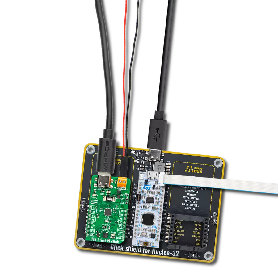
USB-C Sink 2 Click
Dev. board
Nucleo-64 with STM32F091RC MCU
Compiler
NECTO Studio
MCU
STM32F091RC
Transform the way you connect and charge with our cutting-edge USB-C sink solution, delivering reliability and performance beyond expectations
A
A
Hardware Overview
How does it work?
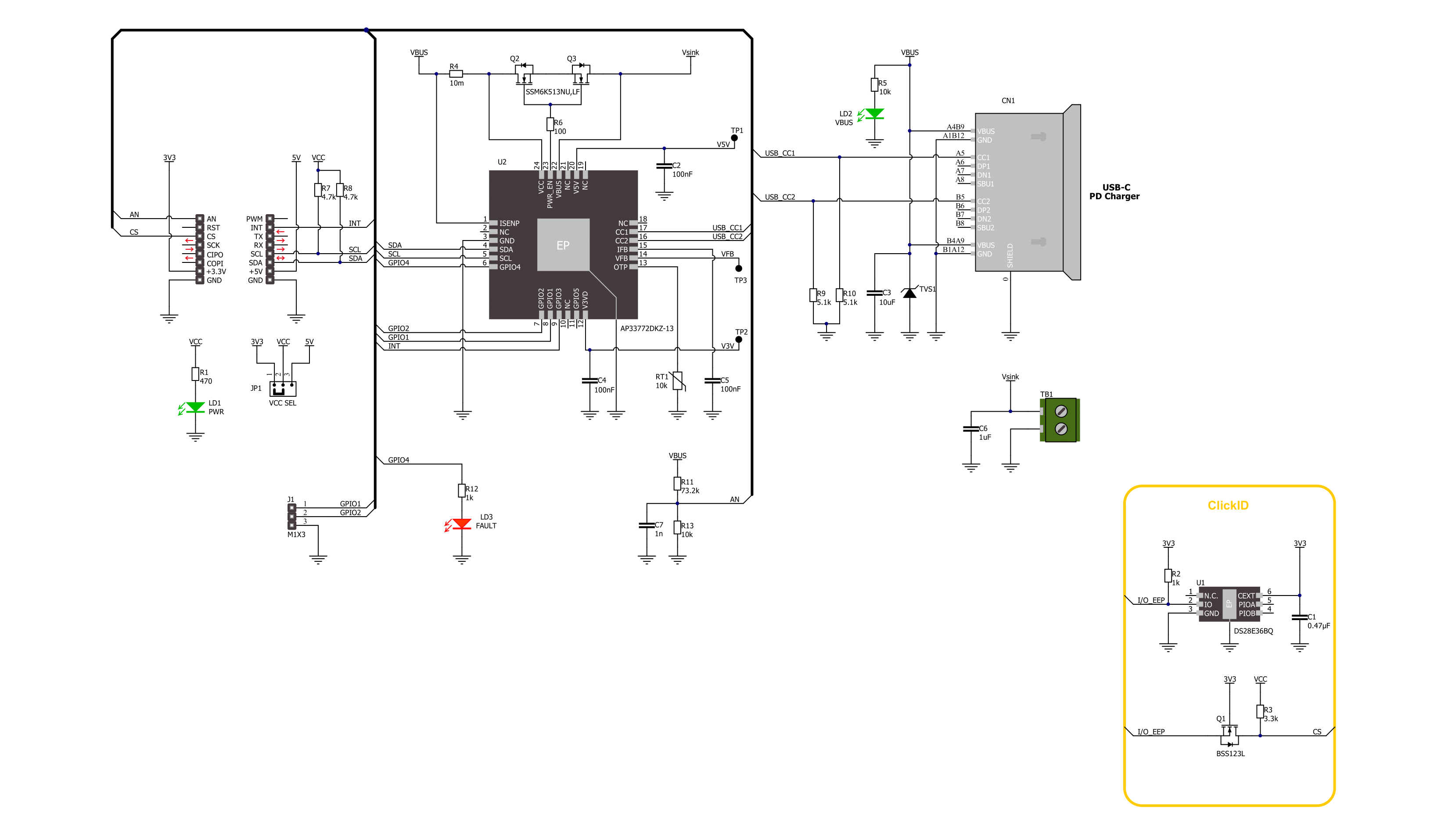
USB-C Sink 2 Click is based on the AP33772, a high-performance USB PD sink controller from Diodes Incorporated. The host MCU can control the PPS with 20mV/step voltage and 50mA/step current. The PD controller supports overtemperature protection (OTP), OVP with auto-restart, OCP with auto-restart, one-time programming (OTP), power-saving mode, and a system monitor and control status register. For OTP, this Click board™ comes with an NTC temperature sensor, with selectable temperature points (25°C, 50°C, 75°C, 100°C) as a temperature threshold. The onboard FAULT LED serves as a visual presentation of the negotiation mismatch. The Multi-time programming (MTP) is reserved for future configuration. This USB Type-C power delivery sink controller requires power from a
standard USB source adapter, in our case from the USB connector labeled USB-C PD-IN, and then delivers power to connected devices on the VSINK connector. A pair of MOSFETs stands between the USB and VSINK terminal, according to the AP33772 driver for N-MOS VBUS power switch support. The PD controller can control the external NMOS switch ON or OFF (all control is done via the I2C interface). The USB C connector acts as a PD-IN discharge path terminal with a USB Type-C configuration channels 1 and 2. The presence of the power supply on the USB C is indicated over the VBUS LED. The AP33772 is equipped with several GPIOs. The user-configurable GPIO1 and GPIO2 are available on the side header labeled GP1 and GP2, with additional GND. Also, this Click board™ has several test pads for testing
purposes. The 5V and 3.3V LDO voltage output can be measured over the V5V and V3V pads and voltage feedback over the VFB pad. USB-C Sink 2 Click uses a standard 2-Wire I2C interface to communicate with the host MCU. The interrupts from AP33772 can be monitored over the INT pin. One of the additional features of the USB-C Sink 2 Click is the ability to track the VBUS voltage over the AN pin of the mikroBUS™ socket. This Click board™ can operate with either 3.3V or 5V logic voltage levels selected via the VCC SEL jumper. This way, both 3.3V and 5V capable MCUs can use the communication lines properly. Also, this Click board™ comes equipped with a library containing easy-to-use functions and an example code that can be used as a reference for further development.

Features overview
Development board
Nucleo-64 with STM32F091RC MCU offers a cost-effective and adaptable platform for developers to explore new ideas and prototype their designs. This board harnesses the versatility of the STM32 microcontroller, enabling users to select the optimal balance of performance and power consumption for their projects. It accommodates the STM32 microcontroller in the LQFP64 package and includes essential components such as a user LED, which doubles as an ARDUINO® signal, alongside user and reset push-buttons, and a 32.768kHz crystal oscillator for precise timing operations. Designed with expansion and flexibility in mind, the Nucleo-64 board features an ARDUINO® Uno V3 expansion connector and ST morpho extension pin
headers, granting complete access to the STM32's I/Os for comprehensive project integration. Power supply options are adaptable, supporting ST-LINK USB VBUS or external power sources, ensuring adaptability in various development environments. The board also has an on-board ST-LINK debugger/programmer with USB re-enumeration capability, simplifying the programming and debugging process. Moreover, the board is designed to simplify advanced development with its external SMPS for efficient Vcore logic supply, support for USB Device full speed or USB SNK/UFP full speed, and built-in cryptographic features, enhancing both the power efficiency and security of projects. Additional connectivity is
provided through dedicated connectors for external SMPS experimentation, a USB connector for the ST-LINK, and a MIPI® debug connector, expanding the possibilities for hardware interfacing and experimentation. Developers will find extensive support through comprehensive free software libraries and examples, courtesy of the STM32Cube MCU Package. This, combined with compatibility with a wide array of Integrated Development Environments (IDEs), including IAR Embedded Workbench®, MDK-ARM, and STM32CubeIDE, ensures a smooth and efficient development experience, allowing users to fully leverage the capabilities of the Nucleo-64 board in their projects.

Microcontroller Overview
MCU Card / MCU

Architecture
ARM Cortex-M0
MCU Memory (KB)
256
Silicon Vendor
STMicroelectronics
Pin count
64
RAM (Bytes)
32768
You complete me!
Accessories
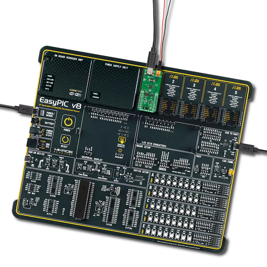
Click Shield for Nucleo-64 comes equipped with two proprietary mikroBUS™ sockets, allowing all the Click board™ devices to be interfaced with the STM32 Nucleo-64 board with no effort. This way, Mikroe allows its users to add any functionality from our ever-growing range of Click boards™, such as WiFi, GSM, GPS, Bluetooth, ZigBee, environmental sensors, LEDs, speech recognition, motor control, movement sensors, and many more. More than 1537 Click boards™, which can be stacked and integrated, are at your disposal. The STM32 Nucleo-64 boards are based on the microcontrollers in 64-pin packages, a 32-bit MCU with an ARM Cortex M4 processor operating at 84MHz, 512Kb Flash, and 96KB SRAM, divided into two regions where the top section represents the ST-Link/V2 debugger and programmer while the bottom section of the board is an actual development board. These boards are controlled and powered conveniently through a USB connection to program and efficiently debug the Nucleo-64 board out of the box, with an additional USB cable connected to the USB mini port on the board. Most of the STM32 microcontroller pins are brought to the IO pins on the left and right edge of the board, which are then connected to two existing mikroBUS™ sockets. This Click Shield also has several switches that perform functions such as selecting the logic levels of analog signals on mikroBUS™ sockets and selecting logic voltage levels of the mikroBUS™ sockets themselves. Besides, the user is offered the possibility of using any Click board™ with the help of existing bidirectional level-shifting voltage translators, regardless of whether the Click board™ operates at a 3.3V or 5V logic voltage level. Once you connect the STM32 Nucleo-64 board with our Click Shield for Nucleo-64, you can access hundreds of Click boards™, working with 3.3V or 5V logic voltage levels.

Used MCU Pins
mikroBUS™ mapper
Take a closer look
Click board™ Schematic
Step by step
Project assembly
Start by selecting your development board and Click board™. Begin with the Nucleo-64 with STM32F091RC MCU as your development board.


Software Support
Library Description
This library contains API for USB-C Sink 2 Click driver.
Key functions:
usbcsink2_write_rdo- USB-C Sink 2 write the RDO function.usbcsink2_get_pdo_voltage- USB-C Sink 2 get the voltage function.usbcsink2_get_pdo_current- USB-C Sink 2 get the current function.
Open Source
Code example
The complete application code and a ready-to-use project are available through the NECTO Studio Package Manager for direct installation in the NECTO Studio. The application code can also be found on the MIKROE GitHub account.
/*!
* @file main.c
* @brief USB-C Sink 2 Click Example.
*
* # Description
* This example demonstrates the use of the USB-C Sink 2 Click board™
* by setting DC power requests and control for Type-C connector-equipped devices (TCD).
*
* The demo application is composed of two sections :
*
* ## Application Init
* Initializes I2C and ADC modules and log UART.
* After driver initialization the app set default settings.
*
* ## Application Task
* In this example, the app configures Power Data Objects (PDO)
* highest priority profile and requests power from a standard USB PD source adapter.
* After connecting the PD source and USB-C Sink 2 Click with the Type-C cable,
* the app gets the total number of valid PDO's
* and switches all PDO configurations every 10 seconds.
* When the PD source accepts the request, the app displays information about
* VOUT Voltage [mV] and Current [mA] and the temperature [degree Celsius] of the USB-C connector.
*
* @note
* FAULT LED flickering notified of the system status:
* - Charging: Breathing light (2 sec dimming), 1 cycle is 4 sec.
* - Fully charged: Continuously lit Charging current < 500mA.
* - Mismatch: 1s flicker Voltage or power mismatch. Non-PD power source, 1 cycle is 2sec.
* - Fault: 300ms flicker OVP, 1 cycle is 600ms.
*
* @author Nenad Filipovic
*
*/
#include "board.h"
#include "log.h"
#include "usbcsink2.h"
static usbcsink2_t usbcsink2; /**< USB-C Sink 2 Click driver object. */
static log_t logger; /**< Logger object. */
void application_init ( void )
{
log_cfg_t log_cfg; /**< Logger config object. */
usbcsink2_cfg_t usbcsink2_cfg; /**< Click config object. */
/**
* Logger initialization.
* Default baud rate: 115200
* Default log level: LOG_LEVEL_DEBUG
* @note If USB_UART_RX and USB_UART_TX
* are defined as HAL_PIN_NC, you will
* need to define them manually for log to work.
* See @b LOG_MAP_USB_UART macro definition for detailed explanation.
*/
LOG_MAP_USB_UART( log_cfg );
log_init( &logger, &log_cfg );
log_info( &logger, " Application Init " );
// Click initialization.
usbcsink2_cfg_setup( &usbcsink2_cfg );
USBCSINK2_MAP_MIKROBUS( usbcsink2_cfg, MIKROBUS_1 );
err_t init_flag = usbcsink2_init( &usbcsink2, &usbcsink2_cfg );
if ( ( ADC_ERROR == init_flag ) || ( I2C_MASTER_ERROR == init_flag ) )
{
log_error( &logger, " Communication init." );
for ( ; ; );
}
if ( USBCSINK2_ERROR == usbcsink2_default_cfg ( &usbcsink2 ) )
{
log_error( &logger, " Default configuration." );
for ( ; ; );
}
log_info( &logger, " Application Task " );
log_printf( &logger, "---------------------------\r\n" );
Delay_ms ( 100 );
}
void application_task ( void )
{
static float voltage_mv = 0, current_ma = 0;
static uint8_t temperature = 0;
for ( uint8_t pdo_num = 0; pdo_num < usbcsink2.number_of_valid_pdo; pdo_num++ )
{
usbcsink2.pdo_data[ pdo_num * 4 + 3 ] = ( pdo_num + 1 ) << 4;
if ( USBCSINK2_OK == usbcsink2_write_rdo( &usbcsink2, &usbcsink2.pdo_data[ pdo_num * 4 ] ) )
{
log_printf( &logger, " --- PDO[ %d ] ---\r\n", ( uint16_t ) pdo_num );
}
if ( USBCSINK2_OK == usbcsink2_wait_rdo_req_success( &usbcsink2 ) )
{
if ( USBCSINK2_OK == usbcsink2_get_pdo_voltage( &usbcsink2, &voltage_mv ) )
{
log_printf( &logger, " Voltage : %.2f mV\r\n", voltage_mv );
}
if ( USBCSINK2_OK == usbcsink2_get_pdo_current( &usbcsink2, ¤t_ma ) )
{
log_printf( &logger, " Current : %.2f mA\r\n", current_ma );
}
if ( USBCSINK2_OK == usbcsink2_get_temperature( &usbcsink2, &temperature ) )
{
log_printf( &logger, " Temperature : %d C\r\n", ( uint16_t ) temperature );
}
log_printf( &logger, "---------------------------\r\n" );
// 10 seconds delay
Delay_ms ( 1000 );
Delay_ms ( 1000 );
Delay_ms ( 1000 );
Delay_ms ( 1000 );
Delay_ms ( 1000 );
Delay_ms ( 1000 );
Delay_ms ( 1000 );
Delay_ms ( 1000 );
Delay_ms ( 1000 );
Delay_ms ( 1000 );
}
}
}
int main ( void )
{
/* Do not remove this line or clock might not be set correctly. */
#ifdef PREINIT_SUPPORTED
preinit();
#endif
application_init( );
for ( ; ; )
{
application_task( );
}
return 0;
}
// ------------------------------------------------------------------------ END
Additional Support
Resources
Category:USB-C PD