Achieve precise presence sensing and motion detection with TPIS1S1385 and ATmega32
Create secure, smart, and efficient environments
Published Jul 09, 2024
Click board™
Presence Click
Dev. board
EasyAVR v8
Compiler
NECTO Studio
MCU
ATmega32
Our infrared solution is a versatile tool designed to enable precise presence sensing, motion detection, and remote overtemperature protection across various applications
A
A
Hardware Overview
How does it work?
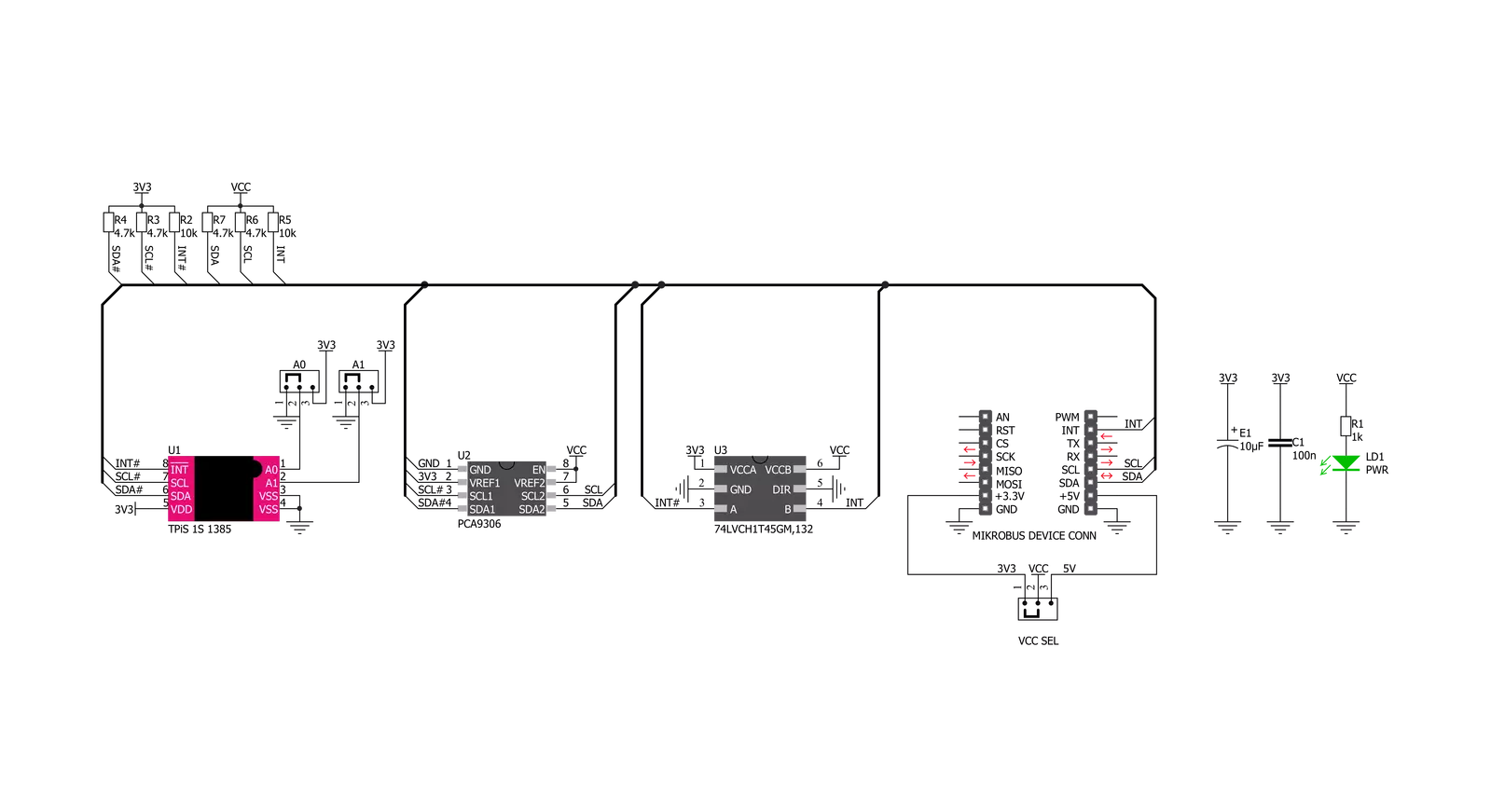
Presence Click is based on the TPiS 1S 1385, a device from CaliPile™ multi-function infrared sensor series, from Excelitas Technologies. Despite its very compact design (4.4 x 2.6 x 1.75 mm2), it features an integrated signal processing ASIC, which allows detection of several different events, common to all the sensors from CaliPile™ series. The TPiS 1S 1385 features near-field motion detection, presence detection, and remote temperature measurement. The infrared light emitted from the object is detected by the thermopile sensor, converted by a highly sensitive 17-bit ADC, and digitally processed to allow event detection. Event detection can be fine-tuned over the I2C interface, by accessing corresponding config registers. The CaliPile™ series sensors can utilize the embedded processing engine to detect several different events, including motion, presence, and temperature shock events. Each of these events is based on measuring the temperature and then comparing it with a value which is taken after a time interval. The device does not consume much power while processing the data; significantly more power is consumed during the sampling intervals. Since the measurement is done in just a few points of time,
not much power is consumed overall. This feature allows using the sensor IC on battery-operated systems. A particularly interesting feature is ambient temperature shock detection. This allows detecting fast changes of the temperature, which can be used to remotely detect overtemperature event in some power installations or similar inaccessible locations. The TPiS 1S 1385 is able to perform data processing. However, the firmware running on the host MCU has to perform some calculations, taking calibration parameters from the EEPROM into account, in order to determine the temperature of the target object. The thermopile sensor reacts to IR light reflection; therefore, some external parameters have to be taken into consideration. More information about these parameters and how to calculate the output can be found in the TPiS 1S 1385 datasheet. The interrupt pin allows the detected event to be reported to the host MCU. This is crucial for wakeup-on-proximity applications. The interrupt will be cleared only after reading the Interrupt Status register. The interrupt pin is an active LOW output, routed to the INT pin of the mikroBUS™. It is pulled to a HIGH logic state by an onboard resistor, when not asserted. After the power on,
the device only responds to the General Call Address, which is 0x00. After it receives a general call, it loads its I2C address which is stored in the EEPROM register. Depending on the most significant bit (MSB) within this register, the states of the two physical pins A0 and A1 will replace the values of the two least significant bits (LSB). Pins A0 and A1 are routed to the SMD jumpers grouped under the ADR SEL label, allowing the developer to select an I2C slave address when more than a single device exists on the I2C bus. The datasheet of the TPiS 1S 1385 illustrates the use of the EEPROM register, along with the A0 and A1 pins. However, the Click board™ is supported by a set of mikroSDK library functions which simplify the use of this IC, along with a demo example which can be used as a reference for a custom design. In addition to TPiS 1S 1385, Presence click features two additional ICs: the PCA9306, and the 74LVCH1T45. The PCA9306 is a bi-directional level shifter for the I2C signals, while the 74LVCH1T45 is a single bit level shifter, used for the INT line. Both ICs are produced by NXP. They allow both 3.3V and 5V MCUs to be interfaced with the Click board™, vastly expanding its usability.


Features overview
Development board
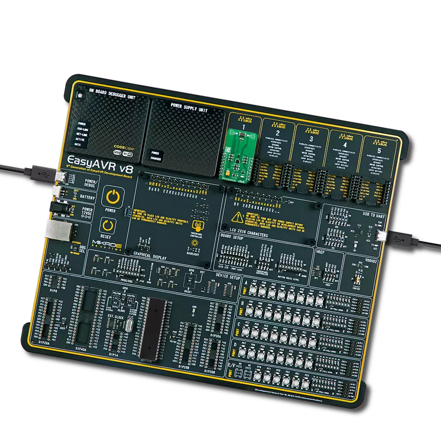
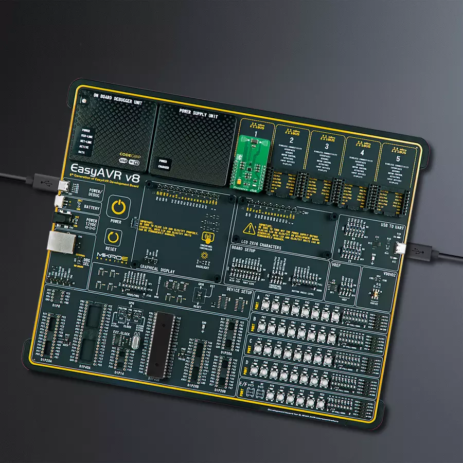
EasyAVR v8 is a development board designed to rapidly develop embedded applications based on 8-bit AVR microcontrollers (MCUs). Redesigned from the ground up, EasyAVR v8 offers a familiar set of standard features, as well as some new and unique features standard for the 8th generation of development boards: programming and debugging over the WiFi network, connectivity provided by USB-C connectors, support for a wide range of different MCUs, and more. The development board is designed so that the developer has everything that might be needed for the application development, following the Swiss Army knife concept: a highly advanced programmer/debugger module, a reliable power supply module, and a USB-UART connectivity option. EasyAVR v8 board offers several different DIP sockets, covering a wide range of 8-bit AVR MCUs, from the smallest
AVR MCU devices with only eight pins, all the way up to 40-pin "giants". The development board supports the well-established mikroBUS™ connectivity standard, offering five mikroBUS™ sockets, allowing access to a huge base of Click boards™. EasyAVR v8 offers two display options, allowing even the basic 8-bit AVR MCU devices to utilize them and display graphical or textual content. One of them is the 1x20 graphical display connector, compatible with the familiar Graphical Liquid Crystal Display (GLCD) based on the KS108 (or compatible) display driver, and EasyTFT board that contains TFT Color Display MI0283QT-9A, which is driven by ILI9341 display controller, capable of showing advanced graphical content. The other option is the 2x16 character LCD module, a four-bit display module with an embedded character-based display controller. It
requires minimal processing power from the host MCU for its operation. There is a wide range of useful interactive options at the disposal: high-quality buttons with selectable press levels, LEDs, pull-up/pulldown DIP switches, and more. All these features are packed on a single development board, which uses innovative manufacturing technologies, delivering a fluid and immersive working experience. The EasyAVR v8 development board is also integral to the MIKROE rapid development ecosystem. Natively supported by the MIKROE Software toolchain, backed up by hundreds of different Click board™ designs with their number growing daily, it covers many different prototyping and development aspects, thus saving precious development time.

Microcontroller Overview
MCU Card / MCU

Architecture
AVR
MCU Memory (KB)
32
Silicon Vendor
Microchip
Pin count
40
RAM (Bytes)
2048
Used MCU Pins
mikroBUS™ mapper
Take a closer look
Click board™ Schematic
Step by step
Project assembly

Start by selecting your development board and Click board™. Begin with the EasyAVR v8 as your development board.


Track your results in real time
Application Output
1. Application Output - In Debug mode, the 'Application Output' window enables real-time data monitoring, offering direct insight into execution results. Ensure proper data display by configuring the environment correctly using the provided tutorial.

2. UART Terminal - Use the UART Terminal to monitor data transmission via a USB to UART converter, allowing direct communication between the Click board™ and your development system. Configure the baud rate and other serial settings according to your project's requirements to ensure proper functionality. For step-by-step setup instructions, refer to the provided tutorial.

3. Plot Output - The Plot feature offers a powerful way to visualize real-time sensor data, enabling trend analysis, debugging, and comparison of multiple data points. To set it up correctly, follow the provided tutorial, which includes a step-by-step example of using the Plot feature to display Click board™ readings. To use the Plot feature in your code, use the function: plot(*insert_graph_name*, variable_name);. This is a general format, and it is up to the user to replace 'insert_graph_name' with the actual graph name and 'variable_name' with the parameter to be displayed.

Software Support
Library Description
This library contains API for Presence Click driver.
Key functions:
presence_ambient_temperature- This function returns ambient temperature in degrees Celsiuspresence_object_temperature- This function returns object temperature.
Open Source
Code example
The complete application code and a ready-to-use project are available through the NECTO Studio Package Manager for direct installation in the NECTO Studio. The application code can also be found on the MIKROE GitHub account.
/*!
 * \file
 * \brief Presence Click example
 *
 * # Description
 * This application enables usage of sensor for motion and presence sensing
 * and measuring of object's and ambient temperature.
 *
 * The demo application is composed of two sections :
 *
 * ## Application Init
 * Initializes driver and performs the Click default configuration.
 *
 * ## Application Task
 * Checks whether a new event (motion, presence or over-temperature) is detected.
 * If there's no event detected it reads the ambient and object temperature and displays
 * the results on the USB UART.
 *
 * \author MikroE Team
 *
 */
// ------------------------------------------------------------------- INCLUDES

#include "board.h"
#include "log.h"
#include "presence.h"

// ------------------------------------------------------------------ VARIABLES

static presence_t presence;
static log_t logger;

// ------------------------------------------------------ APPLICATION FUNCTIONS

void application_init ( void )
{
    log_cfg_t log_cfg;
    presence_cfg_t cfg;

    /**
     * Logger initialization.
     * Default baud rate: 115200
     * Default log level: LOG_LEVEL_DEBUG
     * @note If USB_UART_RX and USB_UART_TX
     * are defined as HAL_PIN_NC, you will
     * need to define them manually for log to work.
     * See @b LOG_MAP_USB_UART macro definition for detailed explanation.
     */
    LOG_MAP_USB_UART( log_cfg );
    log_init( &logger, &log_cfg );
    log_info( &logger, "---- Application Init ----" );

    //  Click initialization.
    presence_cfg_setup( &cfg );
    PRESENCE_MAP_MIKROBUS( cfg, MIKROBUS_1 );
    presence_init( &presence, &cfg );

    if ( PRESENCE_ERROR == presence_default_cfg ( &presence ) )
    {
        log_error( &logger, " Default configuration." );
        for ( ; ; );
    }

    log_info( &logger, " Application Task " );
}

void application_task ( void )
{
    uint8_t int_status = 0;
    uint8_t tp_presence = 0;
    uint8_t tp_motion = 0;
    float t_amb = 0;
    float t_obj = 0;

    if ( PRESENCE_OK == presence_generic_read( &presence, PRESENCE_REG_INTERRUPT_STATUS, &int_status, 1 ) )
    {
        if ( int_status & PRESENCE_INT_MASK1_PRESENCE )
        {
            if ( PRESENCE_OK == presence_generic_read( &presence, PRESENCE_REG_TP_PRESENCE, &tp_presence, 1 ) )
            {
                log_info( &logger, "Presence detected! Level: %u", ( uint16_t ) tp_presence );
            }
        }
        else if ( int_status & PRESENCE_INT_MASK1_MOTION )
        {
            if ( PRESENCE_OK == presence_generic_read( &presence, PRESENCE_REG_TP_MOTION, &tp_motion, 1 ) )
            {
                log_info( &logger, "Motion detected! Level: %u", ( uint16_t ) tp_motion );
            }
        }
        else if ( int_status & PRESENCE_INT_MASK1_TP_OT )
        {
            log_info( &logger, "Temp threshold exceeded!" );
        }
        else
        {
            if ( PRESENCE_OK == presence_ambient_temperature( &presence, &t_amb ) )
            {
                log_printf( &logger, "Ambient temperature: %.2f degC\r\n", t_amb );
            }
            if ( PRESENCE_OK == presence_object_temperature( &presence, &t_obj ) )
            {
                log_printf( &logger, "Object temperature: %.2f degC\r\n\n", t_obj );
            }
        }
    }
    Delay_ms ( 1000 );
}

int main ( void )
{
    /* Do not remove this line or clock might not be set correctly. */
    #ifdef PREINIT_SUPPORTED
    preinit();
    #endif

    application_init( );

    for ( ; ; )
    {
        application_task( );
    }

    return 0;
}

// ------------------------------------------------------------------------ END
Additional Support
Resources
Category:Miscellaneous


