Build a reliable serial communication system with SP3221E and ATmega644
The ultimate wingman for your communication needs
Published Jul 09, 2024
Click board™
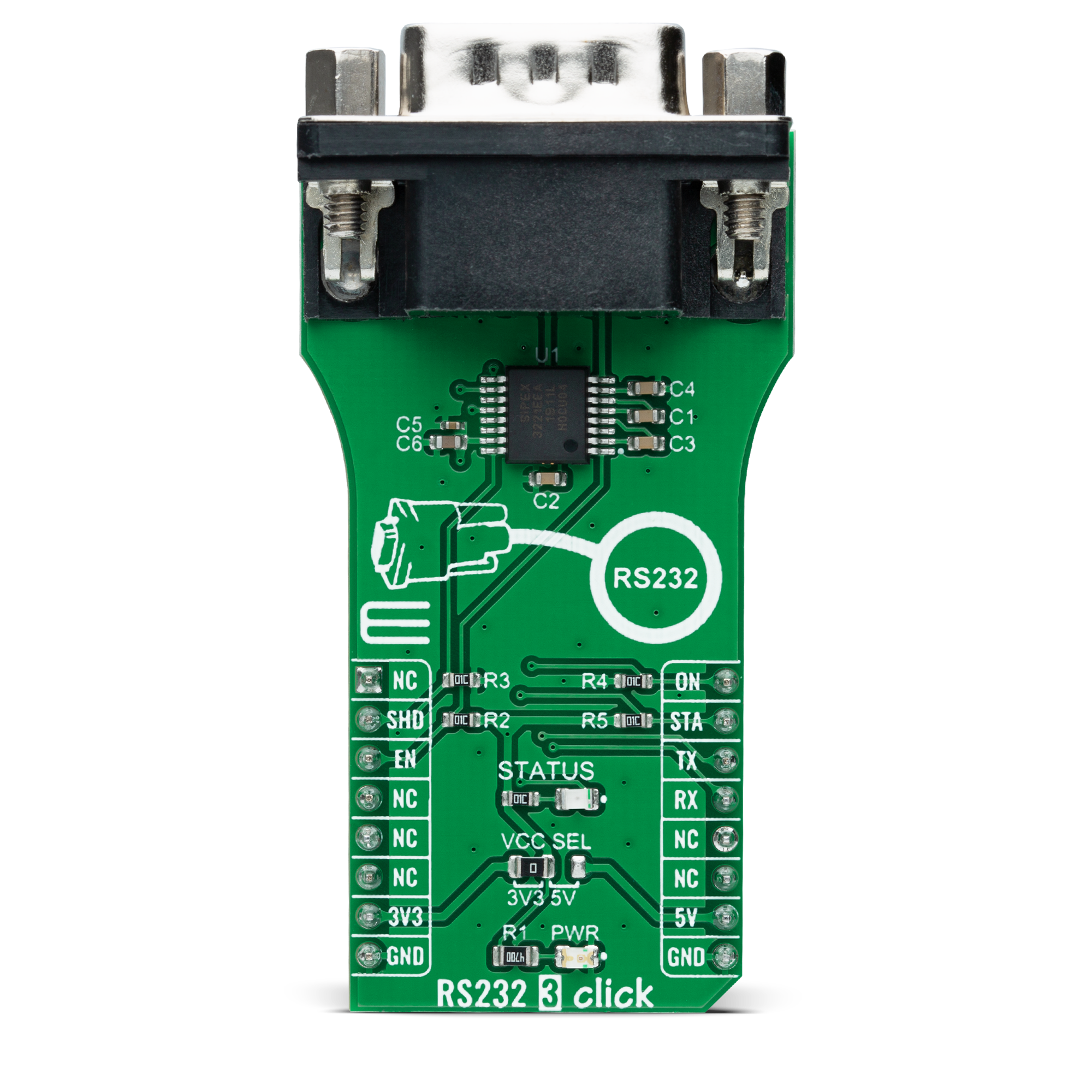
RS232 3 Click
Dev. board
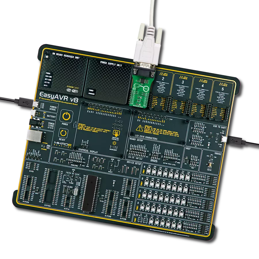
EasyAVR v8
Compiler
NECTO Studio
MCU
ATmega644
Maximize your serial communication with the reliable and low-power RS232 transceiver
A
A
Hardware Overview
How does it work?
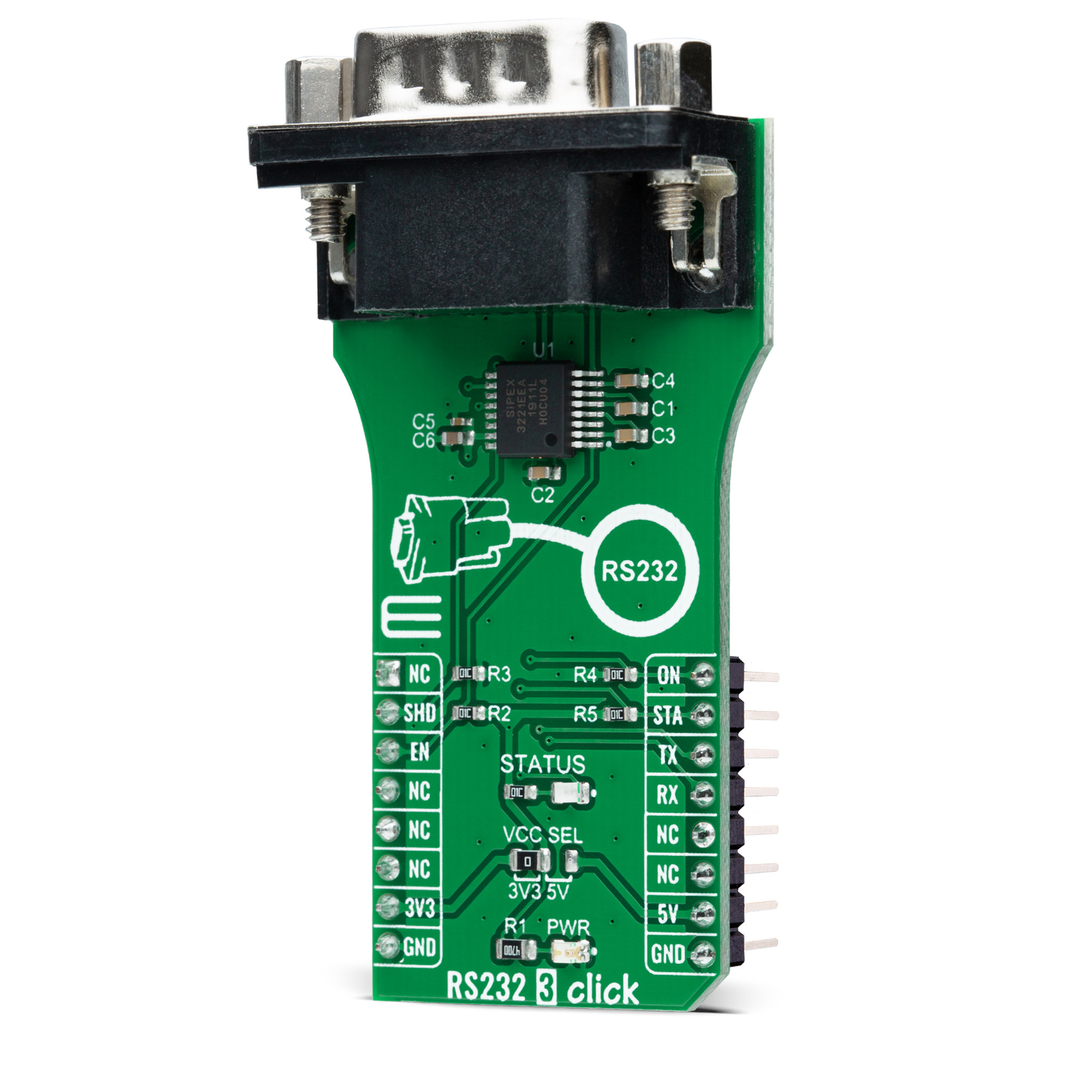
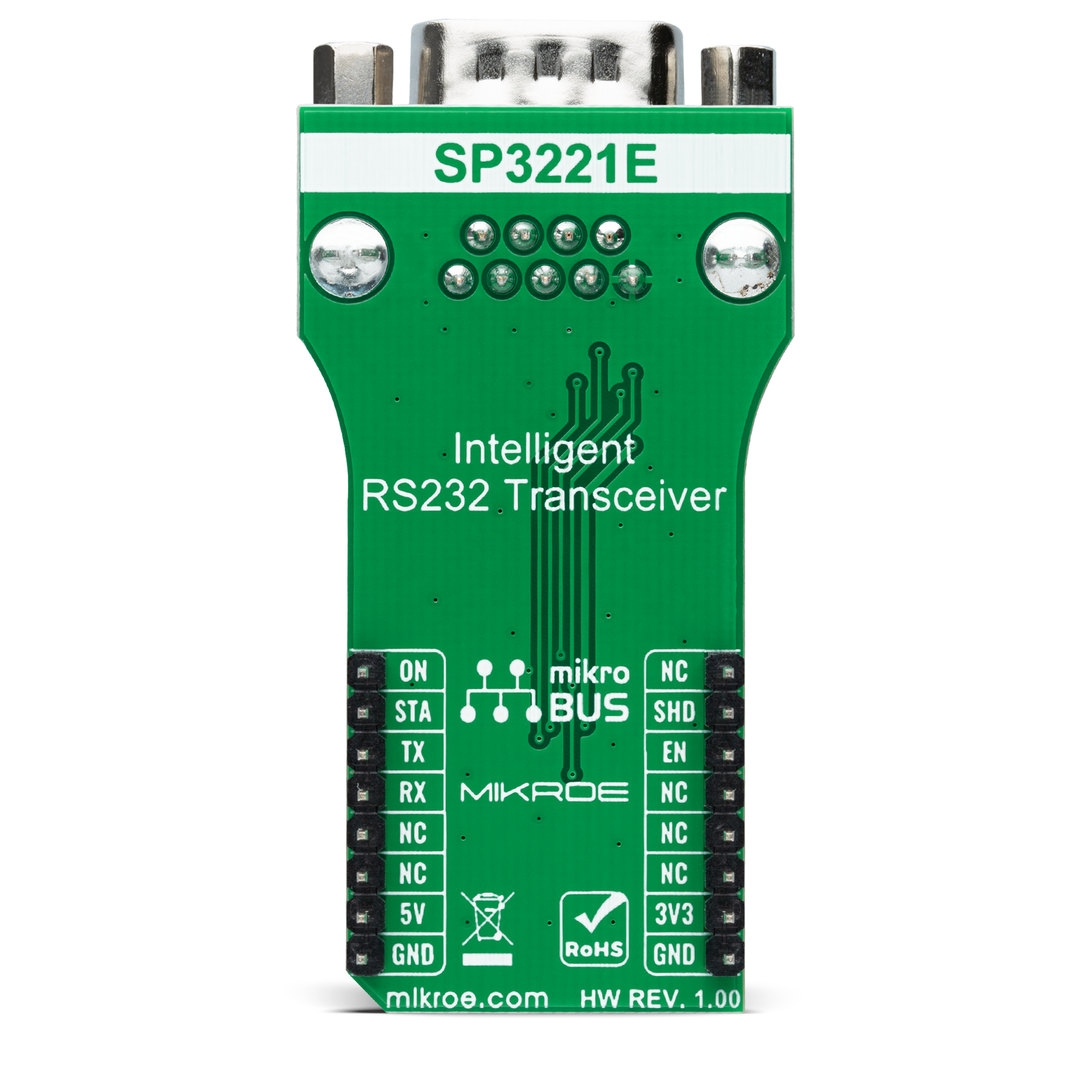
RS232 3 Click is based on the SP3221E, a low-power, RS232 transceiver (single driver/single receiver) solution with a 250kbps data rate from MaxLinear. The SP3221E uses an internal high-efficiency, charge-pump power supply and complies with EIA/TIA-232-F standards when powered by any of the mikroBUS™ power rails. This charge pump and MaxLinear's driver architecture allow the SP3221E to deliver compliant RS-232 performance from a single power supply intended for portable or handheld applications such as embedded computers, data logging devices, medical diagnostics, and remote sensors. The SP3221E communicates with MCU using the UART interface with the default baud rate of 115200bps for data transfer. It also comes equipped with the standard DB-9 connector, which makes interfacing with the RS232 simple and easy,
and a red LED indicator labeled STATUS that indicates whether a valid RS232 signal is present. This signal is also routed to the INT pin of the mikroBUS™ socket, labeled as STA. Alongside UART communication, several signals connected to the mikroBUS™ socket pins are also used to forward the information to the MCU. For proper operation of SP3221E, this board uses a combination of EN and SHD pins, routed to the default place of the CS and RST pins of the mikroBUS™ socket. The receiver is active when the AUTO ON-LINE® circuitry is enabled or in Shutdown. The AUTO ON-LINE® feature, controlled via the ON pin routed to the PWM pin of the mikroBUS™ socket, allows the SP3221E to automatically "Wake-Up" from a Shutdown state when an RS232 cable is connected and a peripheral device is turned on.
During the Shutdown, the receiver will continue to be active. The device goes into Standby mode if there is no activity at the receiver for a more extended period or when the SHD pin is enabled. Also, driving the EN pin to a high state forces the receiver's output into a high impedance state. This Click board™ can operate with either 3.3V or 5V logic voltage levels selected via the VCC SEL jumper. This way, both 3.3V and 5V capable MCUs can use the communication lines properly. However, the Click board™ comes equipped with a library containing easy-to-use functions and an example code that can be used, as a reference, for further development.
Features overview
Development board
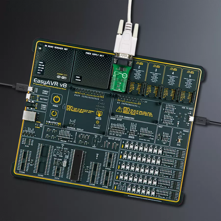
EasyAVR v8 is a development board designed to rapidly develop embedded applications based on 8-bit AVR microcontrollers (MCUs). Redesigned from the ground up, EasyAVR v8 offers a familiar set of standard features, as well as some new and unique features standard for the 8th generation of development boards: programming and debugging over the WiFi network, connectivity provided by USB-C connectors, support for a wide range of different MCUs, and more. The development board is designed so that the developer has everything that might be needed for the application development, following the Swiss Army knife concept: a highly advanced programmer/debugger module, a reliable power supply module, and a USB-UART connectivity option. EasyAVR v8 board offers several different DIP sockets, covering a wide range of 8-bit AVR MCUs, from the smallest
AVR MCU devices with only eight pins, all the way up to 40-pin "giants". The development board supports the well-established mikroBUS™ connectivity standard, offering five mikroBUS™ sockets, allowing access to a huge base of Click boards™. EasyAVR v8 offers two display options, allowing even the basic 8-bit AVR MCU devices to utilize them and display graphical or textual content. One of them is the 1x20 graphical display connector, compatible with the familiar Graphical Liquid Crystal Display (GLCD) based on the KS108 (or compatible) display driver, and EasyTFT board that contains TFT Color Display MI0283QT-9A, which is driven by ILI9341 display controller, capable of showing advanced graphical content. The other option is the 2x16 character LCD module, a four-bit display module with an embedded character-based display controller. It
requires minimal processing power from the host MCU for its operation. There is a wide range of useful interactive options at the disposal: high-quality buttons with selectable press levels, LEDs, pull-up/pulldown DIP switches, and more. All these features are packed on a single development board, which uses innovative manufacturing technologies, delivering a fluid and immersive working experience. The EasyAVR v8 development board is also integral to the MIKROE rapid development ecosystem. Natively supported by the MIKROE Software toolchain, backed up by hundreds of different Click board™ designs with their number growing daily, it covers many different prototyping and development aspects, thus saving precious development time.

Microcontroller Overview
MCU Card / MCU

Architecture
AVR
MCU Memory (KB)
64
Silicon Vendor
Microchip
Pin count
40
RAM (Bytes)
4096
You complete me!
Accessories
DB9 Cable Female-to-Female (2m) cable is essential for establishing dependable serial data connections between devices. With its DB9 female connectors on both ends, this cable enables a seamless link between various equipment, such as computers, routers, switches, and other serial devices. Measuring 2 meters in length, it offers flexibility in arranging your setup without compromising data transmission quality. Crafted with precision, this cable ensures consistent and reliable data exchange, making it suitable for industrial applications, office environments, and home setups. Whether configuring networking equipment, accessing console ports, or utilizing serial peripherals, this cable's durable construction and robust connectors guarantee a stable connection. Simplify your data communication needs with the 2m DB9 female-to-female cable, an efficient solution designed to meet your serial connectivity requirements easily and efficiently.

Used MCU Pins
mikroBUS™ mapper
Take a closer look
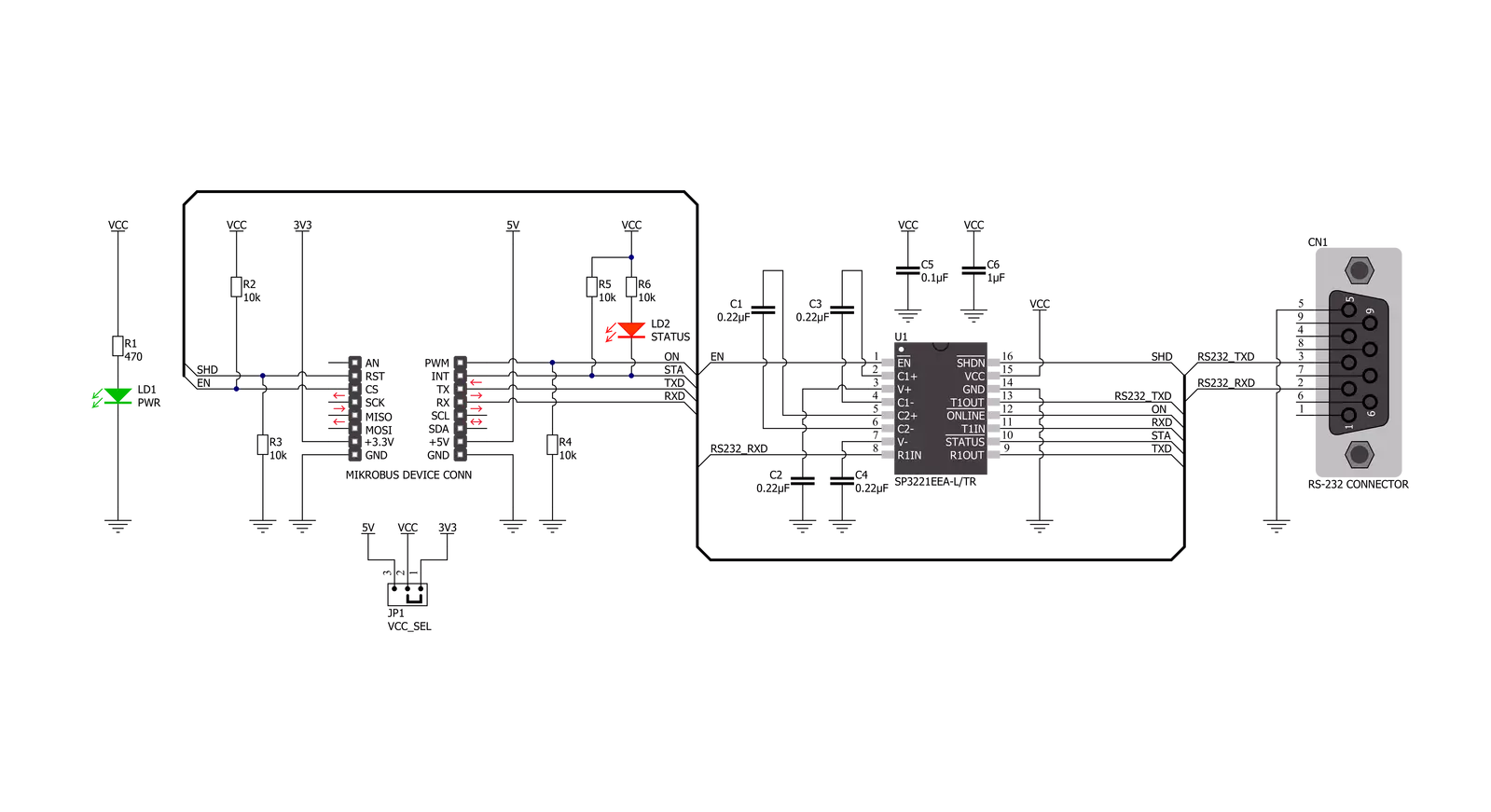
Click board™ Schematic
Step by step
Project assembly

Start by selecting your development board and Click board™. Begin with the EasyAVR v8 as your development board.


Track your results in real time
Application Output
1. Application Output - In Debug mode, the 'Application Output' window enables real-time data monitoring, offering direct insight into execution results. Ensure proper data display by configuring the environment correctly using the provided tutorial.

2. UART Terminal - Use the UART Terminal to monitor data transmission via a USB to UART converter, allowing direct communication between the Click board™ and your development system. Configure the baud rate and other serial settings according to your project's requirements to ensure proper functionality. For step-by-step setup instructions, refer to the provided tutorial.

3. Plot Output - The Plot feature offers a powerful way to visualize real-time sensor data, enabling trend analysis, debugging, and comparison of multiple data points. To set it up correctly, follow the provided tutorial, which includes a step-by-step example of using the Plot feature to display Click board™ readings. To use the Plot feature in your code, use the function: plot(*insert_graph_name*, variable_name);. This is a general format, and it is up to the user to replace 'insert_graph_name' with the actual graph name and 'variable_name' with the parameter to be displayed.

Software Support
Library Description
This library contains API for RS232 3 Click driver.
Key functions:
rs2323_generic_writeThis function writes a desired number of data bytes by using UART serial interface.rs2323_generic_readThis function reads a desired number of data bytes by using UART serial interface.
Open Source
Code example
The complete application code and a ready-to-use project are available through the NECTO Studio Package Manager for direct installation in the NECTO Studio. The application code can also be found on the MIKROE GitHub account.
/*!
 * @file main.c
 * @brief RS232 3 Click Example.
 *
 * # Description
 * This example demonstrates the use of an RS232 3 Click board by showing
 * the communication between the two Click board configured as a receiver and transmitter.
 *
 * The demo application is composed of two sections :
 *
 * ## Application Init
 * Initializes the driver and logger and displays the selected application mode.
 *
 * ## Application Task
 * Depending on the selected mode, it reads all the received data or
 * sends the desired message every 3 seconds.
 *
 * @author Stefan Filipovic
 *
 */

#include "board.h"
#include "log.h"
#include "rs2323.h"

// Comment out the line below in order to switch the application mode to receiver
#define DEMO_APP_TRANSMITTER

#define DEMO_TEXT_MESSAGE           "MikroE - RS232 3 Click board\r\n"

static rs2323_t rs2323;
static log_t logger;

void application_init ( void )
{
    log_cfg_t log_cfg;  /**< Logger config object. */
    rs2323_cfg_t rs2323_cfg;  /**< Click config object. */

    /**
     * Logger initialization.
     * Default baud rate: 115200
     * Default log level: LOG_LEVEL_DEBUG
     * @note If USB_UART_RX and USB_UART_TX
     * are defined as HAL_PIN_NC, you will
     * need to define them manually for log to work.
     * See @b LOG_MAP_USB_UART macro definition for detailed explanation.
     */
    LOG_MAP_USB_UART( log_cfg );
    log_init( &logger, &log_cfg );
    log_info( &logger, " Application Init " );

    // Click initialization.
    rs2323_cfg_setup( &rs2323_cfg );
    RS2323_MAP_MIKROBUS( rs2323_cfg, MIKROBUS_1 );
    if ( UART_ERROR == rs2323_init( &rs2323, &rs2323_cfg ) )
    {
        log_error( &logger, " Communication init." );
        for ( ; ; );
    }
#ifdef DEMO_APP_TRANSMITTER
    log_printf( &logger, " Application Mode: Transmitter\r\n" );
#else
    log_printf( &logger, " Application Mode: Receiver\r\n" );
#endif
    log_info( &logger, " Application Task " );
}

void application_task ( void )
{
#ifdef DEMO_APP_TRANSMITTER
    rs2323_generic_write( &rs2323, DEMO_TEXT_MESSAGE, strlen( DEMO_TEXT_MESSAGE ) );
    log_printf( &logger, "%s", ( char * ) DEMO_TEXT_MESSAGE );
    Delay_ms ( 1000 );
    Delay_ms ( 1000 );
    Delay_ms ( 1000 );
#else
    uint8_t rx_data;
    if ( rs2323_generic_read( &rs2323, &rx_data, 1 ) > 0 )
    {
        log_printf( &logger, "%c", rx_data );
    }
#endif
}

int main ( void )
{
    /* Do not remove this line or clock might not be set correctly. */
    #ifdef PREINIT_SUPPORTED
    preinit();
    #endif

    application_init( );

    for ( ; ; )
    {
        application_task( );
    }

    return 0;
}

// ------------------------------------------------------------------------ END