Upgrade your projects with DRV8317H and STM32F031K6
Improve your applications with our smart, reliable brushless motor driver!

Published Oct 01, 2024
Click board™
Brushless 26 Click
Dev. board
Nucleo 32 with STM32F031K6 MCU
Compiler
NECTO Studio
MCU
STM32F031K6
Whether you're building drones or robotics, our brushless motor drivers offer the perfect blend of power and agility, ensuring your devices perform at their peak.
A
A
Hardware Overview
How does it work?
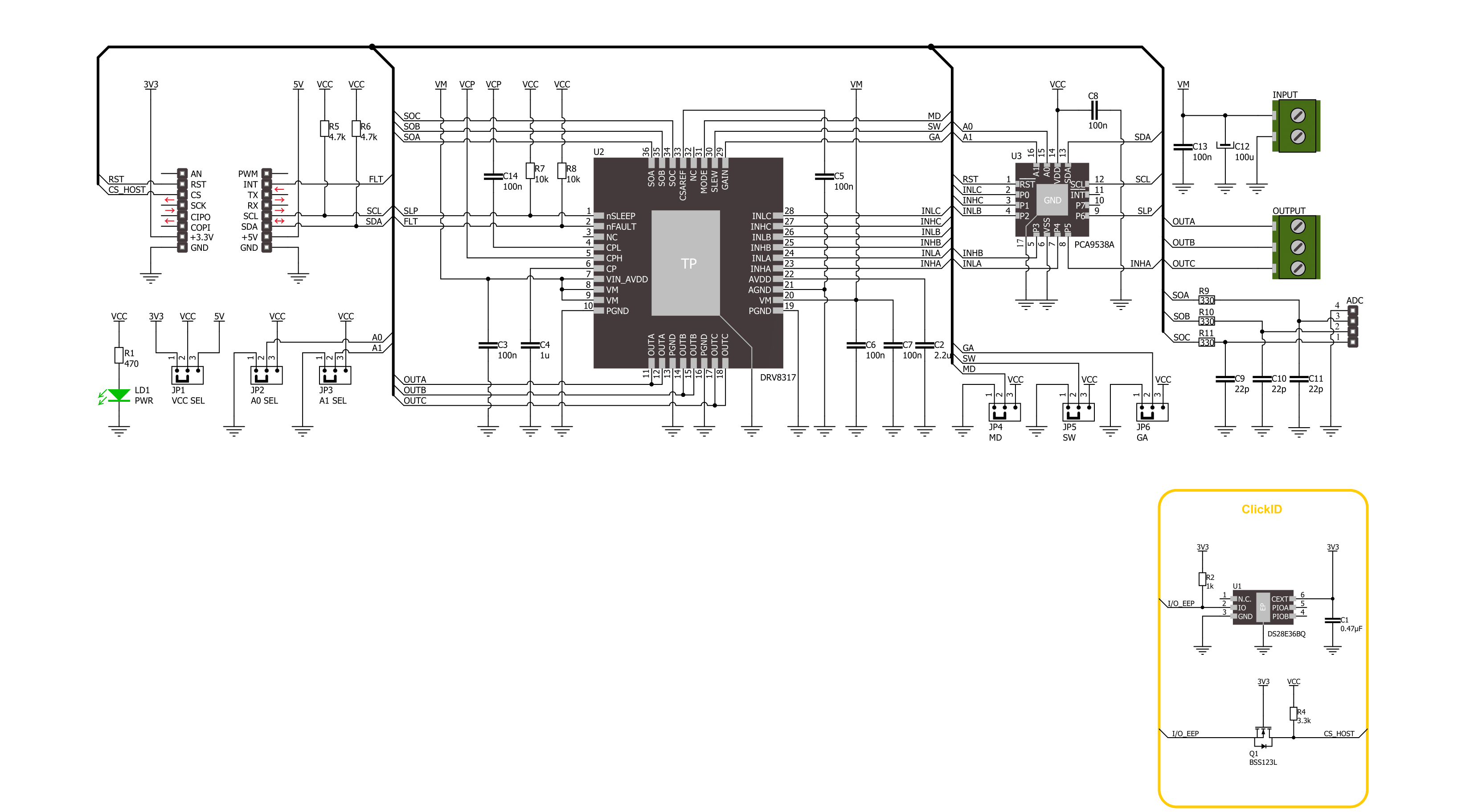
Brushless 26 Click is based on the DRV8317H, a three-phase PWM motor driver from Texas Instruments. Its integrated protection features include VM undervoltage lockout, VM overvoltage protection, charge pump undervoltage, overcurrent protection, overtemperature warning and shutdown, and fault condition indication pin. The motor driver provides two configurable schemes, a 6x or a 3x PWM, which can be used to implement sensor or sensor-less field-oriented control (FOC), sinusoidal control, or trapezoidal control using an external microcontroller. It is capable of driving a PWM frequency of up to 200KHz. To control all high and low side driver control inputs of the DRV8317H, Brushless 26 Click features the PCA9538A, a low-voltage 8-bit I2C I/O port with interrupt and reset from NXP. Besides driver control
inputs, this I/O port also controls the Sleep mode of the motor driver. The BLDC motor can be connected over the screw terminal, labeled U, V, and W. Additional screw terminal is just aside for connecting an external power supply in a range of 4.5V up to 20V. The DRV8317H is a hardware variant of this motor driver, so the Brushless 26 Click is equipped with jumper selections of the gain, slew, and mode; by default, all three are set to 0. This way, you can set the current sense amplifier gain (GA) and output slew rate (SW) through pin voltage levels. The mode jumper (MD) allows you to use a 6x or 3x PWM mode. The 6x PWM is set by default. Additionally, three current sense amplifiers are available over the 4-pin header labeled A1, A2, and A3. Brushless 26 Click uses a standard 2-wire I2C interface of the PCA9538A to
communicate with the host MCU, supporting clock frequencies up to 400kHz. The I2C address of the PCA9538A can be set over the ADDR SEL jumpers, where 0 is selected by default. If a fault condition occurs, the DRV8317H will pull the FLT pin to a low logic state. The RST pin resets the PCA9538A I/O port. This Click board™ can operate with either 3.3V or 5V logic voltage levels selected via the VCC SEL jumper. This way, both 3.3V and 5V capable MCUs can use the communication lines properly. Also, this Click board™ comes equipped with a library containing easy-to-use functions and an example code that can be used as a reference for further development.

Features overview
Development board
Nucleo 32 with STM32F031K6 MCU board provides an affordable and flexible platform for experimenting with STM32 microcontrollers in 32-pin packages. Featuring Arduino™ Nano connectivity, it allows easy expansion with specialized shields, while being mbed-enabled for seamless integration with online resources. The
board includes an on-board ST-LINK/V2-1 debugger/programmer, supporting USB reenumeration with three interfaces: Virtual Com port, mass storage, and debug port. It offers a flexible power supply through either USB VBUS or an external source. Additionally, it includes three LEDs (LD1 for USB communication, LD2 for power,
and LD3 as a user LED) and a reset push button. The STM32 Nucleo-32 board is supported by various Integrated Development Environments (IDEs) such as IAR™, Keil®, and GCC-based IDEs like AC6 SW4STM32, making it a versatile tool for developers.

Microcontroller Overview
MCU Card / MCU

Architecture
ARM Cortex-M0
MCU Memory (KB)
32
Silicon Vendor
STMicroelectronics
Pin count
32
RAM (Bytes)
4096
You complete me!
Accessories
Click Shield for Nucleo-32 is the perfect way to expand your development board's functionalities with STM32 Nucleo-32 pinout. The Click Shield for Nucleo-32 provides two mikroBUS™ sockets to add any functionality from our ever-growing range of Click boards™. We are fully stocked with everything, from sensors and WiFi transceivers to motor control and audio amplifiers. The Click Shield for Nucleo-32 is compatible with the STM32 Nucleo-32 board, providing an affordable and flexible way for users to try out new ideas and quickly create prototypes with any STM32 microcontrollers, choosing from the various combinations of performance, power consumption, and features. The STM32 Nucleo-32 boards do not require any separate probe as they integrate the ST-LINK/V2-1 debugger/programmer and come with the STM32 comprehensive software HAL library and various packaged software examples. This development platform provides users with an effortless and common way to combine the STM32 Nucleo-32 footprint compatible board with their favorite Click boards™ in their upcoming projects.

Brushless DC (BLDC) Motor with a Hall sensor represents a high-performance motor from the 42BLF motor series. This motor, wired in a star configuration, boasts a Hall Effect angle of 120°, ensuring precise and reliable performance. With a compact motor length of 47mm and a lightweight design tipping the scales at just 0.29kg, this BLDC motor is engineered to meet your needs. Operating flawlessly at a voltage rating of 24VDC and a speed range of 4000 ± 10% RPM, this motor offers consistent and dependable power. It excels in a normal operational temperature range from -20 to +50°C, maintaining efficiency with a rated current of 1.9A. Also, this product seamlessly integrates with all Brushless Click boards™ and those that require BLDC motors with Hall sensors.

Used MCU Pins
mikroBUS™ mapper
Take a closer look
Click board™ Schematic
Step by step
Project assembly

Start by selecting your development board and Click board™. Begin with the Nucleo 32 with STM32F031K6 MCU as your development board.


Software Support
Library Description
This library contains API for Brushless 26 Click driver.
Key functions:
brushless26_reset_port_exp- Brushless 26 reset port expander function.brushless26_set_pins- Brushless 26 set pins function.brushless26_drive_motor- Brushless 26 drive motor function.
Open Source
Code example
The complete application code and a ready-to-use project are available through the NECTO Studio Package Manager for direct installation in the NECTO Studio. The application code can also be found on the MIKROE GitHub account.
/*!
 * @file main.c
 * @brief Brushless 26 Click example
 *
 * # Description
 * This example demonstrates the use of the Brushless 26 Click board by driving the
 * motor in both directions at different speeds.
 *
 * The demo application is composed of two sections :
 *
 * ## Application Init
 * Initializes the driver and performs the Click default configuration.
 *
 * ## Application Task
 * Drives the motor in both directions and changes the motor speed approximately every 2 seconds.
 * The driving direction and speed will be displayed on the USB UART.
 *
 * @author Stefan Ilic
 *
 */

#include "board.h"
#include "log.h"
#include "brushless26.h"

static brushless26_t brushless26;
static log_t logger;

void application_init ( void )
{
    log_cfg_t log_cfg;  /**< Logger config object. */
    brushless26_cfg_t brushless26_cfg;  /**< Click config object. */

    /**
     * Logger initialization.
     * Default baud rate: 115200
     * Default log level: LOG_LEVEL_DEBUG
     * @note If USB_UART_RX and USB_UART_TX
     * are defined as HAL_PIN_NC, you will
     * need to define them manually for log to work.
     * See @b LOG_MAP_USB_UART macro definition for detailed explanation.
     */
    LOG_MAP_USB_UART( log_cfg );
    log_init( &logger, &log_cfg );
    log_info( &logger, " Application Init " );

    // Click initialization.
    brushless26_cfg_setup( &brushless26_cfg );
    BRUSHLESS26_MAP_MIKROBUS( brushless26_cfg, MIKROBUS_1 );
    if ( I2C_MASTER_ERROR == brushless26_init( &brushless26, &brushless26_cfg ) )
    {
        log_error( &logger, " Communication init." );
        for ( ; ; );
    }

    if ( BRUSHLESS26_ERROR == brushless26_default_cfg ( &brushless26 ) )
    {
        log_error( &logger, " Default configuration." );
        for ( ; ; );
    }

    log_info( &logger, " Application Task");
}

void application_task ( void )
{
    log_printf ( &logger, "\r\n Driving motor clockwise \r\n" );
    for ( uint8_t speed = BRUSHLESS26_SPEED_MIN; speed <= BRUSHLESS26_SPEED_MAX; speed += 20 )
    {
        log_printf ( &logger, " Speed gain: %u\r\n", ( uint16_t ) speed );
        if ( BRUSHLESS26_OK != brushless26_drive_motor ( &brushless26, BRUSHLESS26_DIR_CW, speed, 2000 ) )
        {
            log_error ( &logger, " Drive motor " );
        }
    }
    Delay_ms ( 1000 );

    log_printf ( &logger, "\r\n Driving motor counter-clockwise \r\n" );
    for ( uint8_t speed = BRUSHLESS26_SPEED_MIN; speed <= BRUSHLESS26_SPEED_MAX; speed += 20 )
    {
        log_printf ( &logger, " Speed gain: %u\r\n", ( uint16_t ) speed );
        if ( BRUSHLESS26_OK != brushless26_drive_motor ( &brushless26, BRUSHLESS26_DIR_CCW, speed, 2000 ) )
        {
            log_error ( &logger, " Drive motor " );
        }
    }
    Delay_ms ( 1000 );
}

int main ( void )
{
    /* Do not remove this line or clock might not be set correctly. */
    #ifdef PREINIT_SUPPORTED
    preinit();
    #endif

    application_init( );

    for ( ; ; )
    {
        application_task( );
    }

    return 0;
}

// ------------------------------------------------------------------------ END
Additional Support
Resources
Category:Brushless


