Detect DTMF tones accurately and effortlessly with MT8870D and STM32F031K6
Revolutionizing tone decoding: Unveiling the ultimate DTMF receiver
Published Oct 01, 2024
Click board™
DTMF Decoder Click
Dev. board
Nucleo 32 with STM32F031K6 MCU
Compiler
NECTO Studio
MCU
STM32F031K6
Explore the cutting-edge DTMF receiver that seamlessly combines band-split filtering and digital decoding, enabling the detection and decoding of all 16 DTMF tone-pairs into a 4-bit code
A
A
Hardware Overview
How does it work?
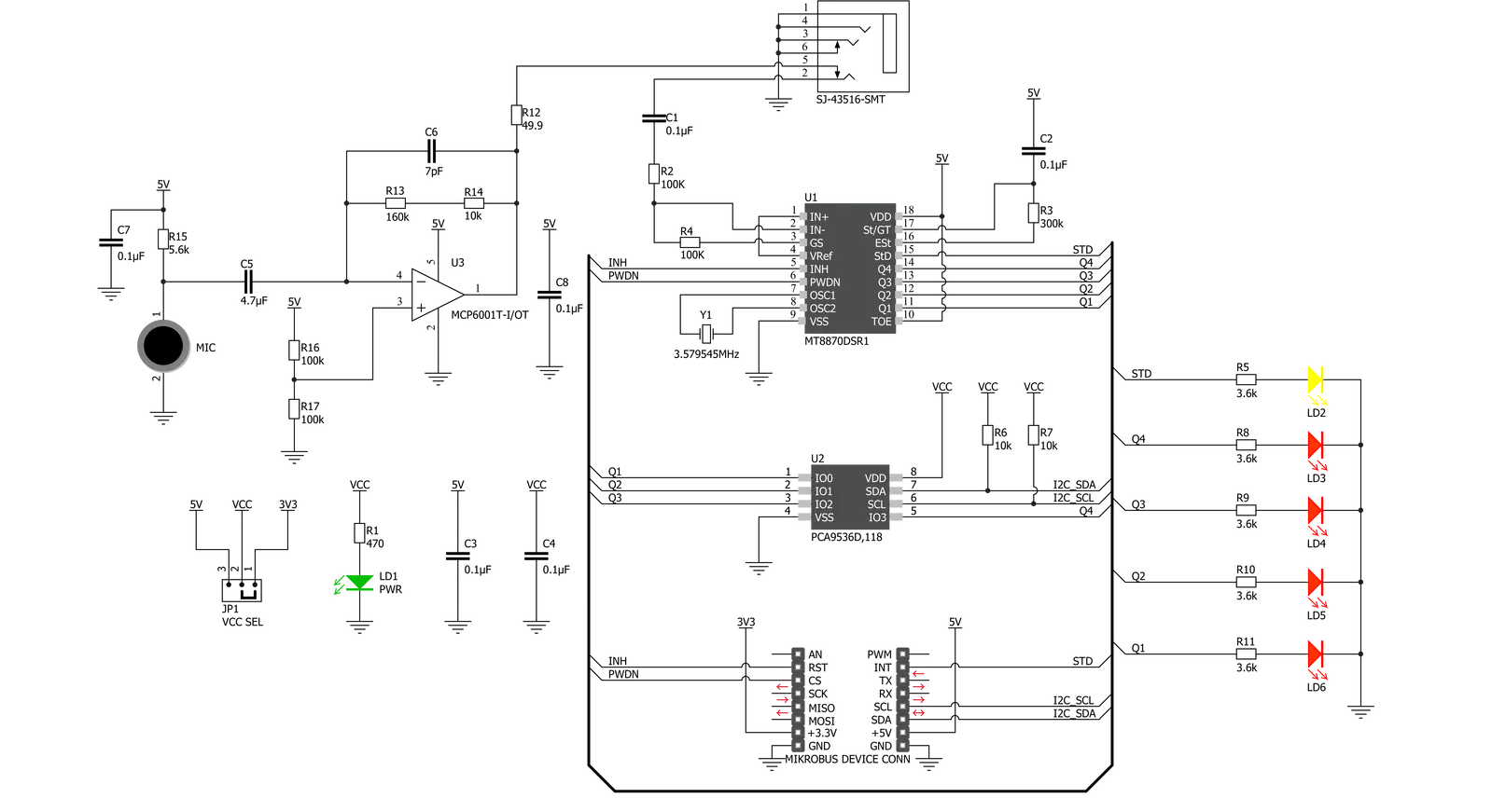
DTMF Decoder Click is based on the MT8870D, an integrated DTMF receiver with enhanced sensitivity from Microchip Technology. It offers low power consumption and high performance. It consists of a band split filter section separating the high and low group tones, followed by a digital counting section that verifies the received tones' frequency and duration before passing the corresponding code to the output bus. This Click board™ has two ways to detect tones: a mobile phone with a 3.5mm jack, which provides the DTMF signals to the MT8870D decoder, or an onboard microphone to listen to the DTMF tones generated by the cell phone. The MT8870D uses digital counting techniques to detect and decode all 16 DTMF tone-pairs into a 4-bit code. DTMF
Decoder Click communicates with MCU using a standard I2C 2-Wire interface, with a clock frequency up to 100kHz in the Standard and 400kHz in the Fast Mode. Using the PCA9536 port expander that communicates with the MCU via I2C communication, it is possible to display visually, in binary form, the digit of the pressed number. The digit in binary form is then visually displayed using four red LEDs, labeled from Q1 to Q4, in the board's upper right corner. This Click board™ also has a power-down feature routed on the CS pin of the mikroBUS™ socket labeled as PWD. A logic high applied to pin PWD will power down the device to minimize the power consumption in a Standby mode, which stops the oscillator and the filters' functions. Also, it uses the
interrupt pin of the mikroBUS™ labeled as STD with an additional LED indicator signaling that a received tone pair has been registered, and the INH pin, which inhibits the detection of tones representing characters A, B, C, and D. The output code will remain the same as the previously detected code. This Click board™ can operate with either 3.3V or 5V logic voltage levels selected via the VCC SEL jumper. This way, both 3.3V and 5V capable MCUs can use the communication lines properly. Also, this Click board™ comes equipped with a library containing easy-to-use functions and an example code that can be used as a reference for further development.

Features overview
Development board
Nucleo 32 with STM32F031K6 MCU board provides an affordable and flexible platform for experimenting with STM32 microcontrollers in 32-pin packages. Featuring Arduino™ Nano connectivity, it allows easy expansion with specialized shields, while being mbed-enabled for seamless integration with online resources. The
board includes an on-board ST-LINK/V2-1 debugger/programmer, supporting USB reenumeration with three interfaces: Virtual Com port, mass storage, and debug port. It offers a flexible power supply through either USB VBUS or an external source. Additionally, it includes three LEDs (LD1 for USB communication, LD2 for power,
and LD3 as a user LED) and a reset push button. The STM32 Nucleo-32 board is supported by various Integrated Development Environments (IDEs) such as IAR™, Keil®, and GCC-based IDEs like AC6 SW4STM32, making it a versatile tool for developers.

Microcontroller Overview
MCU Card / MCU

Architecture
ARM Cortex-M0
MCU Memory (KB)
32
Silicon Vendor
STMicroelectronics
Pin count
32
RAM (Bytes)
4096
You complete me!
Accessories
Click Shield for Nucleo-32 is the perfect way to expand your development board's functionalities with STM32 Nucleo-32 pinout. The Click Shield for Nucleo-32 provides two mikroBUS™ sockets to add any functionality from our ever-growing range of Click boards™. We are fully stocked with everything, from sensors and WiFi transceivers to motor control and audio amplifiers. The Click Shield for Nucleo-32 is compatible with the STM32 Nucleo-32 board, providing an affordable and flexible way for users to try out new ideas and quickly create prototypes with any STM32 microcontrollers, choosing from the various combinations of performance, power consumption, and features. The STM32 Nucleo-32 boards do not require any separate probe as they integrate the ST-LINK/V2-1 debugger/programmer and come with the STM32 comprehensive software HAL library and various packaged software examples. This development platform provides users with an effortless and common way to combine the STM32 Nucleo-32 footprint compatible board with their favorite Click boards™ in their upcoming projects.

Used MCU Pins
mikroBUS™ mapper
Take a closer look
Click board™ Schematic
Step by step
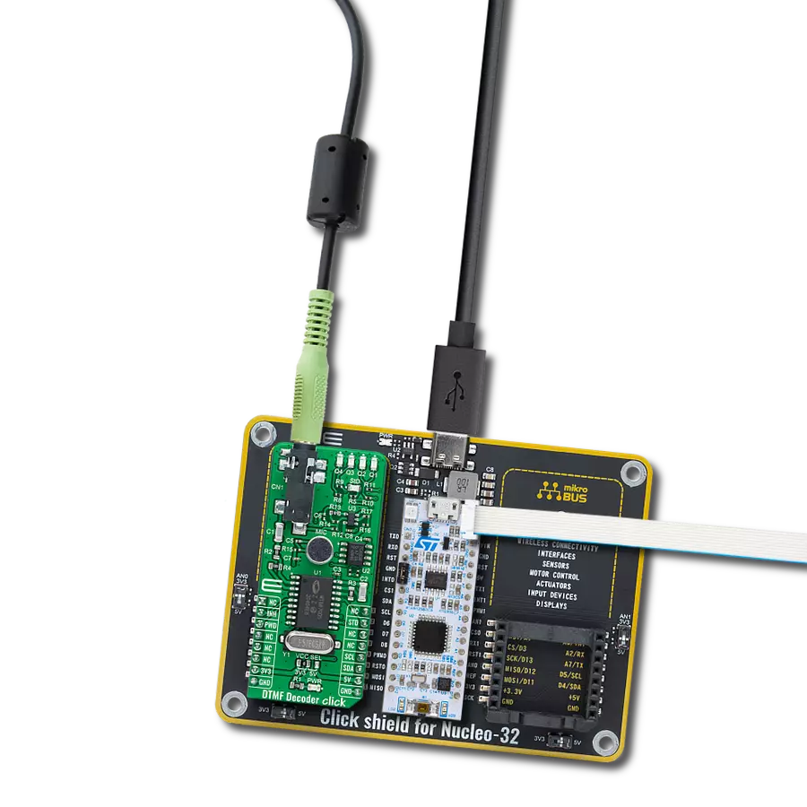
Project assembly

Start by selecting your development board and Click board™. Begin with the Nucleo 32 with STM32F031K6 MCU as your development board.


Track your results in real time
Application Output
1. Application Output - In Debug mode, the 'Application Output' window enables real-time data monitoring, offering direct insight into execution results. Ensure proper data display by configuring the environment correctly using the provided tutorial.

2. UART Terminal - Use the UART Terminal to monitor data transmission via a USB to UART converter, allowing direct communication between the Click board™ and your development system. Configure the baud rate and other serial settings according to your project's requirements to ensure proper functionality. For step-by-step setup instructions, refer to the provided tutorial.

3. Plot Output - The Plot feature offers a powerful way to visualize real-time sensor data, enabling trend analysis, debugging, and comparison of multiple data points. To set it up correctly, follow the provided tutorial, which includes a step-by-step example of using the Plot feature to display Click board™ readings. To use the Plot feature in your code, use the function: plot(*insert_graph_name*, variable_name);. This is a general format, and it is up to the user to replace 'insert_graph_name' with the actual graph name and 'variable_name' with the parameter to be displayed.

Software Support
Library Description
This library contains API for DTMF Decoder Click driver.
Key functions:
dtmfdecoder_tone_read- This function reads a last registered tone and returns decoded data in character formatdtmfdecoder_delayed_steering_check- This function checks the state of the StD pindtmfdecoder_powerdown_off- This function powers up the device and along with the oscillator
Open Source
Code example
The complete application code and a ready-to-use project are available through the NECTO Studio Package Manager for direct installation in the NECTO Studio. The application code can also be found on the MIKROE GitHub account.
/*!
 * @file main.c
 * @brief DTMFDecoder Click example
 *
 * # Description
 * This example shows the basic tone capture of
 * DTMF frequencies, decoding and representing
 * them on the UART LOG.
 *
 * The demo application is composed of two sections :
 *
 * ## Application Init
 * Initializes I2C and UART LOG drivers and powers
 * on the device.
 *
 * ## Application Task
 * Checks the delayed steering for incoming tones
 * and decoding them on the UART LOG. Holding the
 * same key will recognize multiple tone generation,
 * the tone register delay constant can be set to
 * adjust the tolerance.
 *
 * @author Stefan Nikolic
 *
 */

#include "board.h"
#include "log.h"
#include "dtmfdecoder.h"

static dtmfdecoder_t dtmfdecoder;
static log_t logger;

static const uint16_t tone_register_delay = 200;

void application_init ( void ) {
    log_cfg_t log_cfg;                  /**< Logger config object. */
    dtmfdecoder_cfg_t dtmfdecoder_cfg;  /**< Click config object. */

    /**
     * Logger initialization.
     * Default baud rate: 115200
     * Default log level: LOG_LEVEL_DEBUG
     * @note If USB_UART_RX and USB_UART_TX
     * are defined as HAL_PIN_NC, you will
     * need to define them manually for log to work.
     * See @b LOG_MAP_USB_UART macro definition for detailed explanation.
     */
    LOG_MAP_USB_UART( log_cfg );
    log_init( &logger, &log_cfg );
    log_info( &logger, " Application Init " );

    // Click initialization.

    dtmfdecoder_cfg_setup( &dtmfdecoder_cfg );
    DTMFDECODER_MAP_MIKROBUS( dtmfdecoder_cfg, MIKROBUS_1 );
    err_t init_flag = dtmfdecoder_init( &dtmfdecoder, &dtmfdecoder_cfg );
    if ( init_flag == I2C_MASTER_ERROR ) {
        log_error( &logger, " Application Init Error. " );
        log_info( &logger, " Please, run program again... " );

        for ( ; ; );
    }

    dtmfdecoder_default_cfg ( &dtmfdecoder );
    Delay_ms ( 100 );
    log_info( &logger, " Application Task " );
}

void application_task ( void ) {
    uint8_t result;

    if ( dtmfdecoder_delayed_steering_check( &dtmfdecoder ) ) {
        result = dtmfdecoder_tone_read( &dtmfdecoder );
        log_printf( &logger, " Detected key tone:\t%c\r\n", result );
        Delay_ms ( tone_register_delay );
    }
}

int main ( void )
{
    /* Do not remove this line or clock might not be set correctly. */
    #ifdef PREINIT_SUPPORTED
    preinit();
    #endif

    application_init( );

    for ( ; ; )
    {
        application_task( );
    }

    return 0;
}

// ------------------------------------------------------------------------ END


