Craft seamless signals for mobile communication systems with HT9200A and STM32F031K6
Behind the dial: Uncover the brilliance of the DTMF decoder

Published Oct 01, 2024
Click board™
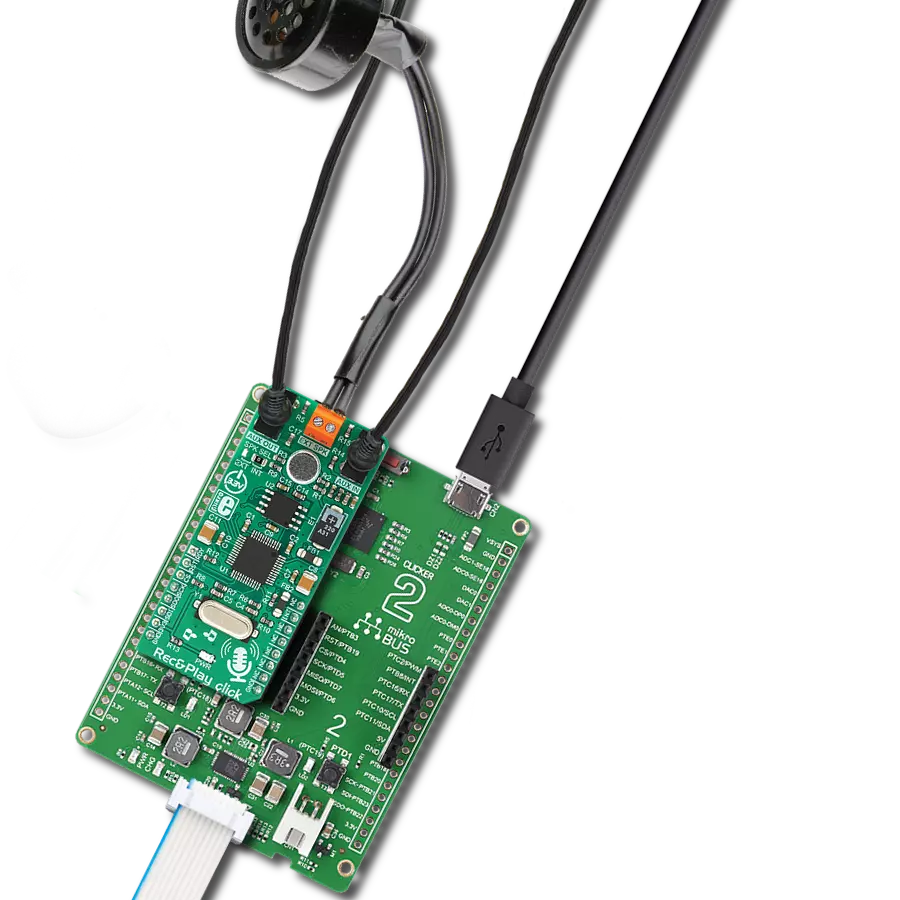
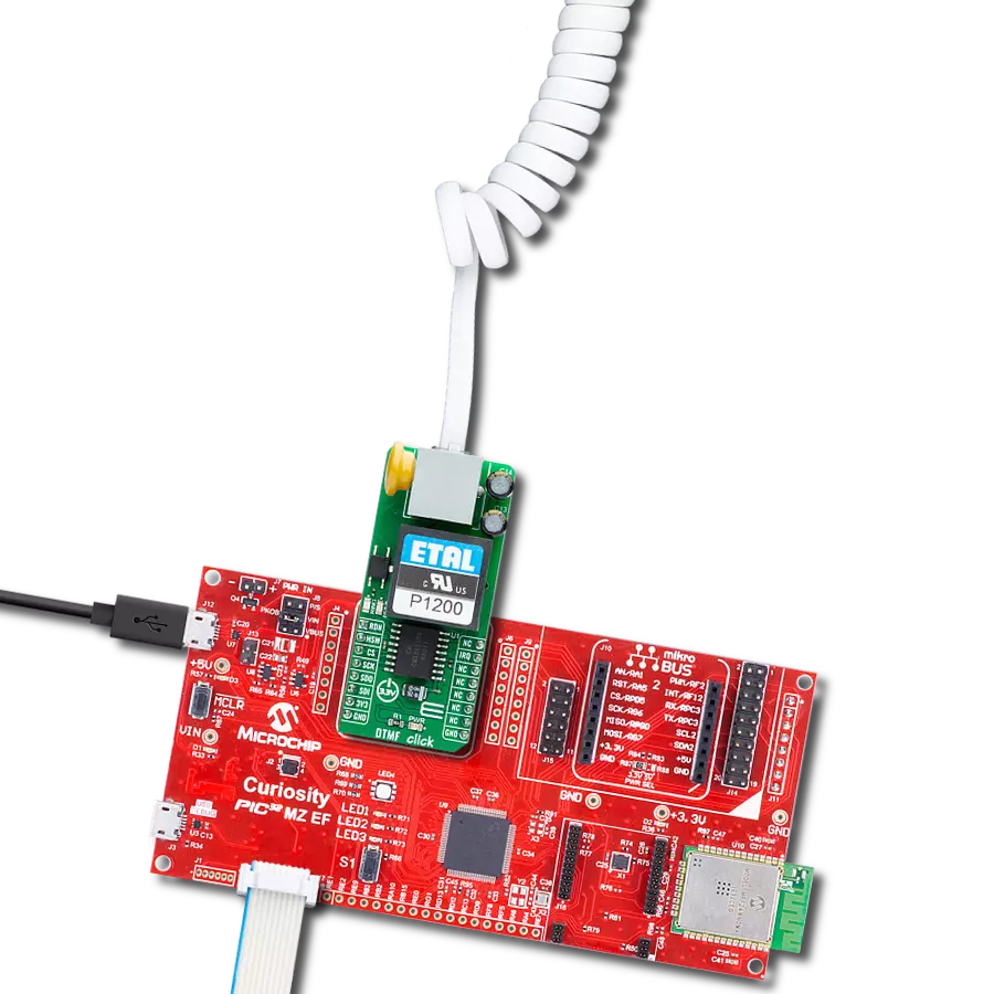
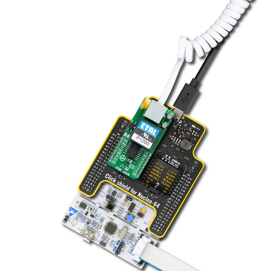
DTMF Generator Click
Dev. board
Nucleo 32 with STM32F031K6 MCU
Compiler
NECTO Studio
MCU
STM32F031K6
Journey into the world of DTMF signal generation, where we uncover the magic that results in the creation of Dual-Tone Multi-Frequency signals vital for mobile communication systems
A
A
Hardware Overview
How does it work?
DTMF Generator Click is based on the HT9200A, a dual-tone multi-frequency decoder from Holtek Semiconductor for mobile communication systems. The HT9200A is an SMD tone generator IC designed for MCU interfaces. It can be instructed by an MCU to generate 16 dual tones and eight single tones from the DTMF pin, and it provides a Serial Mode. The system oscillator of HT9200A consists of an inverter, a bias resistor, and the required load capacitor on a chip. The oscillator function is implemented with a standard 3.579545MHz crystal connected to the X1 and X2 pins of the HT9200A. The operation of the HT9200A is based on GPIO signals fed from the mikroBUS™ to the decoder, DAT, and CLK. There is a connection between the digital codes and the tone output frequency based on the selected desired output frequency. The HT9200A employs a
data input, a 5-bit code, and a synchronous clock to transmit a DTMF signal. Every digit of a transferred number is selected by a series of combinations that consist of 5-bit data. The HT9200A will latch data on the falling edge of the CLK pin and display the output data on its output DTMF pin. Then, via a volume adjustment potentiometer, such a signal is sent to an audio amplifier, the LM386 from Texas Instruments, which represents a mono low-voltage amplifier that can be used in various applications. After the audio amplifier, the desired sound can be detected on the on-board speaker. DTMF Generator Click communicates with MCU using three GPIO pins routed on the CS, RST, and PWM pins of the mikroBUS™ socket labeled CE, DAT, and CLK. CE pin represents the Chip Enable function used to wake up the HT9200A, while DAT
and CLK pins represent data input and synchronous clock input. It also possesses an adjustable potentiometer labeled as VOLUME that adjusts the volume of that signal. It also has a 3.5mm jack output connector that allows the user to use the output DTMF signal in their projects in their way while the signal volume can still be adjusted on the VOLUME potentiometer located on the DTMF Generator Click. This Click board™ can operate with either 3.3V or 5V logic voltage levels selected via the VCC SEL jumper. This way, both 3.3V and 5V capable MCUs can use the communication lines properly. Also, this Click board™ comes equipped with a library containing easy-to-use functions and an example code that can be used as a reference for further development.


Features overview
Development board
Nucleo 32 with STM32F031K6 MCU board provides an affordable and flexible platform for experimenting with STM32 microcontrollers in 32-pin packages. Featuring Arduino™ Nano connectivity, it allows easy expansion with specialized shields, while being mbed-enabled for seamless integration with online resources. The
board includes an on-board ST-LINK/V2-1 debugger/programmer, supporting USB reenumeration with three interfaces: Virtual Com port, mass storage, and debug port. It offers a flexible power supply through either USB VBUS or an external source. Additionally, it includes three LEDs (LD1 for USB communication, LD2 for power,
and LD3 as a user LED) and a reset push button. The STM32 Nucleo-32 board is supported by various Integrated Development Environments (IDEs) such as IAR™, Keil®, and GCC-based IDEs like AC6 SW4STM32, making it a versatile tool for developers.

Microcontroller Overview
MCU Card / MCU

Architecture
ARM Cortex-M0
MCU Memory (KB)
32
Silicon Vendor
STMicroelectronics
Pin count
32
RAM (Bytes)
4096
You complete me!
Accessories
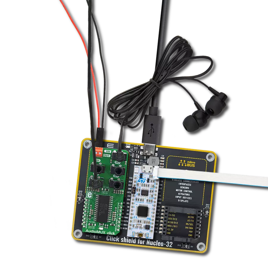
Click Shield for Nucleo-32 is the perfect way to expand your development board's functionalities with STM32 Nucleo-32 pinout. The Click Shield for Nucleo-32 provides two mikroBUS™ sockets to add any functionality from our ever-growing range of Click boards™. We are fully stocked with everything, from sensors and WiFi transceivers to motor control and audio amplifiers. The Click Shield for Nucleo-32 is compatible with the STM32 Nucleo-32 board, providing an affordable and flexible way for users to try out new ideas and quickly create prototypes with any STM32 microcontrollers, choosing from the various combinations of performance, power consumption, and features. The STM32 Nucleo-32 boards do not require any separate probe as they integrate the ST-LINK/V2-1 debugger/programmer and come with the STM32 comprehensive software HAL library and various packaged software examples. This development platform provides users with an effortless and common way to combine the STM32 Nucleo-32 footprint compatible board with their favorite Click boards™ in their upcoming projects.

Used MCU Pins
mikroBUS™ mapper
Take a closer look
Click board™ Schematic

Step by step
Project assembly

Start by selecting your development board and Click board™. Begin with the Nucleo 32 with STM32F031K6 MCU as your development board.


Software Support
Library Description
This library contains API for DTMF Generator Click driver.
Key functions:
dtmfgenerator_set_dat- Set DATA ( RST ) pin state functiondtmfgenerator_power_on- Power ON functiondtmfgenerator_transmit_out_tone- The function transmit duration time of the desired tone
Open Source
Code example
The complete application code and a ready-to-use project are available through the NECTO Studio Package Manager for direct installation in the NECTO Studio. The application code can also be found on the MIKROE GitHub account.
/*!
 * @file main.c
 * @brief DTMF Generator Click Example.
 *
 * # Description
 * This is an example which demonstrates the use of DTMF Generator Click board.
 *
 * The demo application is composed of two sections :
 *
 * ## Application Init
 * Initialization driver enables - GPIO,
 * run the power-on sequence, also write log.
 *
 * ## Application Task
 * DTMF Generator Click board DTMF generator transmits the signal
 * for generating tone for digits :
 * "0", "1", "2", "3", "4", "5", "6", "7", "8", "9",
 * "A", "B", "C", "D", "*" and "#".
 * All data logs write on USB uart changes.
 *
 * @author Stefan Ilic
 *
 */

#include "board.h"
#include "log.h"
#include "dtmfgenerator.h"

static dtmfgenerator_t dtmfgenerator;   /**< DTMF Generator Click driver object. */
static log_t logger;    /**< Logger object. */

static uint16_t signal_duration = 500;

void application_init ( void ) {
    log_cfg_t log_cfg;  /**< Logger config object. */
    dtmfgenerator_cfg_t dtmfgenerator_cfg;  /**< Click config object. */

    /**
     * Logger initialization.
     * Default baud rate: 115200
     * Default log level: LOG_LEVEL_DEBUG
     * @note If USB_UART_RX and USB_UART_TX
     * are defined as HAL_PIN_NC, you will
     * need to define them manually for log to work.
     * See @b LOG_MAP_USB_UART macro definition for detailed explanation.
     */
    LOG_MAP_USB_UART( log_cfg );
    log_init( &logger, &log_cfg );
    log_info( &logger, " Application Init " );

    // Click initialization.
    dtmfgenerator_cfg_setup( &dtmfgenerator_cfg );
    DTMFGENERATOR_MAP_MIKROBUS( dtmfgenerator_cfg, MIKROBUS_1 );
    if ( DIGITAL_OUT_UNSUPPORTED_PIN == dtmfgenerator_init( &dtmfgenerator, &dtmfgenerator_cfg ) ) {
        log_error( &logger, " Application Init Error. " );
        log_info( &logger, " Please, run program again... " );

        for ( ; ; );
    }
    log_printf( &logger, " Powering on device \r\n" );
    log_printf( &logger, "--------------------\r\n" );
    dtmfgenerator_power_on( &dtmfgenerator );
    Delay_ms ( 1000 );
    log_info( &logger, " Application Task " );
}

void application_task ( void ) {
    log_printf( &logger, " TONE      '0' \r\n");
    log_printf( &logger, "---------------\r\n" );
    dtmfgenerator_transmit_out_tone( &dtmfgenerator, DTMFGENERATOR_OUT_TONE_0, signal_duration );
    dtmfgenerator_transmit_out_tone( &dtmfgenerator, DTMFGENERATOR_OUT_TONE_STOP, signal_duration );

    log_printf( &logger, " TONE      '1' \r\n");
    log_printf( &logger, "---------------\r\n" );
    dtmfgenerator_transmit_out_tone( &dtmfgenerator, DTMFGENERATOR_OUT_TONE_1, signal_duration );
    dtmfgenerator_transmit_out_tone( &dtmfgenerator, DTMFGENERATOR_OUT_TONE_STOP, signal_duration );

    log_printf( &logger, " TONE      '2' \r\n");
    log_printf( &logger, "---------------\r\n" );
    dtmfgenerator_transmit_out_tone( &dtmfgenerator, DTMFGENERATOR_OUT_TONE_2, signal_duration );
    dtmfgenerator_transmit_out_tone( &dtmfgenerator, DTMFGENERATOR_OUT_TONE_STOP, signal_duration );

    log_printf( &logger, " TONE      '3' \r\n");
    log_printf( &logger, "---------------\r\n" );
    dtmfgenerator_transmit_out_tone( &dtmfgenerator, DTMFGENERATOR_OUT_TONE_3, signal_duration );
    dtmfgenerator_transmit_out_tone( &dtmfgenerator, DTMFGENERATOR_OUT_TONE_STOP, signal_duration );

    log_printf( &logger, " TONE      '4' \r\n");
    log_printf( &logger, "---------------\r\n" );
    dtmfgenerator_transmit_out_tone( &dtmfgenerator, DTMFGENERATOR_OUT_TONE_4, signal_duration );
    dtmfgenerator_transmit_out_tone( &dtmfgenerator, DTMFGENERATOR_OUT_TONE_STOP, signal_duration );

    log_printf( &logger, " TONE      '5' \r\n");
    log_printf( &logger, "---------------\r\n" );
    dtmfgenerator_transmit_out_tone( &dtmfgenerator, DTMFGENERATOR_OUT_TONE_5, signal_duration );
    dtmfgenerator_transmit_out_tone( &dtmfgenerator, DTMFGENERATOR_OUT_TONE_STOP, signal_duration );

    log_printf( &logger, " TONE      '6' \r\n");
    log_printf( &logger, "---------------\r\n" );
    dtmfgenerator_transmit_out_tone( &dtmfgenerator, DTMFGENERATOR_OUT_TONE_6, signal_duration );
    dtmfgenerator_transmit_out_tone( &dtmfgenerator, DTMFGENERATOR_OUT_TONE_STOP, signal_duration );

    log_printf( &logger, " TONE      '7' \r\n");
    log_printf( &logger, "---------------\r\n" );
    dtmfgenerator_transmit_out_tone( &dtmfgenerator, DTMFGENERATOR_OUT_TONE_7, signal_duration );
    dtmfgenerator_transmit_out_tone( &dtmfgenerator, DTMFGENERATOR_OUT_TONE_STOP, signal_duration );

    log_printf( &logger, " TONE      '8' \r\n");
    log_printf( &logger, "---------------\r\n" );
    dtmfgenerator_transmit_out_tone( &dtmfgenerator, DTMFGENERATOR_OUT_TONE_8, signal_duration );
    dtmfgenerator_transmit_out_tone( &dtmfgenerator, DTMFGENERATOR_OUT_TONE_STOP, signal_duration );

    log_printf( &logger, " TONE      '9' \r\n");
    log_printf( &logger, "---------------\r\n" );
    dtmfgenerator_transmit_out_tone( &dtmfgenerator, DTMFGENERATOR_OUT_TONE_9, signal_duration );
    dtmfgenerator_transmit_out_tone( &dtmfgenerator, DTMFGENERATOR_OUT_TONE_STOP, signal_duration );

    log_printf( &logger, " TONE      'A' \r\n");
    log_printf( &logger, "---------------\r\n" );
    dtmfgenerator_transmit_out_tone( &dtmfgenerator, DTMFGENERATOR_OUT_TONE_A, signal_duration );
    dtmfgenerator_transmit_out_tone( &dtmfgenerator, DTMFGENERATOR_OUT_TONE_STOP, signal_duration );

    log_printf( &logger, " TONE      'B' \r\n");
    log_printf( &logger, "---------------\r\n" );
    dtmfgenerator_transmit_out_tone( &dtmfgenerator, DTMFGENERATOR_OUT_TONE_B, signal_duration );
    dtmfgenerator_transmit_out_tone( &dtmfgenerator, DTMFGENERATOR_OUT_TONE_STOP, signal_duration );

    log_printf( &logger, " TONE      'C' \r\n");
    log_printf( &logger, "---------------\r\n" );
    dtmfgenerator_transmit_out_tone( &dtmfgenerator, DTMFGENERATOR_OUT_TONE_C, signal_duration );
    dtmfgenerator_transmit_out_tone( &dtmfgenerator, DTMFGENERATOR_OUT_TONE_STOP, signal_duration );

    log_printf( &logger, " TONE      'D' \r\n");
    log_printf( &logger, "---------------\r\n" );
    dtmfgenerator_transmit_out_tone( &dtmfgenerator, DTMFGENERATOR_OUT_TONE_D, signal_duration );
    dtmfgenerator_transmit_out_tone( &dtmfgenerator, DTMFGENERATOR_OUT_TONE_STOP, signal_duration );

    log_printf( &logger, " TONE      '*' \r\n");
    log_printf( &logger, "---------------\r\n" );
    dtmfgenerator_transmit_out_tone( &dtmfgenerator, DTMFGENERATOR_OUT_TONE_ASTERISK, signal_duration );
    dtmfgenerator_transmit_out_tone( &dtmfgenerator, DTMFGENERATOR_OUT_TONE_STOP, signal_duration );

    log_printf( &logger, " TONE      '#' \r\n");
    log_printf( &logger, "---------------\r\n" );
    dtmfgenerator_transmit_out_tone( &dtmfgenerator, DTMFGENERATOR_OUT_TONE_HASH, signal_duration );
    dtmfgenerator_transmit_out_tone( &dtmfgenerator, DTMFGENERATOR_OUT_TONE_STOP, signal_duration );
 }

int main ( void )
{
    /* Do not remove this line or clock might not be set correctly. */
    #ifdef PREINIT_SUPPORTED
    preinit();
    #endif

    application_init( );

    for ( ; ; )
    {
        application_task( );
    }

    return 0;
}

// ------------------------------------------------------------------------ END
Additional Support
Resources
Category:Signal Processing