Ensure secure I2C data exchange with ISO1540 and STM32F031K6
Completely isolated, completely bidirectional I2C

Published Oct 01, 2024
Click board™
I2C Isolator Click
Dev. board
Nucleo 32 with STM32F031K6 MCU
Compiler
NECTO Studio
MCU
STM32F031K6
Take your engineering solution to the next level with isolated bidirectional I2C-compatible communication
A
A
Hardware Overview
How does it work?
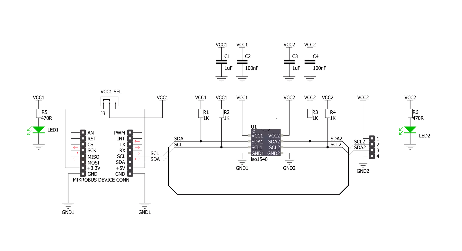
I2C Isolator Click is based on the ISO1540, a 2.5kVrms I2C digital isolator from Texas Instruments. The ISO1540 enables a completely isolated I2C interface, supporting Fast Mode Plus up to 1MHz, with two isolated bidirectional channels for clock and data lines. It provides advantages such as performance, size, and power consumption compared to optocouplers, which makes it suitable for multi-master and applications where slave clock stretching is possible. Isolated bidirectional communication is accomplished by offsetting the low-level output
voltage on the MCU side to a value greater than its high-level input voltage, preventing an internal logic latch that would occur with standard digital isolators. The ISO1540 has logic input and output buffers separated by Texas Instruments Capacitive Isolation technology using a silicon dioxide (SiO2) barrier. Also, the ISO1540 internally splits a bidirectional line into two unidirectional lines, each isolated through a single-channel digital isolator. This way, each channel output is made open-drain to comply with the open-drain technology of I2C. When used with isolated
power supplies, the ISO1540 blocks high voltages, isolates grounds, and prevents noise currents from entering the local ground and interfering with or damaging sensitive circuitry. This Click board™ can operate with either 3.3V or 5V logic voltage levels selected via the VCC1 SEL jumper. Therefore, both 3.3V and 5V capable MCUs to use the communication lines properly. The Click board™ comes equipped with a library containing easy-to-use functions and an example code that can be used, as a reference, for further development.

Features overview
Development board
Nucleo 32 with STM32F031K6 MCU board provides an affordable and flexible platform for experimenting with STM32 microcontrollers in 32-pin packages. Featuring Arduino™ Nano connectivity, it allows easy expansion with specialized shields, while being mbed-enabled for seamless integration with online resources. The
board includes an on-board ST-LINK/V2-1 debugger/programmer, supporting USB reenumeration with three interfaces: Virtual Com port, mass storage, and debug port. It offers a flexible power supply through either USB VBUS or an external source. Additionally, it includes three LEDs (LD1 for USB communication, LD2 for power,
and LD3 as a user LED) and a reset push button. The STM32 Nucleo-32 board is supported by various Integrated Development Environments (IDEs) such as IAR™, Keil®, and GCC-based IDEs like AC6 SW4STM32, making it a versatile tool for developers.

Microcontroller Overview
MCU Card / MCU

Architecture
ARM Cortex-M0
MCU Memory (KB)
32
Silicon Vendor
STMicroelectronics
Pin count
32
RAM (Bytes)
4096
You complete me!
Accessories
Click Shield for Nucleo-32 is the perfect way to expand your development board's functionalities with STM32 Nucleo-32 pinout. The Click Shield for Nucleo-32 provides two mikroBUS™ sockets to add any functionality from our ever-growing range of Click boards™. We are fully stocked with everything, from sensors and WiFi transceivers to motor control and audio amplifiers. The Click Shield for Nucleo-32 is compatible with the STM32 Nucleo-32 board, providing an affordable and flexible way for users to try out new ideas and quickly create prototypes with any STM32 microcontrollers, choosing from the various combinations of performance, power consumption, and features. The STM32 Nucleo-32 boards do not require any separate probe as they integrate the ST-LINK/V2-1 debugger/programmer and come with the STM32 comprehensive software HAL library and various packaged software examples. This development platform provides users with an effortless and common way to combine the STM32 Nucleo-32 footprint compatible board with their favorite Click boards™ in their upcoming projects.

Used MCU Pins
mikroBUS™ mapper
Take a closer look
Click board™ Schematic
Step by step
Project assembly

Start by selecting your development board and Click board™. Begin with the Nucleo 32 with STM32F031K6 MCU as your development board.


Track your results in real time
Application Output
1. Application Output - In Debug mode, the 'Application Output' window enables real-time data monitoring, offering direct insight into execution results. Ensure proper data display by configuring the environment correctly using the provided tutorial.

2. UART Terminal - Use the UART Terminal to monitor data transmission via a USB to UART converter, allowing direct communication between the Click board™ and your development system. Configure the baud rate and other serial settings according to your project's requirements to ensure proper functionality. For step-by-step setup instructions, refer to the provided tutorial.

3. Plot Output - The Plot feature offers a powerful way to visualize real-time sensor data, enabling trend analysis, debugging, and comparison of multiple data points. To set it up correctly, follow the provided tutorial, which includes a step-by-step example of using the Plot feature to display Click board™ readings. To use the Plot feature in your code, use the function: plot(*insert_graph_name*, variable_name);. This is a general format, and it is up to the user to replace 'insert_graph_name' with the actual graph name and 'variable_name' with the parameter to be displayed.

Software Support
Library Description
This library contains API for I2C Isolator Click driver.
Key functions:
i2cisolator_generic_write- Generic write functioni2cisolator_generic_read- Generic read function
Open Source
Code example
The complete application code and a ready-to-use project are available through the NECTO Studio Package Manager for direct installation in the NECTO Studio. The application code can also be found on the MIKROE GitHub account.
/*!
 * \file
 * \brief I2Cisolator Click example
 *
 * # Description
 * This is an example which demonstrates the use of I2C Isolator Click board.
 *
 * The demo application is composed of two sections :
 *
 * ## Application Init
 * Initialization driver enables - I2C,
 * sets configuration of TMP007 sensor on IrThermo 2 Click and start to write log.
 *
 * ## Application Task
 * In this example we use IrThermo 2 Click, measures the temperature with,
 * and calculate the temperature in degrees Celsius [ C ].
 * Results are being sent to the USART Terminal where you can track their changes.
 * All data logs on usb uart each second.
 *
 *
 * \author MikroE Team
 *
 */
// ------------------------------------------------------------------- INCLUDES

#include "board.h"
#include "log.h"
#include "i2cisolator.h"

/* Register Address */
#define I2CISOLATOR_IRTHERMO2_CONFIGURATION                       0x02
#define I2CISOLATOR_IRTHERMO2_OBJECT_TEMPERATURE              0x03
#define I2CISOLATOR_IRTHERMO2_STATUS_MASK_AND_ENABLE       0x05

/* Commands */
#define I2CISOLATOR_IRTHERMO2_CFG_MODEON                           0x1000
#define I2CISOLATOR_IRTHERMO2_CFG_ALERTEN                           0x0100
#define I2CISOLATOR_IRTHERMO2_CFG_TRANSC                            0x0040
#define I2CISOLATOR_IRTHERMO2_CFG_16SAMPLE                         0x0800
#define I2CISOLATOR_IRTHERMO2_STAT_ALERTEN                         0x8000
#define I2CISOLATOR_IRTHERMO2_STAT_CRTEN                            0x4000

// ------------------------------------------------------------------ VARIABLES

static i2cisolator_t i2cisolator;
static log_t logger;
static float temperature;

// ------------------------------------------------------- ADDITIONAL FUNCTIONS

void i2cisolator_get_temperature ( void )
{
    uint8_t temp_data[ 2 ];
    uint16_t temp;

    i2cisolator_generic_read( &i2cisolator, I2CISOLATOR_IRTHERMO2_OBJECT_TEMPERATURE, temp_data, 2 );

    temp = temp_data[ 0 ];
    temp <<= 8;
    temp |= temp_data[ 1 ];
    temp >>= 2;
    temperature = ( float ) temp;
    temperature *= 0.03125;
}

// ------------------------------------------------------ APPLICATION FUNCTIONS

void application_init ( void )
{
    log_cfg_t log_cfg;
    i2cisolator_cfg_t cfg;
    uint8_t tmp;

    /**
     * Logger initialization.
     * Default baud rate: 115200
     * Default log level: LOG_LEVEL_DEBUG
     * @note If USB_UART_RX and USB_UART_TX
     * are defined as HAL_PIN_NC, you will
     * need to define them manually for log to work.
     * See @b LOG_MAP_USB_UART macro definition for detailed explanation.
     */
    LOG_MAP_USB_UART( log_cfg );
    log_init( &logger, &log_cfg );
    log_info( &logger, "---- Application Init ----" );

    //  Click initialization.

    i2cisolator_cfg_setup( &cfg );
    I2CISOLATOR_MAP_MIKROBUS( cfg, MIKROBUS_1 );
    i2cisolator_init( &i2cisolator, &cfg );

    log_printf( &logger, "    Driver  Initialized\r\n" );
    log_printf( &logger, "---------------------------\r\n" );
    Delay_ms ( 100 );

    tmp =    I2CISOLATOR_IRTHERMO2_CFG_MODEON |
                I2CISOLATOR_IRTHERMO2_CFG_ALERTEN |
                I2CISOLATOR_IRTHERMO2_CFG_TRANSC |
                I2CISOLATOR_IRTHERMO2_CFG_16SAMPLE;
    i2cisolator_generic_write( &i2cisolator, I2CISOLATOR_IRTHERMO2_CONFIGURATION, &tmp, 1 );

    tmp =    I2CISOLATOR_IRTHERMO2_STAT_ALERTEN |
                I2CISOLATOR_IRTHERMO2_STAT_CRTEN;
    i2cisolator_generic_write( &i2cisolator, I2CISOLATOR_IRTHERMO2_STATUS_MASK_AND_ENABLE, &tmp, 1 );

    log_printf( &logger, "       Configuration\r\n" );
    log_printf( &logger, "      IrThermo 2 Click\r\n" );
    log_printf( &logger, "---------------------------\r\n" );
    Delay_ms ( 100 );
}

void application_task ( void )
{
    i2cisolator_get_temperature( );

    log_printf( &logger, " Temperature : %0.2f C\r\n", temperature );
    log_printf( &logger, "---------------------------\r\n" );
    Delay_ms ( 1000 );
}

int main ( void )
{
    /* Do not remove this line or clock might not be set correctly. */
    #ifdef PREINIT_SUPPORTED
    preinit();
    #endif

    application_init( );

    for ( ; ; )
    {
        application_task( );
    }

    return 0;
}


// ------------------------------------------------------------------------ END


