Set new standards in user interfaces with PCA9956B combined with STM32F031K6
24 LEDs, one encoder: Crafting masterpieces of control and style

Published Oct 01, 2024
Click board™
Knob G Click
Dev. board
Nucleo 32 with STM32F031K6 MCU
Compiler
NECTO Studio
MCU
STM32F031K6
Discover the perfect fusion of precision and visual delight with our quadrature rotary encoder boasting a vibrant ring of 24 green LEDs
A
A
Hardware Overview
How does it work?
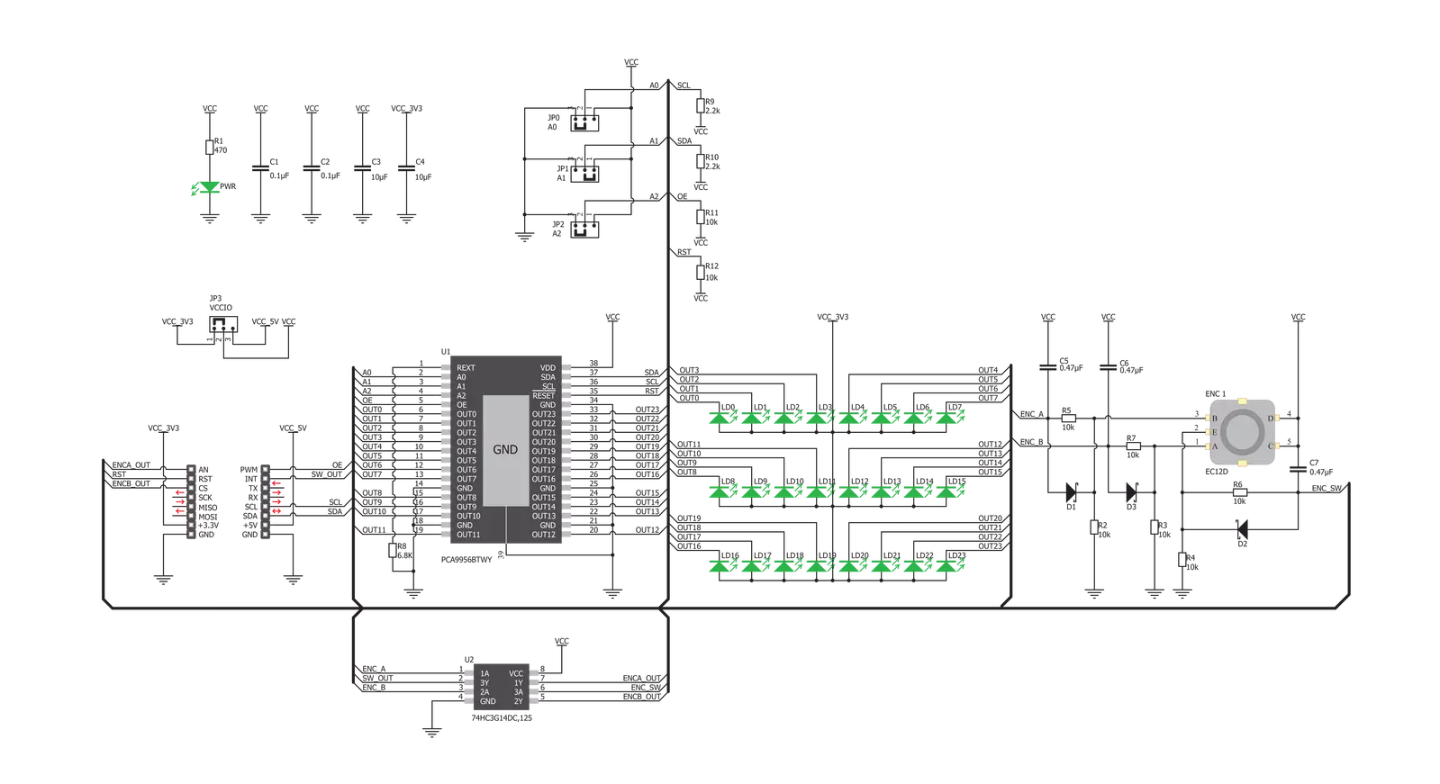
Knob G Click consists of two distinctive sections: the first section is the rotary quadrature encoder with its outputs routed to the GPIO pins of the mikroBUS. The encoder is debounced by a dedicated circuitry composed of passive elements and a triple inverting Schmitt trigger IC. The second section is the LED driver IC, with accompanying LEDs positioned in a form of a ring around the encoder, making them perfectly suited for encoder position indicators. This Click Board uses the EC12D, a 15-pulse incremental rotary encoder with a push-button, from ALPS. This encoder has very good mechanical specifications: debouncing time for its internal switches goes down to 2ms, and it can withstand a huge number of switching cycles, up to 30,000. The supporting debouncing circuitry allows contacts to fully settle before the output is triggered. When encoder contacts are closed, the capacitor will start to discharge through the resistor, via the contacts, and to the GND. The Schmitt trigger connected to the capacitor will output a LOW logic level when its low voltage threshold level is reached; and vice versa - when encoder contacts are open, the capacitor will start to charge through the resistor, and the Schmitt trigger will output a HIGH logic level, when its high voltage threshold level is reached. This allows reading the states of two encoder contacts and one push-button contact directly from the code, with no bulky software debouncing applied. This makes Knob G click usable directly within the the interrupt-on-change ISR, allowing an absolute accuracy and no skipped pulses (which might occur when a regular software polling technique is used). Output pins of the encoder contacts are labeled as ENA and ENB for the quadrature encoder contacts, and SW for the push-button contact. These pins are routed to the AN, CS, and INT pin of the Mirko BUS, respectively. The LED ring is composed of 24
individual green LEDs which are driven by the PCA9956B, an 8-bit, 24-channel, constant current LED driver, from NXP. This driver IC has many LED driving features, including constant current sinking capability, which greatly simplifies the design: maximum current through LEDs is determined by a single resistor. The PCA9956B has registers for controlling each channel individually, along with a single register which controls all channels at once. It supports PWM-mode dimming, as well as the current-mode dimming (by scaling down the maximum LED current). The PCA9956B can use a lower frequency signal from a secondary integrated PWM oscillator to modulate the PWM dimming signal. While the PWM frequency of the driver is fixed at 31.25kHz reducing the visible LED flickering completely, the modulating low-frequency signal can range from 0 to 122Hz, allowing interesting blinking effects to be produced without using the computing power of the microcontroller (MCU). The driver produces smooth dimming of LEDs, since the resolution of the PWM duty cycle is 8 bits. More details and features can be found found in the PCA9956B datasheet, in the download section, below. The OE pin of the PCA9956B is routed to the PWM pin of the mikroBUS. When a LOW logic level is applied to the OE pin, LED outputs will be enabled. This pin is pulled to a HIGH logic level by a resistor. The OE pin can also be driven by an external PWM signal, offering an alternative way of dimming all LEDs at once. LED driver IC can be reset by pulling the RST pin to a LOW logic level. This pin is pulled to a HIGH level by the resistor. The reset pulse can be very short (2.5 µs) but the device will not be ready for another 1.5 ms after the pulse. Besides the hardware reset, the PCA9956B also supports a software reset, which is required if the device is going to be operated in the fast I2C mode (including clock speed above 100kHz).
The datasheet of the PCA9956B offers a detailed explanation on performing the software reset and using the fast I2C mode (FM+). The PCA9956B IC uses the 3.3V rail of the mikroBUS as the LED power supply, so there is no significant voltage drop causing thermal dissipation. However, turning all LEDs ON at once with the maximum current set in the current registers, might cause the Knob G click to dissipate some heat. This is expected, as the thermal dissipation of each channel is adding up to the sum dissipation of the entire IC. The PCA9956B IC features thermal shutdown protection, along with the set of error reporting features. The PCA9956B can report both open-circuit event and short-circuit event for each LED. These errors will be written in the ERR registers, one for each LED channel. The datasheet explains how to interpret the values of these registers. Slave I2C address of the PCA9956B device can be selected by using three SMD jumpers, grouped under the ADDR label. The PCA9956B allows its slave I2C address to be selected from a wide range of 125 different values. Each of the address pins (A0 to A3) can be left floating, pulled up, pulled down and shorted to VCC or GND. However, some I2C addresses are reserved, so they should be used with care. The datasheet of the PCA9956B offers tables with resistor values for each state of the address pins and reserved I2C addresses. Knob G click uses three 0 Ω SMD jumpers to set the states of these address pins. The logic voltage level can be selected by the SMD jumper, labeled as VCCIO. This jumper determines levels for the logic signals from Schmitt triggers, as well as for the I2C interface of Knob G click. This allows it to be interfaced with a wide range of different MCUs, both compatible with 3.3V and 5V logic voltage levels.


Features overview
Development board
Nucleo 32 with STM32F031K6 MCU board provides an affordable and flexible platform for experimenting with STM32 microcontrollers in 32-pin packages. Featuring Arduino™ Nano connectivity, it allows easy expansion with specialized shields, while being mbed-enabled for seamless integration with online resources. The
board includes an on-board ST-LINK/V2-1 debugger/programmer, supporting USB reenumeration with three interfaces: Virtual Com port, mass storage, and debug port. It offers a flexible power supply through either USB VBUS or an external source. Additionally, it includes three LEDs (LD1 for USB communication, LD2 for power,
and LD3 as a user LED) and a reset push button. The STM32 Nucleo-32 board is supported by various Integrated Development Environments (IDEs) such as IAR™, Keil®, and GCC-based IDEs like AC6 SW4STM32, making it a versatile tool for developers.

Microcontroller Overview
MCU Card / MCU

Architecture
ARM Cortex-M0
MCU Memory (KB)
32
Silicon Vendor
STMicroelectronics
Pin count
32
RAM (Bytes)
4096
You complete me!
Accessories
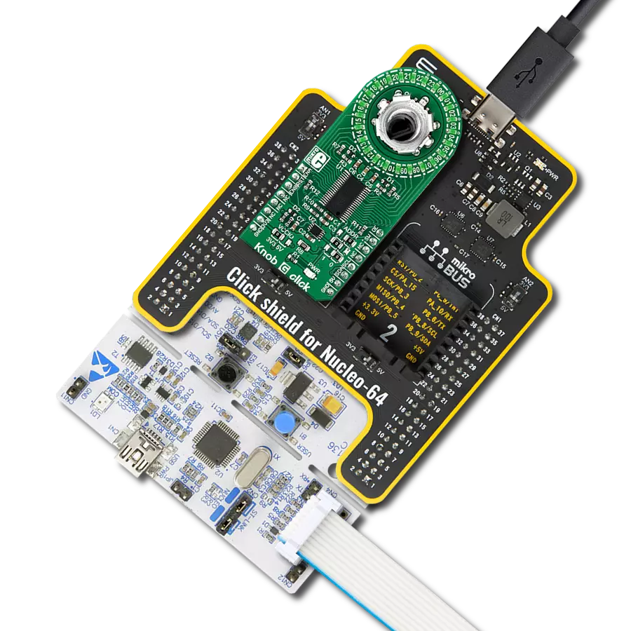
Click Shield for Nucleo-32 is the perfect way to expand your development board's functionalities with STM32 Nucleo-32 pinout. The Click Shield for Nucleo-32 provides two mikroBUS™ sockets to add any functionality from our ever-growing range of Click boards™. We are fully stocked with everything, from sensors and WiFi transceivers to motor control and audio amplifiers. The Click Shield for Nucleo-32 is compatible with the STM32 Nucleo-32 board, providing an affordable and flexible way for users to try out new ideas and quickly create prototypes with any STM32 microcontrollers, choosing from the various combinations of performance, power consumption, and features. The STM32 Nucleo-32 boards do not require any separate probe as they integrate the ST-LINK/V2-1 debugger/programmer and come with the STM32 comprehensive software HAL library and various packaged software examples. This development platform provides users with an effortless and common way to combine the STM32 Nucleo-32 footprint compatible board with their favorite Click boards™ in their upcoming projects.

Used MCU Pins
mikroBUS™ mapper
Take a closer look
Click board™ Schematic
Step by step
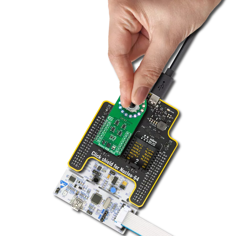
Project assembly

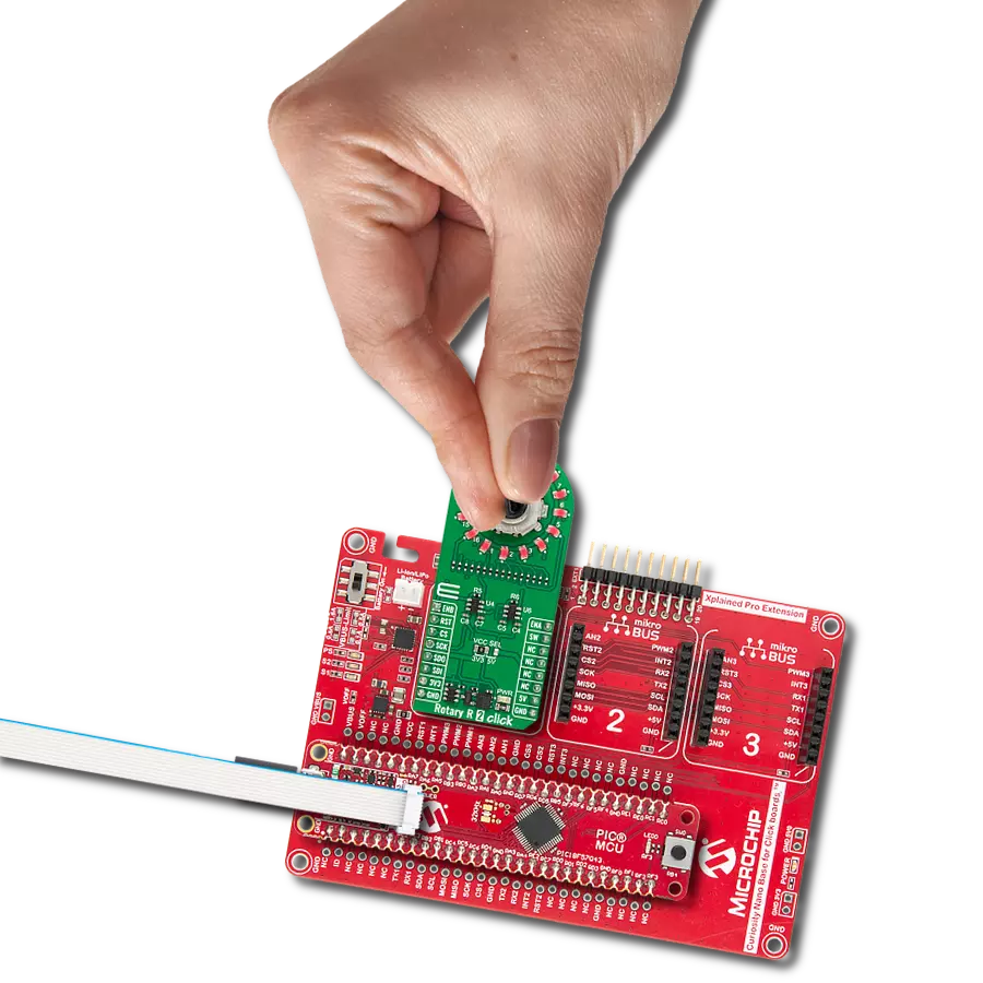
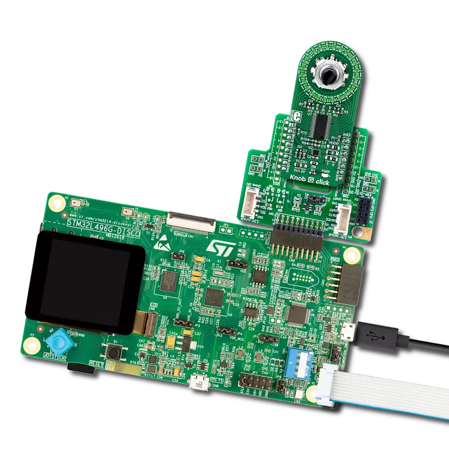
Start by selecting your development board and Click board™. Begin with the Nucleo 32 with STM32F031K6 MCU as your development board.


Track your results in real time
Application Output
1. Application Output - In Debug mode, the 'Application Output' window enables real-time data monitoring, offering direct insight into execution results. Ensure proper data display by configuring the environment correctly using the provided tutorial.

2. UART Terminal - Use the UART Terminal to monitor data transmission via a USB to UART converter, allowing direct communication between the Click board™ and your development system. Configure the baud rate and other serial settings according to your project's requirements to ensure proper functionality. For step-by-step setup instructions, refer to the provided tutorial.

3. Plot Output - The Plot feature offers a powerful way to visualize real-time sensor data, enabling trend analysis, debugging, and comparison of multiple data points. To set it up correctly, follow the provided tutorial, which includes a step-by-step example of using the Plot feature to display Click board™ readings. To use the Plot feature in your code, use the function: plot(*insert_graph_name*, variable_name);. This is a general format, and it is up to the user to replace 'insert_graph_name' with the actual graph name and 'variable_name' with the parameter to be displayed.

Software Support
Library Description
This library contains API for Knob G Click driver.
Key functions:
knob_get_encoder_position- Functions for get Encoder positionknob_set_led_state- Functions for set led state(PWM on the LED)knob_get_sw_button_state- Functions for get SW pin(switch button) state
Open Source
Code example
The complete application code and a ready-to-use project are available through the NECTO Studio Package Manager for direct installation in the NECTO Studio. The application code can also be found on the MIKROE GitHub account.
/*!
 * \file
 * \brief Knob Click example
 *
 * # Description
 * The demo application displays different types of LED controls and encoder position readings.
 *
 * The demo application is composed of two sections :
 *
 * ## Application Init
 * Configuring Clicks and log objects.
 * Settings the Click in the default configuration.
 *
 * ## Application Task
 * The Task application has 3 test modes:
 *  - The first example is setting BRIGHTNESS on all LEDs.
 *  - Other examples put the LED in the position read from the encoder.
 *  - The third example sets the LED to be read while the encoder registers the clockwise movement
 *    and turn off those LEDs that the encoder reads when moving in a counterclockwise direction.
 *  - The example is changed by pressing the SW button
 *
 * \author Katarina Perendic
 *
 */
// ------------------------------------------------------------------- INCLUDES

#include "board.h"
#include "log.h"
#include "knob.h"

// ------------------------------------------------------------------ VARIABLES

static knob_t knob;
static log_t logger;

static int32_t new_position = 0;
static int32_t old_position = 0;
static uint8_t sw_state = 0;

// ------------------------------------------------------ APPLICATION FUNCTIONS

void application_init ( void )
{
    log_cfg_t log_cfg;
    knob_cfg_t cfg;

    /**
     * Logger initialization.
     * Default baud rate: 115200
     * Default log level: LOG_LEVEL_DEBUG
     * @note If USB_UART_RX and USB_UART_TX
     * are defined as HAL_PIN_NC, you will
     * need to define them manually for log to work.
     * See @b LOG_MAP_USB_UART macro definition for detailed explanation.
     */
    LOG_MAP_USB_UART( log_cfg );
    log_init( &logger, &log_cfg );
    log_info( &logger, "---- Application Init ----" );

    //  Click initialization.

    knob_cfg_setup( &cfg );
    KNOB_MAP_MIKROBUS( cfg, MIKROBUS_1 );
    knob_init( &knob, &cfg );

    knob_reset( &knob );
    Delay_ms ( 300 );

    knob_default_cfg( &knob );
}

void application_task ( void )
{
    uint8_t cnt;
    uint8_t direction;

    //  Task implementation.

    knob_get_encoder_position( &knob, &new_position, &direction );

    if ( knob_get_sw_button_state( &knob ) == 0 )
    {
        sw_state++;
        if ( sw_state >= 3 ) sw_state = 0;

        knob_set_brightness( &knob, KNOB_BRIGHTNESS_ALL_LED, 0x00 );
        Delay_ms ( 300 );
    }

    // Logs position

    if ( new_position != old_position )
    {
        log_printf( &logger, "** EnCoder position : %d ", new_position );
    }
    old_position = new_position;

    switch ( sw_state )
    {
        // Brightness

        case 0:
        {
            cnt++;
            if ( cnt > 127 )
            {
                cnt = 0;
            }
            knob_set_brightness( &knob, KNOB_BRIGHTNESS_ALL_LED, cnt );
            Delay_ms ( 15 );

            break;
        }

        // Encoder with one led

        case 1:
        {
            if ( new_position > 24 )
            {
                knob_set_encoder_start_position( &knob, 1 );
            }
            if ( new_position < 1 )
            {
                knob_set_encoder_start_position( &knob, 24 );
            }

            if (direction == 1)
            {
                knob_set_led_state( &knob, new_position, KNOB_LED_ON );
                knob_set_led_state( &knob, new_position - 1, KNOB_LED_OFF );
            }
            else
            {
                knob_set_led_state( &knob, new_position, KNOB_LED_ON );
                knob_set_led_state( &knob, new_position + 1, KNOB_LED_OFF );
            }
            Delay_1ms();
            break;
        }

        // Encoder with all led

        case 2:
        {
            if ( new_position > 24 )
            {
                knob_set_encoder_start_position( &knob, 1 );
            }
            if ( new_position < 1 )
            {
                knob_set_encoder_start_position( &knob, 24 );
            }

            if ( direction == 1 )
            {
                knob_set_led_state( &knob, new_position, KNOB_LED_ON );
            }
            else
            {
                knob_set_led_state( &knob, new_position + 1, KNOB_LED_OFF);
            }
            Delay_1ms();
            break;
        }
    }
}

int main ( void )
{
    /* Do not remove this line or clock might not be set correctly. */
    #ifdef PREINIT_SUPPORTED
    preinit();
    #endif

    application_init( );

    for ( ; ; )
    {
        application_task( );
    }

    return 0;
}


// ------------------------------------------------------------------------ END
Additional Support
Resources
Category:Rotary encoder