Detect the press of an inductive touch button using LDC3114 and STM32F031K6
Inductive sensing

Published Oct 01, 2024
Click board™
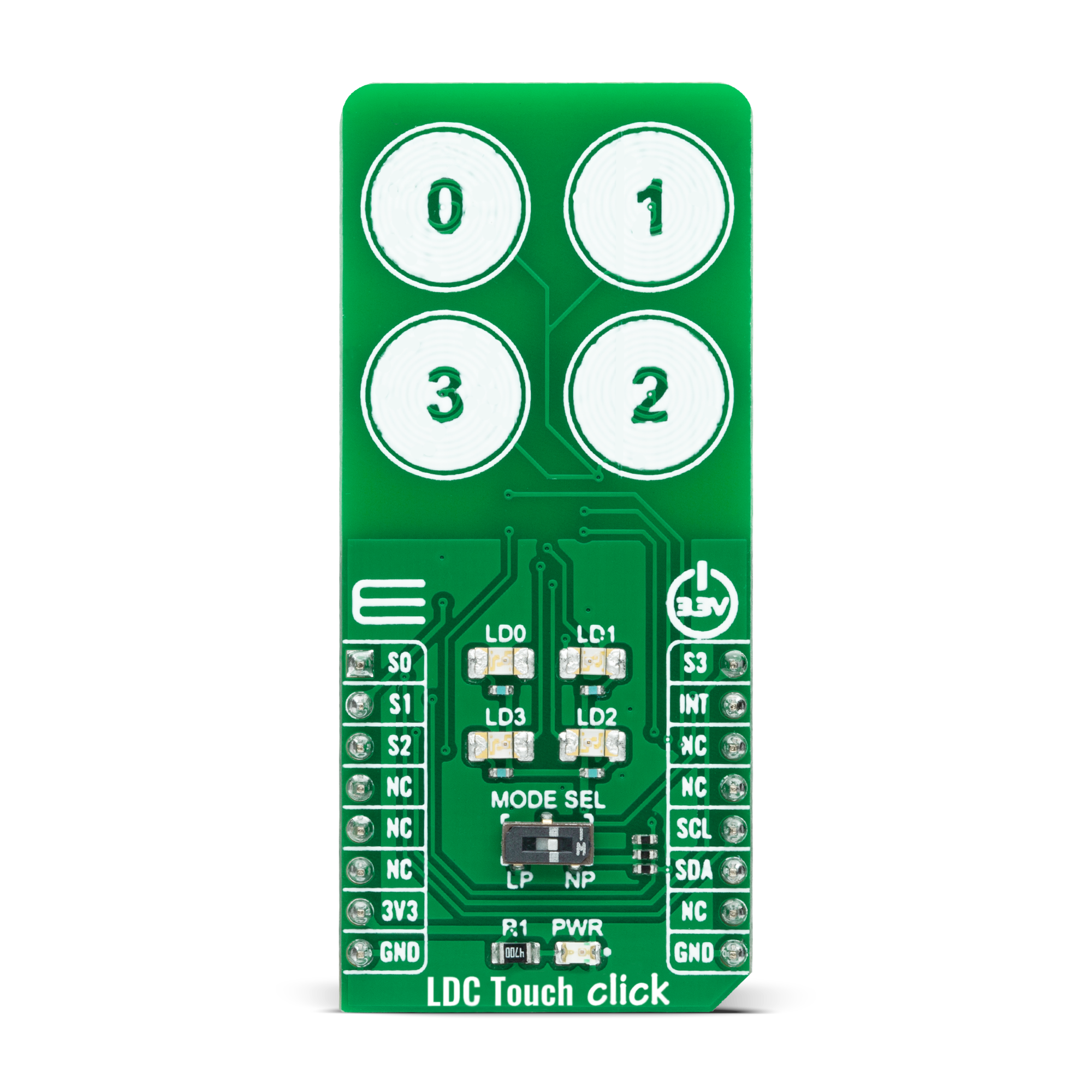
LDC Touch Click
Dev. board
Nucleo 32 with STM32F031K6 MCU
Compiler
NECTO Studio
MCU
STM32F031K6
Sense the presence and position of a conductive target object
A
A
Hardware Overview
How does it work?
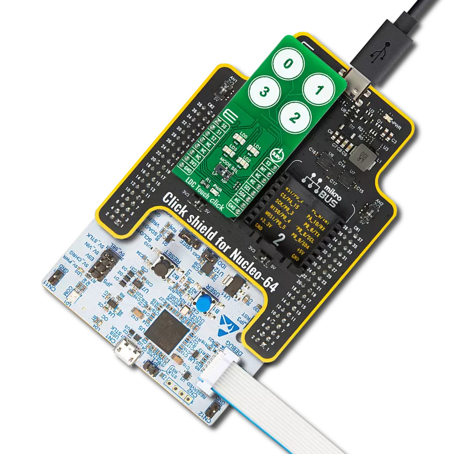
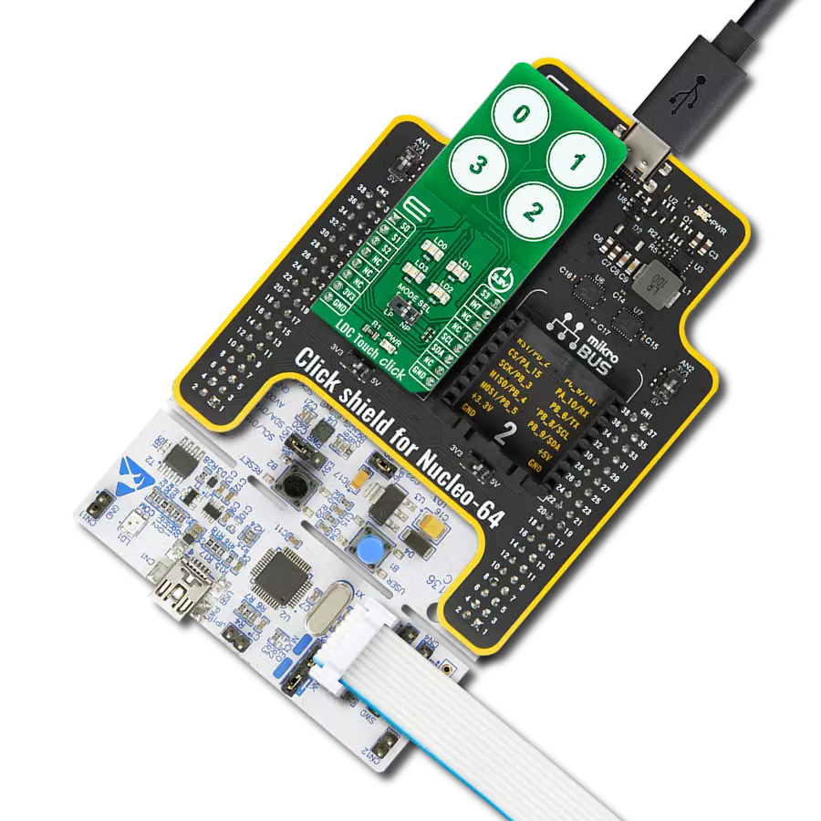
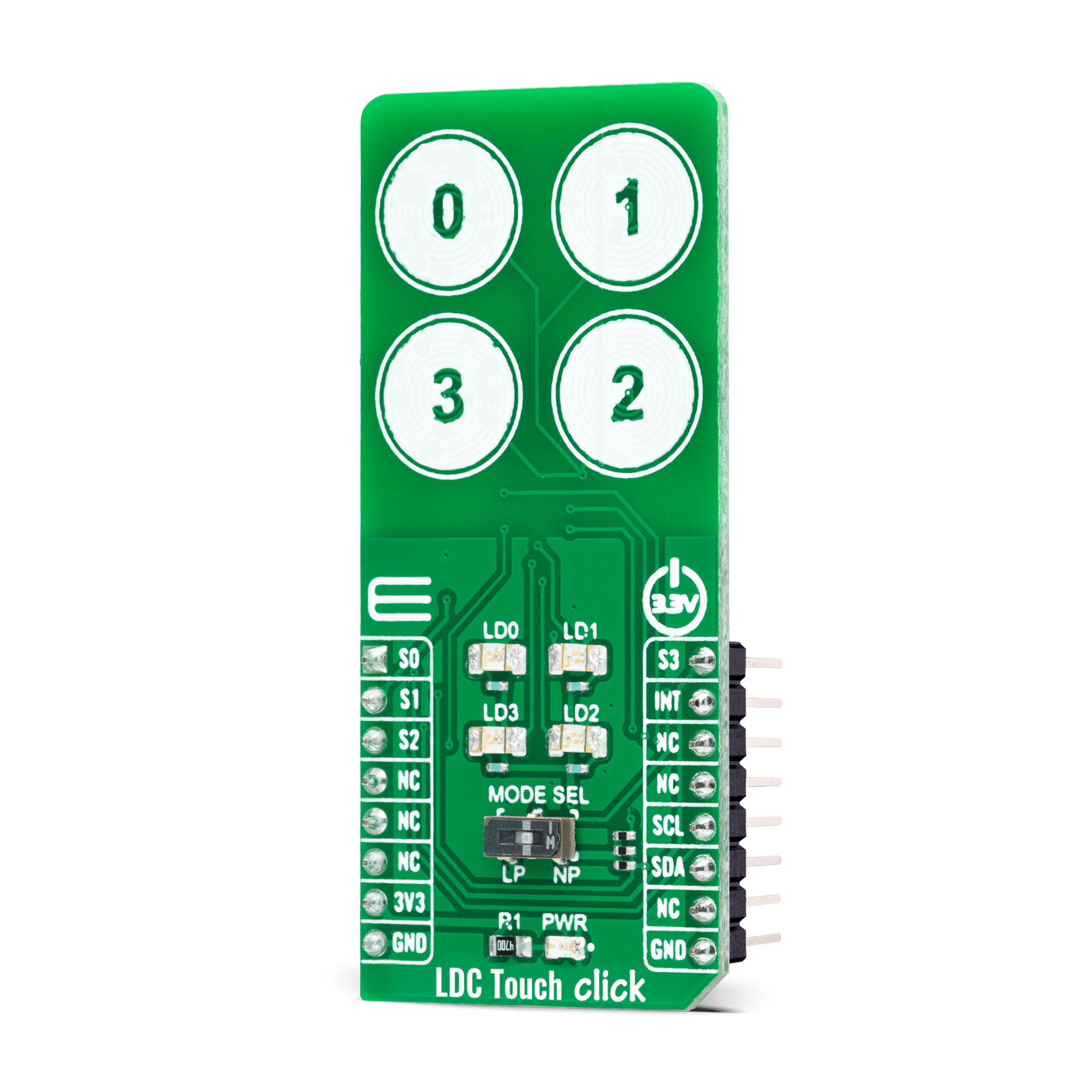
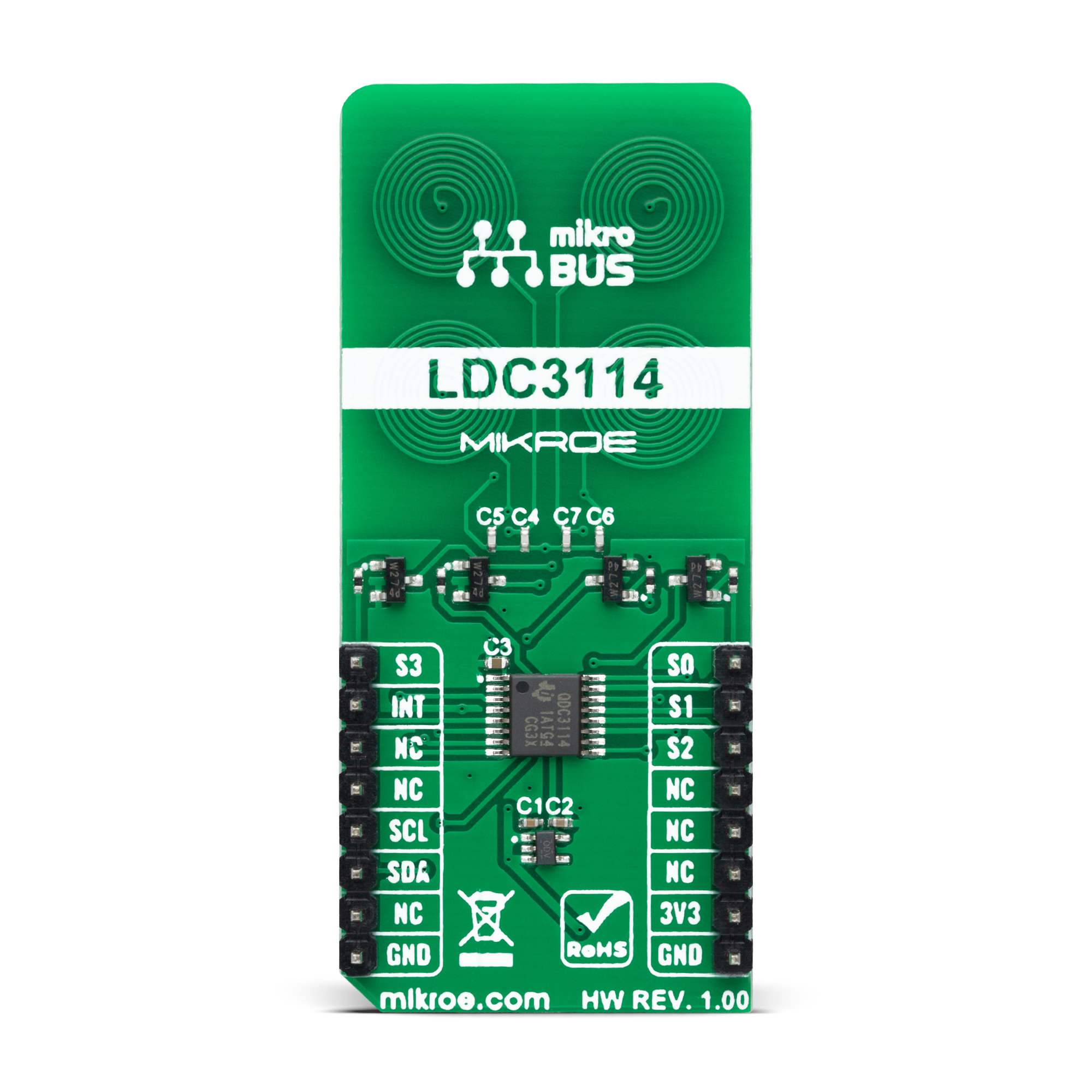
LDC Touch Click is based on the LDC3114-Q1, a hybrid multichannel, high-resolution inductance-to-digital converter from Texas Instruments. This inductive sensing device enables touch button design for a human-machine interface (HMI) by measuring small deflections of conductive targets using a coil implemented on a printed circuit board. Button presses form micro-deflection in the conductive targets, which cause frequency shifts in the resonant sensors, and measures such frequency shifts determining when button press occurs. With adjustable sensitivity per input channel, the LDC3114-Q1 can reliably operate with a wide range of physical button structures and materials. The LDC3114-Q1 offers two main modes of operations: raw data access mode and button algorithm mode, which is controlled by register settings. The button mode can automatically correct any deformation in the conductive targets and offers well-matched channels allowing for differential and ratiometric measurements, which enable compensation of environmental and aging conditions
such as temperature and mechanical drift. On the other hand, it also implements a raw data access mode, where MCU can directly read the data representing the effective inductance of the sensor and implement further post-processing. This Click board™ communicates with MCU using the standard I2C 2-Wire interface to read data and configure settings, supporting a Fast Mode operation up to 400kHz. Also, the LDC3114-Q1 requires a voltage of 1.8V for its power supply to work correctly. Therefore, a small regulating LDO, the TLV700, provides a 1.8V out of 3V3 mikroBUS™ power rail. As mentioned earlier, this board contains four touch buttons, representing the only elements on the upper-top side of the board. Each button has its own LED indicator representing the activity in that field. If a touch event is detected on one of these onboard pads, the state of the corresponding LED will be changed, indicating an activated channel; more precisely, touch has been detected on that specific field. Alongside LED indicators, data from these channels can be
processed via the MCU through four pins labeled from S0 to S3, routed to the AN, RST, CS, and PWM pins of the mikroBUS™ socket, respectively. Besides, an additional interrupt signal is routed on the INT pin of the mikroBUS™ socket, indicating when a specific interrupt event occurs (touch detection, available new data, and more) alongside two power modes of operation. A Normal Power Mode for active sampling at 10, 20, 40, or 80SPS, and a Low Power Mode for reduced current consumption at 0.625, 1.25, 2.5, or 5SPS selectable through an onboard switch labeled as MODE SEL. This Click board™ can only be operated from a 3.3V logic voltage level. Therefore, the board must perform appropriate logic voltage conversion before using MCUs with different logic levels. However, the Click board™ comes equipped with a library containing functions and an example code that can be used as a reference for further development.
Features overview
Development board
Nucleo 32 with STM32F031K6 MCU board provides an affordable and flexible platform for experimenting with STM32 microcontrollers in 32-pin packages. Featuring Arduino™ Nano connectivity, it allows easy expansion with specialized shields, while being mbed-enabled for seamless integration with online resources. The
board includes an on-board ST-LINK/V2-1 debugger/programmer, supporting USB reenumeration with three interfaces: Virtual Com port, mass storage, and debug port. It offers a flexible power supply through either USB VBUS or an external source. Additionally, it includes three LEDs (LD1 for USB communication, LD2 for power,
and LD3 as a user LED) and a reset push button. The STM32 Nucleo-32 board is supported by various Integrated Development Environments (IDEs) such as IAR™, Keil®, and GCC-based IDEs like AC6 SW4STM32, making it a versatile tool for developers.

Microcontroller Overview
MCU Card / MCU

Architecture
ARM Cortex-M0
MCU Memory (KB)
32
Silicon Vendor
STMicroelectronics
Pin count
32
RAM (Bytes)
4096
You complete me!
Accessories
Click Shield for Nucleo-32 is the perfect way to expand your development board's functionalities with STM32 Nucleo-32 pinout. The Click Shield for Nucleo-32 provides two mikroBUS™ sockets to add any functionality from our ever-growing range of Click boards™. We are fully stocked with everything, from sensors and WiFi transceivers to motor control and audio amplifiers. The Click Shield for Nucleo-32 is compatible with the STM32 Nucleo-32 board, providing an affordable and flexible way for users to try out new ideas and quickly create prototypes with any STM32 microcontrollers, choosing from the various combinations of performance, power consumption, and features. The STM32 Nucleo-32 boards do not require any separate probe as they integrate the ST-LINK/V2-1 debugger/programmer and come with the STM32 comprehensive software HAL library and various packaged software examples. This development platform provides users with an effortless and common way to combine the STM32 Nucleo-32 footprint compatible board with their favorite Click boards™ in their upcoming projects.

Used MCU Pins
mikroBUS™ mapper
Take a closer look
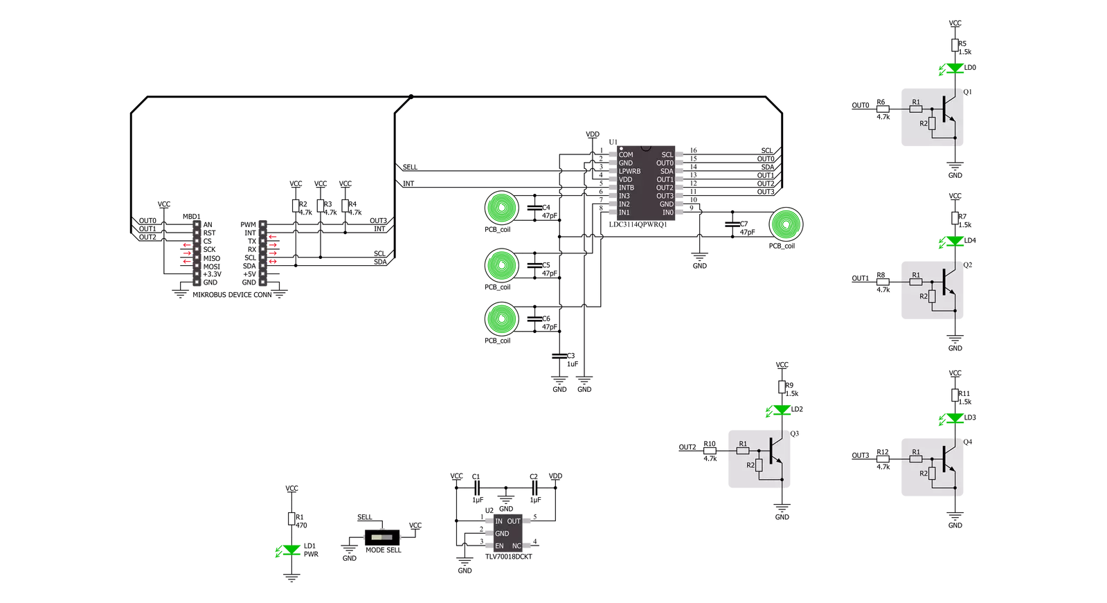
Click board™ Schematic
Step by step
Project assembly

Start by selecting your development board and Click board™. Begin with the Nucleo 32 with STM32F031K6 MCU as your development board.


Track your results in real time
Application Output
1. Application Output - In Debug mode, the 'Application Output' window enables real-time data monitoring, offering direct insight into execution results. Ensure proper data display by configuring the environment correctly using the provided tutorial.

2. UART Terminal - Use the UART Terminal to monitor data transmission via a USB to UART converter, allowing direct communication between the Click board™ and your development system. Configure the baud rate and other serial settings according to your project's requirements to ensure proper functionality. For step-by-step setup instructions, refer to the provided tutorial.

3. Plot Output - The Plot feature offers a powerful way to visualize real-time sensor data, enabling trend analysis, debugging, and comparison of multiple data points. To set it up correctly, follow the provided tutorial, which includes a step-by-step example of using the Plot feature to display Click board™ readings. To use the Plot feature in your code, use the function: plot(*insert_graph_name*, variable_name);. This is a general format, and it is up to the user to replace 'insert_graph_name' with the actual graph name and 'variable_name' with the parameter to be displayed.

Software Support
Library Description
This library contains API for LDC Touch Click driver.
Key functions:
ldctouch_get_int_pinThis function returns the INT pin logic state.ldctouch_get_dataThis function reads status, out_state, and all buttons raw data.ldctouch_set_operation_modeThis function sets the operation mode.
Open Source
Code example
The complete application code and a ready-to-use project are available through the NECTO Studio Package Manager for direct installation in the NECTO Studio. The application code can also be found on the MIKROE GitHub account.
/*!
 * @file main.c
 * @brief LDCTouch Click example
 *
 * # Description
 * This example demonstrates the use of LDC Touch Click board by configuring
 * the buttons to trigger on finger press, and reading the buttons state in the loop.
 *
 * The demo application is composed of two sections :
 *
 * ## Application Init
 * Initializes the driver and configures the buttons to be active on finger press.
 *
 * ## Application Task
 * Waits for the button active event interrupt and then reads and displays the buttons
 * state and their raw data on the USB UART every 200ms approximately.
 *
 * @author Stefan Filipovic
 *
 */

#include "board.h"
#include "log.h"
#include "ldctouch.h"

static ldctouch_t ldctouch;
static log_t logger;

void application_init ( void )
{
    log_cfg_t log_cfg;  /**< Logger config object. */
    ldctouch_cfg_t ldctouch_cfg;  /**< Click config object. */

    /**
     * Logger initialization.
     * Default baud rate: 115200
     * Default log level: LOG_LEVEL_DEBUG
     * @note If USB_UART_RX and USB_UART_TX
     * are defined as HAL_PIN_NC, you will
     * need to define them manually for log to work.
     * See @b LOG_MAP_USB_UART macro definition for detailed explanation.
     */
    LOG_MAP_USB_UART( log_cfg );
    log_init( &logger, &log_cfg );
    log_info( &logger, " Application Init " );

    // Click initialization.
    ldctouch_cfg_setup( &ldctouch_cfg );
    LDCTOUCH_MAP_MIKROBUS( ldctouch_cfg, MIKROBUS_1 );
    if ( I2C_MASTER_ERROR == ldctouch_init( &ldctouch, &ldctouch_cfg ) )
    {
        log_error( &logger, " Communication init." );
        for ( ; ; );
    }

    if ( LDCTOUCH_ERROR == ldctouch_default_cfg ( &ldctouch ) )
    {
        log_error( &logger, " Default configuration." );
        for ( ; ; );
    }

    log_info( &logger, " Application Task " );
}

void application_task ( void )
{
    static bool button_active = true;
    if ( !ldctouch_get_int_pin ( &ldctouch ) )
    {
        ldctouch_data_t button_data;
        if ( LDCTOUCH_OK == ldctouch_get_data ( &ldctouch, &button_data ) )
        {
            button_active = true;
            log_printf ( &logger, " Active button: -" );
            for ( uint8_t cnt = 0; cnt < 4; cnt++ )
            {
                if ( button_data.out_state & ( 1 << cnt ) )
                {
                    log_printf ( &logger, " %u - ", ( uint16_t ) cnt );
                }
            }
            log_printf ( &logger, "\r\n Button 0 raw data: %d\r\n", button_data.ch0_raw_button );
            log_printf ( &logger, " Button 1 raw data: %d\r\n", button_data.ch1_raw_button );
            log_printf ( &logger, " Button 2 raw data: %d\r\n", button_data.ch2_raw_button );
            log_printf ( &logger, " Button 3 raw data: %d\r\n\n", button_data.ch3_raw_button );
            Delay_ms ( 200 );
        }
    }
    else
    {
        if ( button_active )
        {
            button_active = false;
            log_printf ( &logger, " Active button: - none -\r\n" );
        }
    }
}

int main ( void )
{
    /* Do not remove this line or clock might not be set correctly. */
    #ifdef PREINIT_SUPPORTED
    preinit();
    #endif

    application_init( );

    for ( ; ; )
    {
        application_task( );
    }

    return 0;
}

// ------------------------------------------------------------------------ END