Take your sound to the next level with SSM2167-1RMZ-R7 and STM32F031K6
Speak up, make an impact

Published Oct 01, 2024
Click board™
MIC 3 Click
Dev. board
Nucleo 32 with STM32F031K6 MCU
Compiler
NECTO Studio
MCU
STM32F031K6
Unleash your creativity and achieve unparalleled sound clarity with our guide to building microphone system
A
A
Hardware Overview
How does it work?
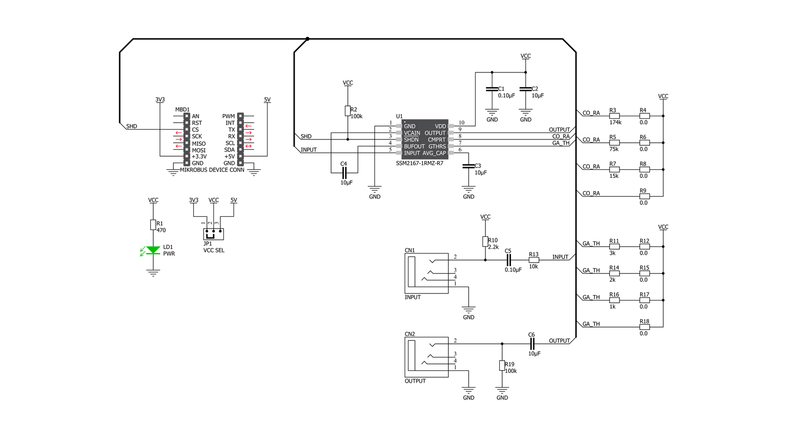
MIC 3 Click is based on the SSM2167-1RMZ-R7 from Analog Devices, a complete and flexible solution for conditioning microphone inputs in personal electronics and computer audio systems. The Click board™ is also excellent for improving vocal clarity in communications and public address systems. A low noise voltage-controlled amplifier (VCA) provides a gain that is dynamically adjusted by a control loop to maintain a set compression characteristic. The MIC 3 Click provides two operation settings, these settings are selectable with NOISE G. COMPR. jumpers. The MIC 3 Click
provides four different preset values of the noise gate threshold. Experiment with these values by varying the gate. The noise gate threshold is a programmable point using an external resistor. The downward expansion threshold may be set between −40 dBV and −55 dBV. The Click board™ provides four different preset values of the compression ratio. Changing the scaling of the control signal fed to the VCA causes a change in the circuit compression ratio.Lowering RCOMP gives smaller compression ratios. Automatic Gain Control (AGC) performance is achieved with
compression ratios between 2:1 and 10:1, and is dependent on the application. Shorting RCOMP disables the AGC function, setting the compression equal to 1:1. This Click board™ can operate with either 3.3V or 5V logic voltage levels selected via the VCC SEL jumper. This way, both 3.3V and 5V capable MCUs can use the communication lines properly. Also, this Click board™ comes equipped with a library containing easy-to-use functions and an example code that can be used as a reference for further development.

Features overview
Development board
Nucleo 32 with STM32F031K6 MCU board provides an affordable and flexible platform for experimenting with STM32 microcontrollers in 32-pin packages. Featuring Arduino™ Nano connectivity, it allows easy expansion with specialized shields, while being mbed-enabled for seamless integration with online resources. The
board includes an on-board ST-LINK/V2-1 debugger/programmer, supporting USB reenumeration with three interfaces: Virtual Com port, mass storage, and debug port. It offers a flexible power supply through either USB VBUS or an external source. Additionally, it includes three LEDs (LD1 for USB communication, LD2 for power,
and LD3 as a user LED) and a reset push button. The STM32 Nucleo-32 board is supported by various Integrated Development Environments (IDEs) such as IAR™, Keil®, and GCC-based IDEs like AC6 SW4STM32, making it a versatile tool for developers.

Microcontroller Overview
MCU Card / MCU

Architecture
ARM Cortex-M0
MCU Memory (KB)
32
Silicon Vendor
STMicroelectronics
Pin count
32
RAM (Bytes)
4096
You complete me!
Accessories
Click Shield for Nucleo-32 is the perfect way to expand your development board's functionalities with STM32 Nucleo-32 pinout. The Click Shield for Nucleo-32 provides two mikroBUS™ sockets to add any functionality from our ever-growing range of Click boards™. We are fully stocked with everything, from sensors and WiFi transceivers to motor control and audio amplifiers. The Click Shield for Nucleo-32 is compatible with the STM32 Nucleo-32 board, providing an affordable and flexible way for users to try out new ideas and quickly create prototypes with any STM32 microcontrollers, choosing from the various combinations of performance, power consumption, and features. The STM32 Nucleo-32 boards do not require any separate probe as they integrate the ST-LINK/V2-1 debugger/programmer and come with the STM32 comprehensive software HAL library and various packaged software examples. This development platform provides users with an effortless and common way to combine the STM32 Nucleo-32 footprint compatible board with their favorite Click boards™ in their upcoming projects.

Used MCU Pins
mikroBUS™ mapper
Take a closer look
Click board™ Schematic
Step by step
Project assembly

Start by selecting your development board and Click board™. Begin with the Nucleo 32 with STM32F031K6 MCU as your development board.


Track your results in real time
Application Output
1. Application Output - In Debug mode, the 'Application Output' window enables real-time data monitoring, offering direct insight into execution results. Ensure proper data display by configuring the environment correctly using the provided tutorial.

2. UART Terminal - Use the UART Terminal to monitor data transmission via a USB to UART converter, allowing direct communication between the Click board™ and your development system. Configure the baud rate and other serial settings according to your project's requirements to ensure proper functionality. For step-by-step setup instructions, refer to the provided tutorial.

3. Plot Output - The Plot feature offers a powerful way to visualize real-time sensor data, enabling trend analysis, debugging, and comparison of multiple data points. To set it up correctly, follow the provided tutorial, which includes a step-by-step example of using the Plot feature to display Click board™ readings. To use the Plot feature in your code, use the function: plot(*insert_graph_name*, variable_name);. This is a general format, and it is up to the user to replace 'insert_graph_name' with the actual graph name and 'variable_name' with the parameter to be displayed.

Software Support
Library Description
This library contains API for MIC 3 Click driver.
Key functions:
mic3_shd_pin_set- MIC 3 SHD pin setting function.
Open Source
Code example
The complete application code and a ready-to-use project are available through the NECTO Studio Package Manager for direct installation in the NECTO Studio. The application code can also be found on the MIKROE GitHub account.
/*!
 * @file main.c
 * @brief MIC 3 Click Example.
 *
 * # Description
 * This is an example that demonstrates the use of the MIC 3 Click board.
 *
 * The demo application is composed of two sections :
 *
 * ## Application Init
 * Initialization of SHD to output and log module, maping GPIO for Mikrobus1, and seting SHD pin to
 * HIGH state.
 *
 * ## Application Task
 * Turning microphone on for the 5 seconds, then turning it off for 5 seconds.
 *
 * @author Stefan Ilic
 *
 */

#include "board.h"
#include "log.h"
#include "mic3.h"

static mic3_t mic3;   /**< MIC 3 Click driver object. */
static log_t logger;    /**< Logger object. */

void application_init ( void )
{
    log_cfg_t log_cfg;  /**< Logger config object. */
    mic3_cfg_t mic3_cfg;  /**< Click config object. */

    /**
     * Logger initialization.
     * Default baud rate: 115200
     * Default log level: LOG_LEVEL_DEBUG
     * @note If USB_UART_RX and USB_UART_TX
     * are defined as HAL_PIN_NC, you will
     * need to define them manually for log to work.
     * See @b LOG_MAP_USB_UART macro definition for detailed explanation.
     */
    LOG_MAP_USB_UART( log_cfg );
    log_init( &logger, &log_cfg );
    log_info( &logger, " Application Init " );

    // Click initialization.
    mic3_cfg_setup( &mic3_cfg );
    MIC3_MAP_MIKROBUS( mic3_cfg, MIKROBUS_1 );
    if ( DIGITAL_OUT_UNSUPPORTED_PIN == mic3_init( &mic3, &mic3_cfg ) ) {
        log_error( &logger, " Application Init Error. " );
        log_info( &logger, " Please, run program again... " );

        for ( ; ; );
    }
    mic3_default_cfg ( &mic3 );
    log_info( &logger, " Application Task " );
}

void application_task ( void )
{
    log_printf( &logger, " - Microphone is turned on  - \r\n" );
    mic3_shd_pin_set( &mic3, MIC3_PIN_STATE_HIGH );
    Delay_ms ( 1000 );
    Delay_ms ( 1000 );
    Delay_ms ( 1000 );
    Delay_ms ( 1000 );
    Delay_ms ( 1000 );

    log_printf( &logger, " - Microphone is turned off  - \r\n" );
    mic3_shd_pin_set( &mic3, MIC3_PIN_STATE_LOW );
    Delay_ms ( 1000 );
    Delay_ms ( 1000 );
    Delay_ms ( 1000 );
    Delay_ms ( 1000 );
    Delay_ms ( 1000 );
}

int main ( void )
{
    /* Do not remove this line or clock might not be set correctly. */
    #ifdef PREINIT_SUPPORTED
    preinit();
    #endif

    application_init( );

    for ( ; ; )
    {
        application_task( );
    }

    return 0;
}

// ------------------------------------------------------------------------ END


