Maximize your data transmission capabilities with EMB-LR1276S and STM32F031K6
Reaching new horizons with 868MHz long-range transceivers
Published Oct 01, 2024
Click board™
Nano LR Click
Dev. board
Nucleo 32 with STM32F031K6 MCU
Compiler
NECTO Studio
MCU
STM32F031K6
Our 868MHz long-range transceiver is meticulously engineered to extend the reach of your wireless communication, allowing you to collect and transmit critical data from remote and challenging locations with unmatched reliability.
A
A
Hardware Overview
How does it work?
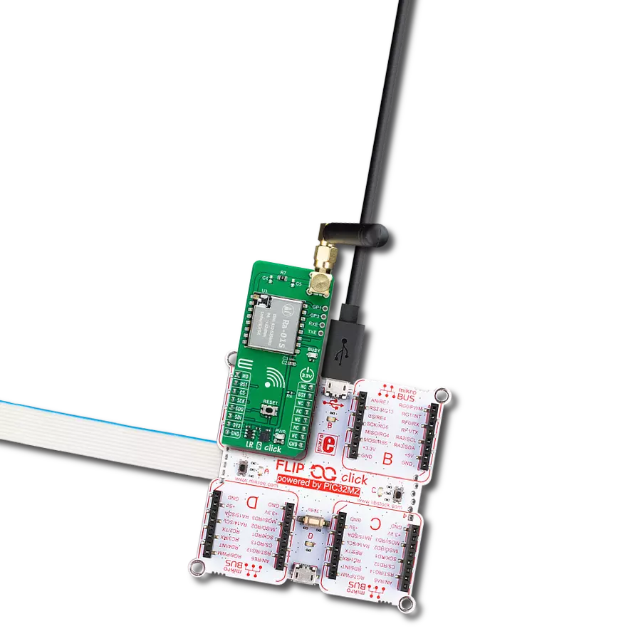
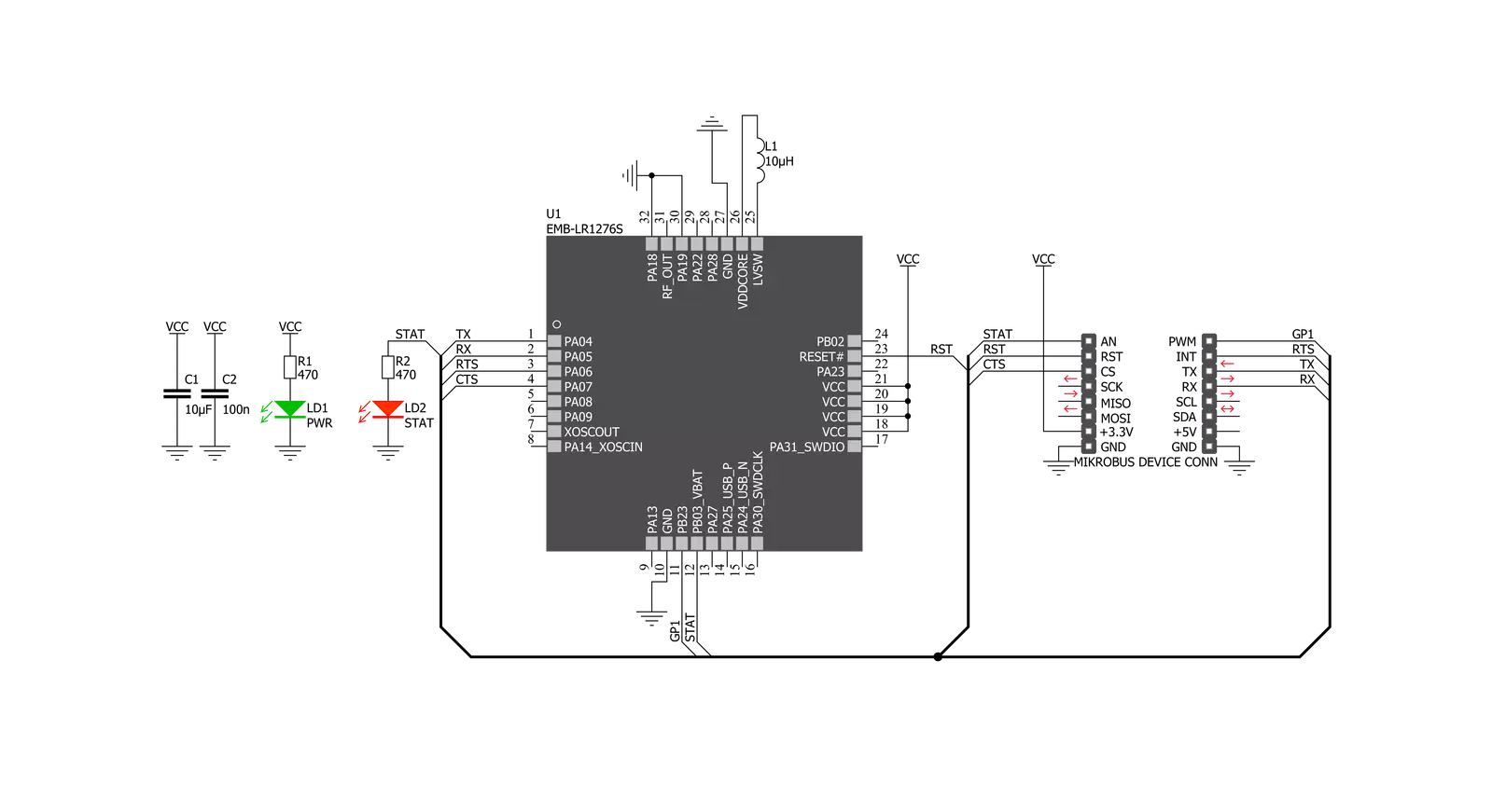
Nano LR Click is based on the EMB-LR1276S, a sub-1GHz wireless module that supports the LoRaWAN long-range wireless protocol based on the SAMR34 SiP from Embit. It offers a long-range spread spectrum communication with high interference immunity. Nano LR Click is ideal for various applications, such as IoT, home and building automation, wireless alarm and security systems, automated meter readings, industrial monitoring and control, and more. The EMB-LR1276S can be configured as an embedded microsystem or a simple data modem for
low-power applications in the 868MHz and 915MHz radio bands. It is equipped with up to 256 KB of Flash and up to 40 KB of SRAM, and it supports long-range and FSK modulation. Nano LR Click communicates with MCU using the UART interface with commonly used UART RX and TX pins with the hardware flow control pins UART CTS, RTS, RI (Clear to Send, Ready to Send, and Ring Indicator). Besides these pins, Nano LR Click also has GP1 and STAT pins, which are routed to the PWM and AN pins of the mikroBUS™ socket, respectively. STAT pin is also wired to a separate
LED indicator labeled STAT to enable quick and easy module status indication. Nano LR Click features the U.FL antenna connector with an impedance of 50Ω, so it can be equipped with the appropriate antenna that MIKROE offers. This Click board™ can be operated only with a 3.3V logic voltage level. The board must perform appropriate logic voltage level conversion before using MCUs with different logic levels. Also, it comes equipped with a library containing functions and an example code that can be used as a reference for further development.

Features overview
Development board
Nucleo 32 with STM32F031K6 MCU board provides an affordable and flexible platform for experimenting with STM32 microcontrollers in 32-pin packages. Featuring Arduino™ Nano connectivity, it allows easy expansion with specialized shields, while being mbed-enabled for seamless integration with online resources. The
board includes an on-board ST-LINK/V2-1 debugger/programmer, supporting USB reenumeration with three interfaces: Virtual Com port, mass storage, and debug port. It offers a flexible power supply through either USB VBUS or an external source. Additionally, it includes three LEDs (LD1 for USB communication, LD2 for power,
and LD3 as a user LED) and a reset push button. The STM32 Nucleo-32 board is supported by various Integrated Development Environments (IDEs) such as IAR™, Keil®, and GCC-based IDEs like AC6 SW4STM32, making it a versatile tool for developers.

Microcontroller Overview
MCU Card / MCU

Architecture
ARM Cortex-M0
MCU Memory (KB)
32
Silicon Vendor
STMicroelectronics
Pin count
32
RAM (Bytes)
4096
You complete me!
Accessories
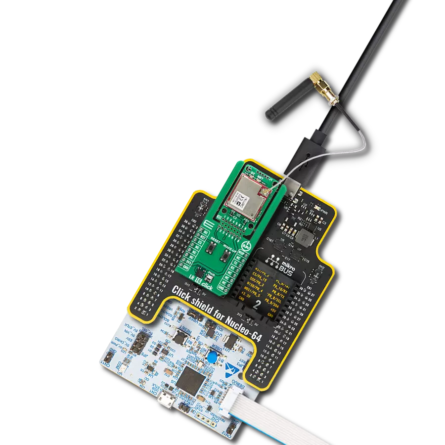
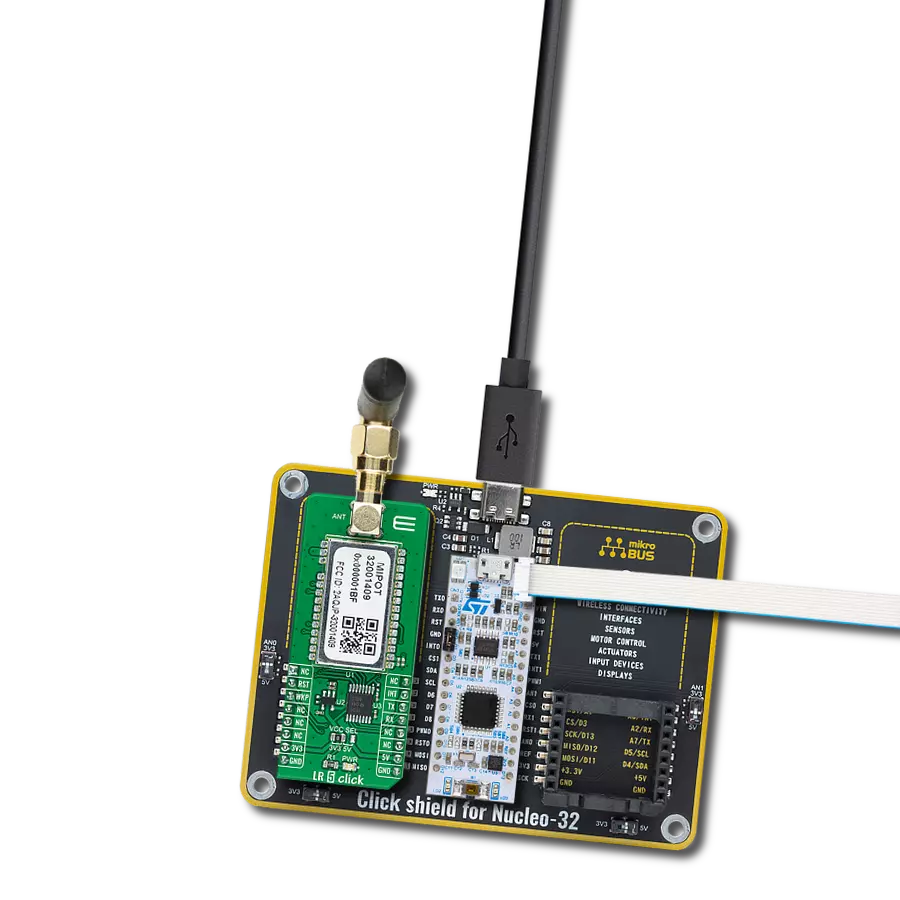
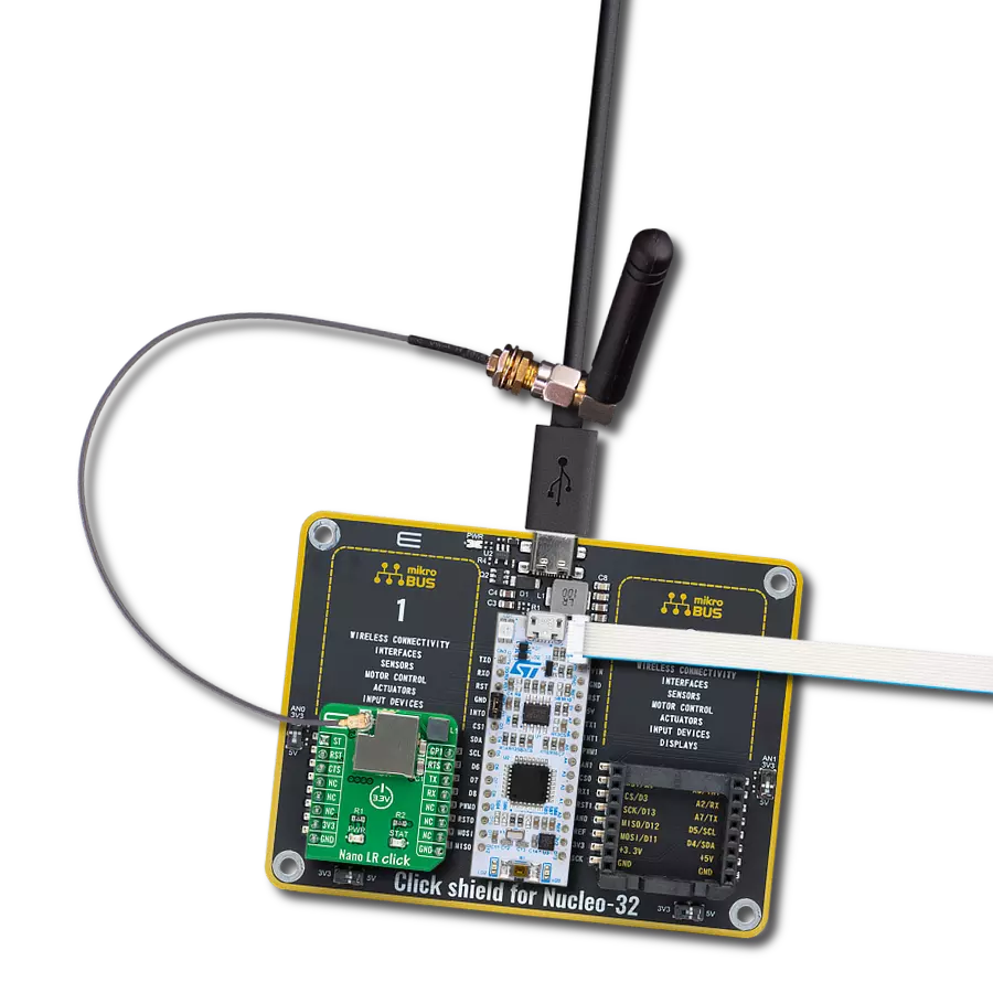
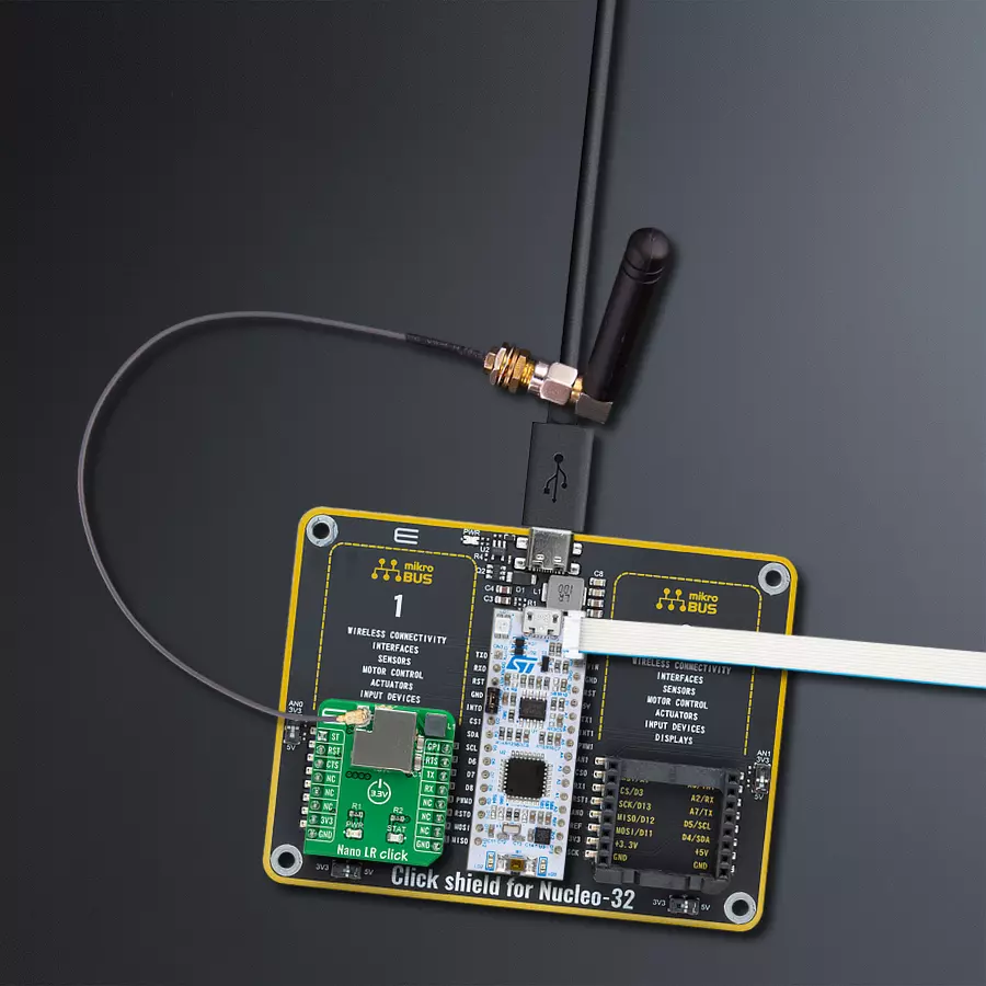
Click Shield for Nucleo-32 is the perfect way to expand your development board's functionalities with STM32 Nucleo-32 pinout. The Click Shield for Nucleo-32 provides two mikroBUS™ sockets to add any functionality from our ever-growing range of Click boards™. We are fully stocked with everything, from sensors and WiFi transceivers to motor control and audio amplifiers. The Click Shield for Nucleo-32 is compatible with the STM32 Nucleo-32 board, providing an affordable and flexible way for users to try out new ideas and quickly create prototypes with any STM32 microcontrollers, choosing from the various combinations of performance, power consumption, and features. The STM32 Nucleo-32 boards do not require any separate probe as they integrate the ST-LINK/V2-1 debugger/programmer and come with the STM32 comprehensive software HAL library and various packaged software examples. This development platform provides users with an effortless and common way to combine the STM32 Nucleo-32 footprint compatible board with their favorite Click boards™ in their upcoming projects.

Rubber Antenna GSM/GPRS Right Angle is the perfect companion for all GSM Click boards™ in our extensive lineup. This specialized antenna is designed to optimize your wireless connectivity with impressive features. With a wide frequency range spanning 824-894/1710-1990MHz or 890-960/1710-1890MHz, it can handle various frequency bands, ensuring a seamless and reliable connection. The antenna boasts an impedance of 50 Ohms and a gain of 2dB, enhancing signal reception and transmission. Its 70/180MHz bandwidth provides flexibility for diverse applications. The vertical polarization further enhances its performance. With a maximum input power capacity of 50W, this antenna ensures robust communication even under demanding conditions. Measuring a compact 50mm in length and featuring an SMA male connector, the Rubber Antenna GSM/GPRS Right Angle is a versatile and compact solution for your wireless communication needs.

IPEX-SMA cable is a type of RF (radio frequency) cable assembly. "IPEX" refers to the IPEX connector, a miniature coaxial connector commonly used in small electronic devices. "SMA" stands for SubMiniature Version A and is another coaxial connector commonly used in RF applications. An IPEX-SMA cable assembly has an IPEX connector on one end and an SMA connector on the other, allowing it to connect devices or components that use these specific connectors. These cables are often used in applications like WiFi or cellular antennas, GPS modules, and other RF communication systems where a reliable and low-loss connection is required.

Used MCU Pins
mikroBUS™ mapper
Take a closer look
Click board™ Schematic
Step by step
Project assembly

Start by selecting your development board and Click board™. Begin with the Nucleo 32 with STM32F031K6 MCU as your development board.


Software Support
Library Description
This library contains API for Nano LR Click driver.
Key functions:
nanolr_send_data- This function sends data command depends on the chosen network protocol.nanolr_uart_isr- This function reads response bytes from the device and sets flag after each received byte.nanolr_rsp_rdy- This function checks if the response is ready.
Open Source
Code example
The complete application code and a ready-to-use project are available through the NECTO Studio Package Manager for direct installation in the NECTO Studio. The application code can also be found on the MIKROE GitHub account.
/*!
 * \file
 * \brief NanoLR Click example
 *
 * # Description
 * This example reads and processes data from Nano LR Clicks.
 *
 * The demo application is composed of two sections :
 *
 * ## Application Init
 * Initializes the driver, and performs the Click default configuration.
 *
 * ## Application Task
 * Depending on the selected mode, it reads all the received data or sends a desired message
 * every 2 seconds. All data is being displayed on the USB UART.
 *
 * ## Additional Function
 * - nanolr_process ( ) - Waits until a new message is ready, then parses it and displays the message
 *                        info on the USB UART.
 *
 *
 * \author MikroE Team
 *
 */
// ------------------------------------------------------------------- INCLUDES

#include "board.h"
#include "log.h"
#include "nanolr.h"
#include "string.h"

// ------------------------------------------------------------------ VARIABLES

// #define DEMO_APP_RECEIVER
#define DEMO_APP_TRANSMITTER

#define TEXT_TO_SEND "MikroE - Nano LR Click"

static nanolr_t nanolr;
static log_t logger;

// ------------------------------------------------------- ADDITIONAL FUNCTIONS

void nanolr_process( )
{
    uint8_t tmp_buf[ 200 ];

    // Clear RX buffer
    nanolr_generic_read( &nanolr, tmp_buf, 200 );

    while ( nanolr_rsp_rdy( &nanolr ) == 0 )
    {
        nanolr_uart_isr ( &nanolr );
        Delay_ms ( 1 );
    }

    nanolr_err_t error;
    nanolr_rsp_t response;

    error = nanolr_parser_rsp( &nanolr, &response );

    if ( error == 0 )
    {
        log_printf( &logger, "** Message received!\r\n" );
        log_printf( &logger, "** Message Length: %u\r\n", response.length );
        log_printf( &logger, "** Notification ID: 0x%.2X\r\n", ( uint16_t ) response.message_id );
        log_printf( &logger, "** Options: 0x%.4X\r\n", ( response.payload[ 0 ] << 8 ) | response.payload[ 1 ] );
        log_printf( &logger, "** RSSI in dBm: %d\r\n", ( response.payload[ 2 ] << 8 ) | ~response.payload[ 3 ] );
        log_printf( &logger, "** Source Address: 0x%.4X\r\n", ( response.payload[ 4 ] << 8 ) | response.payload[ 5 ] );
        log_printf( &logger, "** Destination Address: 0x%.4X\r\n", ( response.payload[ 6 ] << 8 ) | response.payload[ 7 ] );
        log_printf( &logger, "** Message Content: " );
        for ( uint16_t cnt = 8; cnt < response.length - 4; cnt++ )
        {
            log_printf( &logger, "%c", ( uint16_t ) response.payload[ cnt ] );
        }

        log_printf( &logger, "\r\n** Checksum: 0x%.2X\r\n", ( uint16_t ) response.crc );
    }
    else
    {
        log_printf( &logger, "** Message Error!\r\n" );
    }
    log_printf( &logger, "------------------------------------\r\n" );

    log_printf( &logger, "\r\n" );
}

// ------------------------------------------------------ APPLICATION FUNCTIONS

void application_init ( void )
{
    log_cfg_t log_cfg;
    nanolr_cfg_t cfg;

    /**
     * Logger initialization.
     * Default baud rate: 115200
     * Default log level: LOG_LEVEL_DEBUG
     * @note If USB_UART_RX and USB_UART_TX
     * are defined as HAL_PIN_NC, you will
     * need to define them manually for log to work.
     * See @b LOG_MAP_USB_UART macro definition for detailed explanation.
     */
    LOG_MAP_USB_UART( log_cfg );
    log_init( &logger, &log_cfg );
    log_info( &logger, "---- Application Init ----" );

    //  Click initialization.

    nanolr_cfg_setup( &cfg );
    NANOLR_MAP_MIKROBUS( cfg, MIKROBUS_1 );
    nanolr_init( &nanolr, &cfg );

    nanolr_default_cfg( &nanolr );

    log_printf( &logger,  "----  Nano LR Click ----\r\n" );

#ifdef DEMO_APP_RECEIVER
    log_printf( &logger,  "---- RECEIVER MODE ----\r\n" );
#endif

#ifdef DEMO_APP_TRANSMITTER
    log_printf( &logger,  "---- TRANSMITER MODE ----\r\n" );
#endif
    Delay_ms ( 1000 );
    Delay_ms ( 1000 );
}

void application_task ( void )
{
#ifdef DEMO_APP_RECEIVER
    nanolr_process( );
#endif

#ifdef DEMO_APP_TRANSMITTER
    nanolr_send_data( &nanolr, TEXT_TO_SEND, strlen( TEXT_TO_SEND ) );
    log_printf( &logger, "The message \"%s\" has been sent!\r\n", ( uint8_t * ) TEXT_TO_SEND );
    log_printf( &logger, "------------------------------------------------------------\r\n" );
    Delay_ms ( 1000 );
    Delay_ms ( 1000 );
#endif
}

int main ( void )
{
    /* Do not remove this line or clock might not be set correctly. */
    #ifdef PREINIT_SUPPORTED
    preinit();
    #endif

    application_init( );

    for ( ; ; )
    {
        application_task( );
    }

    return 0;
}

// ------------------------------------------------------------------------ END
Additional Support
Resources
Category:LoRa