Establish control of any high-power application with G6D1AASIDC5 and STM32F031K6
General-purpose relays with a maximum switching voltage of 125VAC/60VDC

Published Oct 01, 2024
Click board™
RELAY Click
Dev Board
Nucleo 32 with STM32F031K6 MCU
Compiler
NECTO Studio
MCU
STM32F031K6
Easily create a remote switch that can turn things ON and OFF, like lights or motors, in your projects
A
A
Hardware Overview
How does it work?
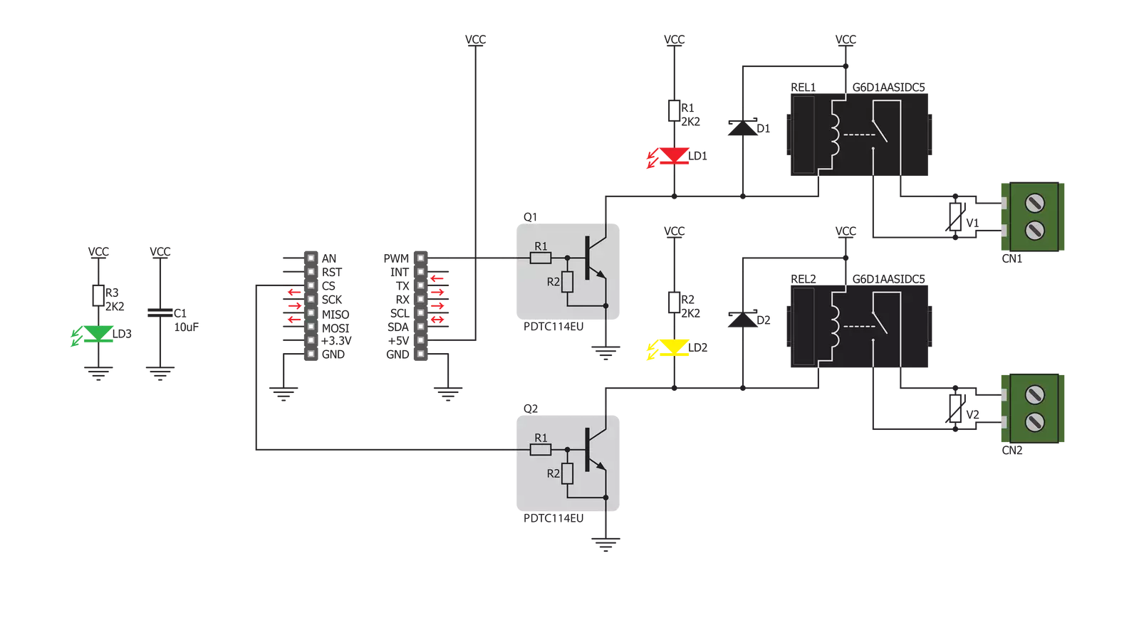
RELAY Click is based on two G6D1AASIDC5s, slim miniature relays from OMRON. Despite its size, the G6D-1A-ASI DC5 relay can withstand up to 5A and 220V AC/30V DC. It can endure up to 300,000 operations, with 30V DC and 2A. This relay has a single pole only - when the coil is energized, it will attract the internal switching elements and close the circuit, similarly to a switch. These relays are designed so relatively low currents and voltages
can easily activate their coils. For the G6D-1A-ASI DC5 relay operated at 5V, the coil current is 40mA. This makes them a perfect choice for activating them by an MCU. RELAY Click uses GPIO pins RL1 and RL2 to be controlled by the host MCU. Since RELAY Click uses an NPN RET and resistors, the host MCU is safe from the current spikes driving the relay's coils. In addition, there is an LED for every relay, each of a different color,
representing the relays' status. This Click board™ can be operated only with a 5V logic voltage level. The board must perform appropriate logic voltage level conversion before using MCUs with different logic levels. Also, it comes equipped with a library containing functions and an example code that can be used as a reference for further development.

Features overview
Development board
Nucleo 32 with STM32F031K6 MCU board provides an affordable and flexible platform for experimenting with STM32 microcontrollers in 32-pin packages. Featuring Arduino™ Nano connectivity, it allows easy expansion with specialized shields, while being mbed-enabled for seamless integration with online resources. The
board includes an on-board ST-LINK/V2-1 debugger/programmer, supporting USB reenumeration with three interfaces: Virtual Com port, mass storage, and debug port. It offers a flexible power supply through either USB VBUS or an external source. Additionally, it includes three LEDs (LD1 for USB communication, LD2 for power,
and LD3 as a user LED) and a reset push button. The STM32 Nucleo-32 board is supported by various Integrated Development Environments (IDEs) such as IAR™, Keil®, and GCC-based IDEs like AC6 SW4STM32, making it a versatile tool for developers.

Microcontroller Overview
MCU Card / MCU

Architecture
ARM Cortex-M0
MCU Memory (KB)
32
Silicon Vendor
STMicroelectronics
Pin count
32
RAM (Bytes)
4096
You complete me!
Accessories
Click Shield for Nucleo-32 is the perfect way to expand your development board's functionalities with STM32 Nucleo-32 pinout. The Click Shield for Nucleo-32 provides two mikroBUS™ sockets to add any functionality from our ever-growing range of Click boards™. We are fully stocked with everything, from sensors and WiFi transceivers to motor control and audio amplifiers. The Click Shield for Nucleo-32 is compatible with the STM32 Nucleo-32 board, providing an affordable and flexible way for users to try out new ideas and quickly create prototypes with any STM32 microcontrollers, choosing from the various combinations of performance, power consumption, and features. The STM32 Nucleo-32 boards do not require any separate probe as they integrate the ST-LINK/V2-1 debugger/programmer and come with the STM32 comprehensive software HAL library and various packaged software examples. This development platform provides users with an effortless and common way to combine the STM32 Nucleo-32 footprint compatible board with their favorite Click boards™ in their upcoming projects.

Used MCU Pins
mikroBUS™ mapper
Take a closer look
Schematic
Step by step
Project assembly

Start by selecting your development board and Click board™. Begin with the Nucleo 32 with STM32F031K6 MCU as your development board.


Track your results in real time
Application Output via Debug Mode
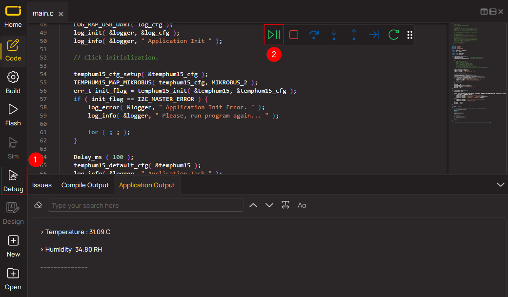
1. Once the code example is loaded, pressing the "DEBUG" button initiates the build process, programs it on the created setup, and enters Debug mode.
2. After the programming is completed, a header with buttons for various actions within the IDE becomes visible. Clicking the green "PLAY" button starts reading the results achieved with the Click board™. The achieved results are displayed in the Application Output tab.
Software Support
Library Description
This library contains API for RELAY Click driver.
Key functions:
relay_set_state- Relay set state
Open Source
Code example
This example can be found in NECTO Studio. Feel free to download the code, or you can copy the code below.
/*!
 * \file
 * \brief Relay Click example
 *
 * # Description
 * Demo application is used to shows basic controls Relay click
 *
 * The demo application is composed of two sections :
 *
 * ## Application Init
 * Configuring clicks and log objects.
 * Settings the click in the default configuration.
 *
 * ## Application Task
 * Alternately sets relays to ON-OFF state...
 *
 * \author Katarina Perendic
 *
 */
// ------------------------------------------------------------------- INCLUDES

#include "board.h"
#include "log.h"
#include "relay.h"

// ------------------------------------------------------------------ VARIABLES

static relay_t relay;
static log_t logger;

// ------------------------------------------------------ APPLICATION FUNCTIONS

void application_init ( void )
{
    log_cfg_t log_cfg;
    relay_cfg_t cfg;

    /**
     * Logger initialization.
     * Default baud rate: 115200
     * Default log level: LOG_LEVEL_DEBUG
     * @note If USB_UART_RX and USB_UART_TX
     * are defined as HAL_PIN_NC, you will
     * need to define them manually for log to work.
     * See @b LOG_MAP_USB_UART macro definition for detailed explanation.
     */
    LOG_MAP_USB_UART( log_cfg );
    log_init( &logger, &log_cfg );
    log_info(&logger, "---- Application Init ----");

    //  Click initialization.

    relay_cfg_setup( &cfg );
    RELAY_MAP_MIKROBUS( cfg, MIKROBUS_1 );
    relay_init( &relay, &cfg );

    relay_default_cfg ( &relay );
    Delay_ms( 1500 );
}

void application_task ( void )
{
    uint8_t cnt;

    //  Task implementation.

    for ( cnt = 1; cnt <= 2; cnt++)
    {
        log_info( &logger, "*** Relay %d state is ON \r\n", (uint16_t)cnt);
        relay_set_state( &relay, cnt, RELAY_STATE_ON );
        Delay_ms ( 1000 );
        log_info( &logger, "*** Relay %d state is OFF \r\n", (uint16_t)cnt);
        relay_set_state( &relay, cnt, RELAY_STATE_OFF );
        Delay_ms ( 200 );
    }
}

void main ( void )
{
    application_init( );

    for ( ; ; )
    {
        application_task( );
    }
}


// ------------------------------------------------------------------------ END


