Create interactive controls, visual effects, and precise position displays with WS2812B-2020, EC12D1564402, and STM32F031K6
Signal accurate position readings through a user-friendly rotary knob interface

Published Oct 01, 2024
Click board™
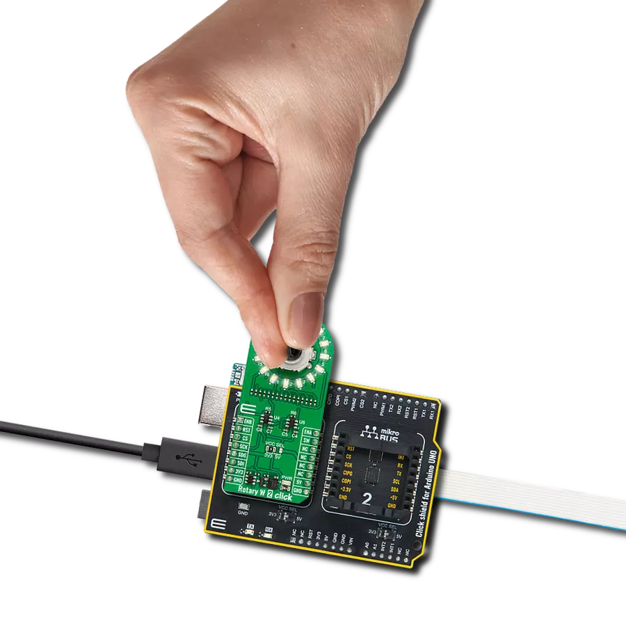
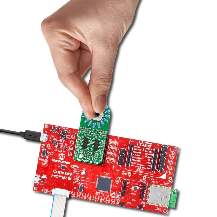
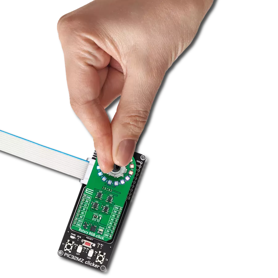
Rotary RGB Click
Dev. board
Nucleo 32 with STM32F031K6 MCU
Compiler
NECTO Studio
MCU
STM32F031K6
Ideal for applications where both tactile and visual feedback are important, showing the position or level that the encoder is set to, like volume control, position sensing, and user interface controls
A
A
Hardware Overview
How does it work?
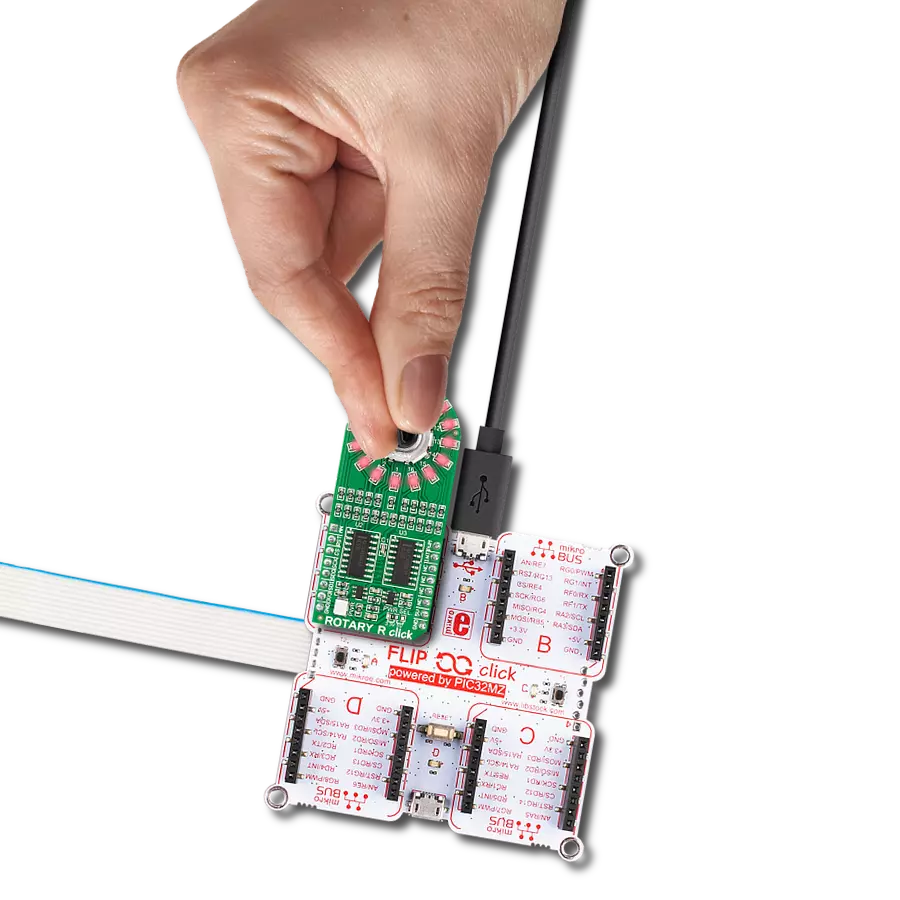
Rotary RGB Click is based on the LED ring composed of 16 individual RGB LEDs, the WS2812B-2020 from Worldsemi, alongside a high-quality rotary encoder from ALPS, the EC12D1564402, visually representing the encoder position and more. The WS2812B-2020s internal configuration includes an intelligent digital port data latch and signals to reshape the amplification drive circuit. It also consists of a precision internal oscillator and a voltage-programmable constant current control part, ensuring consistent pixel point light color height. The WS2812B-2020 is an LED with low driving voltage (5V from mikroBUS™ power rail is used as its main power supply), environmental protection and energy saving, high brightness, large scattering angle, good consistency, low power, long life, and other advantages. This Click board™ makes the perfect solution for the development of various interesting visual effects for any application, such as flexible
position, value indicator, and more. The data transfer protocol uses a single NZR communication mode via DO and DI pins of the mikroBUS™ socket. After the pixel Power-On reset sequence, the DI port of the WS2812B-2020 receives data from the host controller; the first pixel collects initial 24-bit data and then sent to the internal data latch, and the other data, which is reshaped by the internal signal reshaping amplification circuit is sent to the next cascade pixel through the DO port. After transmission for each pixel, the signal is reduced to 24bit. Pixel adopts auto reshaping transmit technology, making the pixel cascade number not limited to the signal transmission, only depending on the speed of signal transmission. The EC12D1564402 is a 15-pulse incremental rotary encoder with a push button. This encoder has unique mechanical specifications (debouncing time for its internal switches goes down to 2ms), and it can withstand a huge number of switching cycles,
up to 30.000. The supporting debouncing circuitry allows contacts to settle before the output is triggered fully. Rotating the encoder, it outputs A and B signals (out of phase to each other) on the two mikroBUS™ lines, ENA and ENB pins of the mikroBUS™ socket, alongside the push-button contact, which outputs through the SW pin of the mikroBUS™ socket. Four SN74LVC1T45 single-bit bus transceivers from Texas Instruments are used for logic-level translation of encoder and data transfer protocol signals. This Click board™ can operate with either 3.3V or 5V logic voltage levels selected via the VCC SEL jumper. This way, both 3.3V and 5V capable MCUs can use the communication lines properly. Also, this Click board™ comes equipped with a library containing easy-to-use functions and an example code that can be used as a reference for further development.

Features overview
Development board
Nucleo 32 with STM32F031K6 MCU board provides an affordable and flexible platform for experimenting with STM32 microcontrollers in 32-pin packages. Featuring Arduino™ Nano connectivity, it allows easy expansion with specialized shields, while being mbed-enabled for seamless integration with online resources. The
board includes an on-board ST-LINK/V2-1 debugger/programmer, supporting USB reenumeration with three interfaces: Virtual Com port, mass storage, and debug port. It offers a flexible power supply through either USB VBUS or an external source. Additionally, it includes three LEDs (LD1 for USB communication, LD2 for power,
and LD3 as a user LED) and a reset push button. The STM32 Nucleo-32 board is supported by various Integrated Development Environments (IDEs) such as IAR™, Keil®, and GCC-based IDEs like AC6 SW4STM32, making it a versatile tool for developers.

Microcontroller Overview
MCU Card / MCU

Architecture
ARM Cortex-M0
MCU Memory (KB)
32
Silicon Vendor
STMicroelectronics
Pin count
32
RAM (Bytes)
4096
You complete me!
Accessories
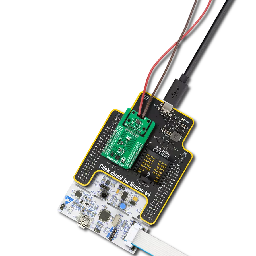
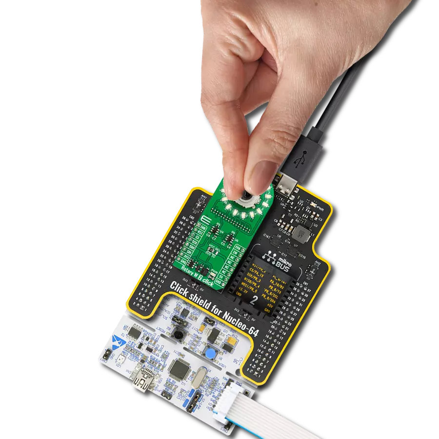
Click Shield for Nucleo-32 is the perfect way to expand your development board's functionalities with STM32 Nucleo-32 pinout. The Click Shield for Nucleo-32 provides two mikroBUS™ sockets to add any functionality from our ever-growing range of Click boards™. We are fully stocked with everything, from sensors and WiFi transceivers to motor control and audio amplifiers. The Click Shield for Nucleo-32 is compatible with the STM32 Nucleo-32 board, providing an affordable and flexible way for users to try out new ideas and quickly create prototypes with any STM32 microcontrollers, choosing from the various combinations of performance, power consumption, and features. The STM32 Nucleo-32 boards do not require any separate probe as they integrate the ST-LINK/V2-1 debugger/programmer and come with the STM32 comprehensive software HAL library and various packaged software examples. This development platform provides users with an effortless and common way to combine the STM32 Nucleo-32 footprint compatible board with their favorite Click boards™ in their upcoming projects.

Used MCU Pins
mikroBUS™ mapper
Take a closer look
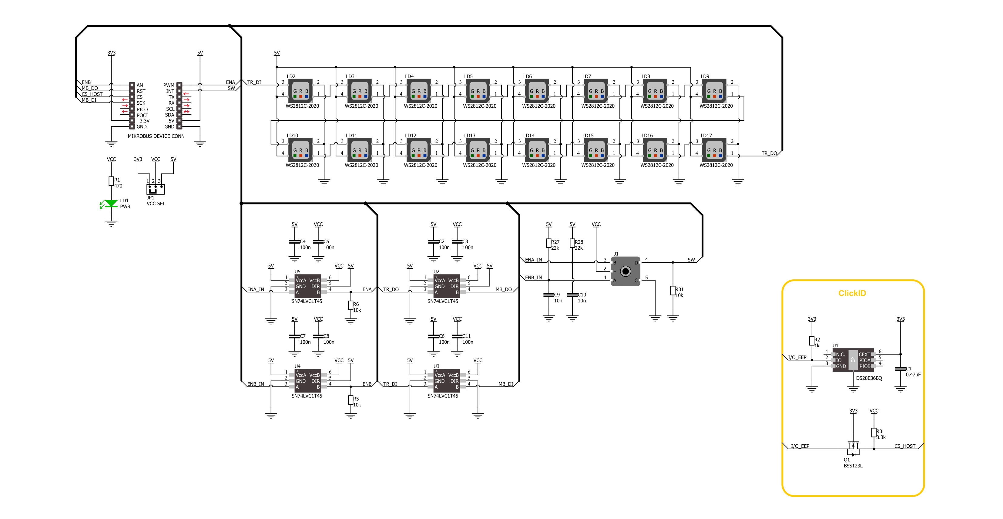
Click board™ Schematic
Step by step
Project assembly

Start by selecting your development board and Click board™. Begin with the Nucleo 32 with STM32F031K6 MCU as your development board.


Software Support
Library Description
This library contains API for Rotary RGB Click driver.
Key functions:
rotaryrgb_set_led_pos_color- This function sets the desired color for the selected LED position.rotaryrgb_set_all_leds_data- This function, using the GPIO protocol, writes the desired array of 16 elements of data to control all LEDs.rotaryrgb_get_state_switch- This function return rotary encoder switch signal, states of the SW(INT) pin.
Open Source
Code example
The complete application code and a ready-to-use project are available through the NECTO Studio Package Manager for direct installation in the NECTO Studio. The application code can also be found on the MIKROE GitHub account.
/*!
 * @file main.c
 * @brief Rotary RGB Click Example.
 *
 * # Description
 * This library contains the API for the Rotary RGB Click driver
 * to control LEDs states and a rotary encoder position readings.
 *
 * The demo application is composed of two sections :
 *
 * ## Application Init
 * Initialization of GPIO module and log UART.
 * After the driver init, the app turn off all LEDs.
 *
 * ## Application Task
 * This example demonstrates the use of the Rotary RGB Click board.
 * The demo example shows the functionality of a rotary encoder used to control RGB LEDs.
 * The switch controls the application of the colors,
 * and the encoder mechanism controls the state of the LEDs.
 *
 * ## Additional Function
 * - static void rotaryrgb_logic_zero ( void )
 * - static void rotaryrgb_logic_one ( void )
 * - static void rotaryrgb_switch_detection ( void )
 * - static void rotaryrgb_encoder_mechanism ( void )
 *
 * @note
 * Make sure the logic delays are defined for your system in the rotaryrgb_delays.h file.
 *
 * @author Nenad Filipovic
 *
 */

#include "board.h"
#include "log.h"
#include "rotaryrgb.h"
#include "rotaryrgb_delays.h"

static rotaryrgb_t rotaryrgb;   /**< Rotary RGB Click driver object. */
static log_t logger;            /**< Logger object. */

static uint8_t start_rot_status = 0;
static uint8_t led_color_sel = 0;
static uint8_t old_state = 0;
static uint8_t new_state = 1;
static uint8_t old_rot_state = 0;
static uint8_t new_rot_state = 1;
static uint16_t led_pos = 1;
static uint32_t demo_color_table[ 8 ] =
{
    ROTARYRGB_COLOR_WHITE_50,
    ROTARYRGB_COLOR_RED_50,
    ROTARYRGB_COLOR_GREEN_50,
    ROTARYRGB_COLOR_BLUE_50,
    ROTARYRGB_COLOR_LIGHT_BLUE_50,
    ROTARYRGB_COLOR_YELLOW_50,
    ROTARYRGB_COLOR_PURPLE_50,
    ROTARYRGB_COLOR_OFF
};

/**
 * @brief Rotary RGB logic zero function.
 * @details This function generates a logic zero sequence char
 * to control the LED light source.
 * @return Nothing.
 */
static void rotaryrgb_logic_zero ( void );

/**
 * @brief Rotary RGB logic one function.
 * @details This function generates a logic one sequence char
 * to control the LED light source.
 * @return Nothing.
 */
static void rotaryrgb_logic_one ( void );

/**
 * @brief Rotary RGB switch detection function.
 * @details This function is used for the switch state detection.
 * @return Nothing.
 */
static void rotaryrgb_switch_detection ( void );

/**
 * @brief Rotary RGB encoder mechanism function.
 * @details This function is used to control the state of the LEDs
 * by detecting the rotation direction of the rotary encoder.
 * @return Nothing.
 */
static void rotaryrgb_encoder_mechanism ( void );

void application_init ( void )
{
    log_cfg_t log_cfg;  /**< Logger config object. */
    rotaryrgb_cfg_t rotaryrgb_cfg;  /**< Click config object. */

    /**
     * Logger initialization.
     * Default baud rate: 115200
     * Default log level: LOG_LEVEL_DEBUG
     * @note If USB_UART_RX and USB_UART_TX
     * are defined as HAL_PIN_NC, you will
     * need to define them manually for log to work.
     * See @b LOG_MAP_USB_UART macro definition for detailed explanation.
     */
    LOG_MAP_USB_UART( log_cfg );
    log_init( &logger, &log_cfg );
    log_info( &logger, " Application Init " );

    // Click initialization.
    rotaryrgb_cfg_setup( &rotaryrgb_cfg, &rotaryrgb_logic_zero, &rotaryrgb_logic_one );
    ROTARYRGB_MAP_MIKROBUS( rotaryrgb_cfg, MIKROBUS_1 );
    if ( DIGITAL_OUT_UNSUPPORTED_PIN == rotaryrgb_init( &rotaryrgb, &rotaryrgb_cfg ) )
    {
        log_error( &logger, " Communication init." );
        for ( ; ; );
    }

    rotaryrgb_set_all_led_color( &rotaryrgb, ROTARYRGB_COLOR_OFF );
    Delay_ms ( 100 );

    log_info( &logger, " Application Task " );
    Delay_ms ( 100 );
}

void application_task ( void )
{
    rotaryrgb_set_led_pos_color( &rotaryrgb, led_pos % 17, demo_color_table[ led_color_sel ] );
    rotaryrgb_switch_detection( );
    rotaryrgb_encoder_mechanism( );
}

int main ( void )
{
    /* Do not remove this line or clock might not be set correctly. */
    #ifdef PREINIT_SUPPORTED
    preinit();
    #endif

    application_init( );

    for ( ; ; )
    {
        application_task( );
    }

    return 0;
}

static void rotaryrgb_logic_zero ( void )
{
    hal_ll_gpio_set_pin_output( &rotaryrgb.di_pin.pin );
    DELAY_TOH;
    hal_ll_gpio_clear_pin_output( &rotaryrgb.di_pin.pin );
    DELAY_TOL;
}

static void rotaryrgb_logic_one ( void )
{
    hal_ll_gpio_set_pin_output( &rotaryrgb.di_pin.pin );
    DELAY_T1H;
    hal_ll_gpio_clear_pin_output( &rotaryrgb.di_pin.pin );
    DELAY_T1L;
}

static void rotaryrgb_switch_detection ( void )
{
    if ( rotaryrgb_get_state_switch( &rotaryrgb ) )
    {
        new_state = 1;
        if ( ( 1 == new_state ) && ( 0 == old_state ) )
        {
            old_state = 1;
            led_color_sel++;
            if ( 7 < led_color_sel )
            {
                led_color_sel = 0;
            }
        }
    }
    else
    {
        old_state = 0;
    }
}

static void rotaryrgb_encoder_mechanism ( void )
{
    if ( rotaryrgb_get_state_enb( &rotaryrgb ) == rotaryrgb_get_state_ena( &rotaryrgb ) )
    {
        old_rot_state = 0;
        start_rot_status = rotaryrgb_get_state_enb( &rotaryrgb ) && rotaryrgb_get_state_ena( &rotaryrgb );
    }
    else
    {
        new_rot_state = 1;
        if ( new_rot_state != old_rot_state )
        {
            old_rot_state = 1;
            if ( start_rot_status != rotaryrgb_get_state_enb( &rotaryrgb ) )
            {
                led_pos++;
            }
            else
            {
                led_pos--;
            }

            if ( 0 == led_pos % 17 )
            {
                Delay_ms ( 1 );
                rotaryrgb_set_all_led_color( &rotaryrgb, ROTARYRGB_COLOR_OFF );
            }
        }
    }
}

// ------------------------------------------------------------------------ END
Additional Support
Resources
Category:Rotary encoder