Seamlessly integrate diverse communication protocols with XR34350 and STM32F031K6
Transforming UART signals into the language of RS-232, RS-422, and RS-485

Published Oct 01, 2024
Click board™
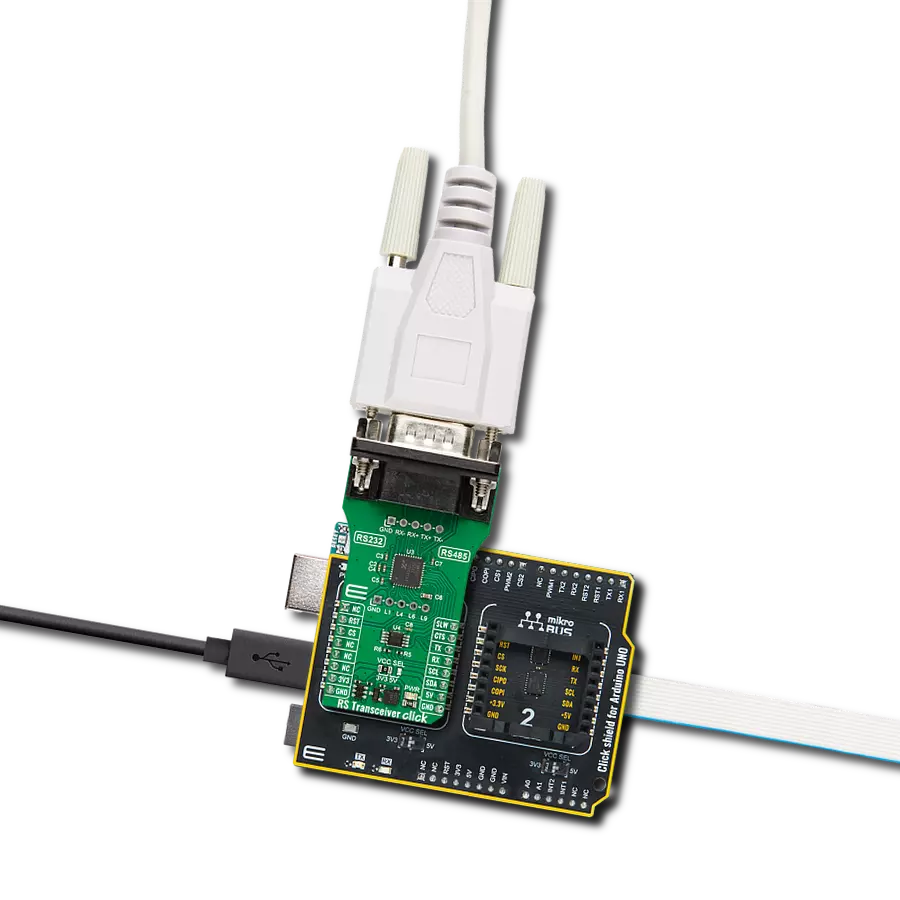
RS Transceiver Click
Dev. board
Nucleo 32 with STM32F031K6 MCU
Compiler
NECTO Studio
MCU
STM32F031K6
In a world of communication standards, our UART solution acts as a universal translator, enabling smooth dialogue between UART and RS-232, RS-422, and RS-485 interfaces
A
A
Hardware Overview
How does it work?
RS Transceiver Click is based on the XR34350, an RS-232/RS-422/RS-485 serial transceiver with internal termination and wide output swing from MaxLinear. It is an advanced multiprotocol transceiver with dual protocol serial ports, RS-232 or RS-485/RS-422. The RS-485/RS-422 modes feature one driver and one receiver (1TX/1RX) in both half and full duplex configurations, where high-speed drivers operate up to 20Mbps. The RS-485 and RS-422 are both 2-Wire protocols, where the RS-485 can have multiple commanding devices and listeners. On the other hand, the RS-422 can have only one commander and multiple listeners. The RS-232 mode features three drivers and five receivers (3TX/5RX) and provides full support for all eight signals. In the RS-232 mode, it can achieve data rates up to 1Mbps. All transceiver drivers can be slew limited to 250Kbps in any mode, thus minimizing electromagnetic interference. The XR34350 eliminates the need to design a termination resistor when sharing a single connector or a pair of lines across
multiple serial protocols. It integrates the terminal resistor and switching control, thus allowing it to be switched in and out of the circuit with a single pin. The RS-485/RS-422 receiver inputs are high impedance, while the RS-232 receiver input is pulled down, allowing up to 256 devices on a single communication bus. The RS Transceiver uses a standard UART interface to communicate with the host MCU, with commonly used UART RX and TX. In addition, the UART flow control pins CTS and RTS are available on the mikroBUS™ socket. The transceiver can be reset over the RST pin, and limiting can be activated over the SLW pin. As the mikroBUS™ socket is pin-limited, the RS Transceiver includes the TCA9536, a remote 4-bit IO expander with configuration registers from Texas Instruments, bringing an additional four I/Os to the host MCU. The TCA9536 communicates with the host MCU over the standard I2C serial interface, supporting fast mode up to 1MHz. Using this I/O expander, you can set half-duplex or full-duplex mode over the DIR1 pin of the transceiver.
There are two mode pins, MODE0 and MODE1, that you can use to select one mode between Loopback Mode, Half-Duplex RS-485 Mode #1, RS-232 Mode, and Full-Duplex RS-485/422 Mode #1. The Term pin only applies in the half-duplex and full-duplex RS-485/RS-422 modes as it enables the internal termination resistor. There are two additional headers on this Click board™. The lower one brings GND, L1, L4, L6, and L9 pins from the transceiver, and the RS-485 signals are also available on the upper header for testing purposes of the full and half duplex modes. These signals are also available on the DE-9 connector. This Click board™ can operate with either 3.3V or 5V logic voltage levels selected via the VCC SEL jumper. This way, both 3.3V and 5V capable MCUs can use the communication lines properly. Also, this Click board™ comes equipped with a library containing easy-to-use functions and an example code that can be used as a reference for further development.

Features overview
Development board
Nucleo 32 with STM32F031K6 MCU board provides an affordable and flexible platform for experimenting with STM32 microcontrollers in 32-pin packages. Featuring Arduino™ Nano connectivity, it allows easy expansion with specialized shields, while being mbed-enabled for seamless integration with online resources. The
board includes an on-board ST-LINK/V2-1 debugger/programmer, supporting USB reenumeration with three interfaces: Virtual Com port, mass storage, and debug port. It offers a flexible power supply through either USB VBUS or an external source. Additionally, it includes three LEDs (LD1 for USB communication, LD2 for power,
and LD3 as a user LED) and a reset push button. The STM32 Nucleo-32 board is supported by various Integrated Development Environments (IDEs) such as IAR™, Keil®, and GCC-based IDEs like AC6 SW4STM32, making it a versatile tool for developers.

Microcontroller Overview
MCU Card / MCU

Architecture
ARM Cortex-M0
MCU Memory (KB)
32
Silicon Vendor
STMicroelectronics
Pin count
32
RAM (Bytes)
4096
You complete me!
Accessories
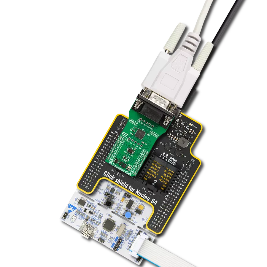
Click Shield for Nucleo-32 is the perfect way to expand your development board's functionalities with STM32 Nucleo-32 pinout. The Click Shield for Nucleo-32 provides two mikroBUS™ sockets to add any functionality from our ever-growing range of Click boards™. We are fully stocked with everything, from sensors and WiFi transceivers to motor control and audio amplifiers. The Click Shield for Nucleo-32 is compatible with the STM32 Nucleo-32 board, providing an affordable and flexible way for users to try out new ideas and quickly create prototypes with any STM32 microcontrollers, choosing from the various combinations of performance, power consumption, and features. The STM32 Nucleo-32 boards do not require any separate probe as they integrate the ST-LINK/V2-1 debugger/programmer and come with the STM32 comprehensive software HAL library and various packaged software examples. This development platform provides users with an effortless and common way to combine the STM32 Nucleo-32 footprint compatible board with their favorite Click boards™ in their upcoming projects.

DB9 Cable Female-to-Female (2m) cable is essential for establishing dependable serial data connections between devices. With its DB9 female connectors on both ends, this cable enables a seamless link between various equipment, such as computers, routers, switches, and other serial devices. Measuring 2 meters in length, it offers flexibility in arranging your setup without compromising data transmission quality. Crafted with precision, this cable ensures consistent and reliable data exchange, making it suitable for industrial applications, office environments, and home setups. Whether configuring networking equipment, accessing console ports, or utilizing serial peripherals, this cable's durable construction and robust connectors guarantee a stable connection. Simplify your data communication needs with the 2m DB9 female-to-female cable, an efficient solution designed to meet your serial connectivity requirements easily and efficiently.

Used MCU Pins
mikroBUS™ mapper
Take a closer look
Click board™ Schematic

Step by step
Project assembly

Start by selecting your development board and Click board™. Begin with the Nucleo 32 with STM32F031K6 MCU as your development board.


Track your results in real time
Application Output
1. Application Output - In Debug mode, the 'Application Output' window enables real-time data monitoring, offering direct insight into execution results. Ensure proper data display by configuring the environment correctly using the provided tutorial.

2. UART Terminal - Use the UART Terminal to monitor data transmission via a USB to UART converter, allowing direct communication between the Click board™ and your development system. Configure the baud rate and other serial settings according to your project's requirements to ensure proper functionality. For step-by-step setup instructions, refer to the provided tutorial.

3. Plot Output - The Plot feature offers a powerful way to visualize real-time sensor data, enabling trend analysis, debugging, and comparison of multiple data points. To set it up correctly, follow the provided tutorial, which includes a step-by-step example of using the Plot feature to display Click board™ readings. To use the Plot feature in your code, use the function: plot(*insert_graph_name*, variable_name);. This is a general format, and it is up to the user to replace 'insert_graph_name' with the actual graph name and 'variable_name' with the parameter to be displayed.

Software Support
Library Description
This library contains API for RS Transceiver Click driver.
Key functions:
rstransceiver_set_op_mode- RS Transceiver sets the operating mode function.rstransceiver_mode_full_duplex- RS Transceiver sets the Full-Duplex mode function.rstransceiver_device_enable- RS Transceiver enables the device function.
Open Source
Code example
The complete application code and a ready-to-use project are available through the NECTO Studio Package Manager for direct installation in the NECTO Studio. The application code can also be found on the MIKROE GitHub account.
/*!
 * @file main.c
 * @brief RS Transceiver Click example
 *
 * # Description
 * This example reads and processes data from RS Transceiver Click board™.
 * The library also includes a function for selecting the desired operating mode,
 * enabling/disabling the receiver or driver and data writing or reading.
 *
 * The demo application is composed of two sections :
 *
 * ## Application Init
 * Initialization of I2C and UART module and log UART.
 * After driver initialization, default settings turn on the device.
 *
 * ## Application Task
 * This example demonstrates the use of the RS Transceiver Click board™.
 * The app shows the device configured in loopback mode,
 * sends a "MikroE" message, reads the received data and parses it.
 * Results are being sent to the UART Terminal, where you can track their changes.
 *
 * @author Nenad Filipovic
 *
 */

#include "board.h"
#include "log.h"
#include "rstransceiver.h"

#define DEMO_MESSAGE "\r\nMikroE\r\n"
#define PROCESS_BUFFER_SIZE 20

static rstransceiver_t rstransceiver;
static log_t logger;

static char app_buf[ PROCESS_BUFFER_SIZE ] = { 0 };

void application_init ( void )
{
    log_cfg_t log_cfg;  /**< Logger config object. */
    rstransceiver_cfg_t rstransceiver_cfg;  /**< Click config object. */

    /**
     * Logger initialization.
     * Default baud rate: 115200
     * Default log level: LOG_LEVEL_DEBUG
     * @note If USB_UART_RX and USB_UART_TX
     * are defined as HAL_PIN_NC, you will
     * need to define them manually for log to work.
     * See @b LOG_MAP_USB_UART macro definition for detailed explanation.
     */
    LOG_MAP_USB_UART( log_cfg );
    log_init( &logger, &log_cfg );
    log_info( &logger, " Application Init " );

    // Click initialization.
    rstransceiver_cfg_setup( &rstransceiver_cfg );
    RSTRANSCEIVER_MAP_MIKROBUS( rstransceiver_cfg, MIKROBUS_1 );
    if ( I2C_MASTER_ERROR == rstransceiver_init( &rstransceiver, &rstransceiver_cfg ) )
    {
        log_error( &logger, " Communication init." );
        for ( ; ; );
    }
    Delay_ms ( 100 );

    if ( RSTRANSCEIVER_ERROR == rstransceiver_default_cfg ( &rstransceiver ) )
    {
        log_error( &logger, " Default configuration." );
        for ( ; ; );
    }

    log_info( &logger, " Application Task " );
    Delay_ms ( 100 );
}

void application_task ( void )
{
    if ( 0 < rstransceiver_generic_write( &rstransceiver, DEMO_MESSAGE, strlen( DEMO_MESSAGE ) ) )
    {
        if ( 0 < rstransceiver_generic_read( &rstransceiver, app_buf, strlen( DEMO_MESSAGE ) ) )
        {
            log_printf( &logger, "%s", app_buf );
            memset( app_buf, 0, PROCESS_BUFFER_SIZE );
            Delay_ms ( 1000 );
            Delay_ms ( 1000 );
        }
    }
}

int main ( void )
{
    /* Do not remove this line or clock might not be set correctly. */
    #ifdef PREINIT_SUPPORTED
    preinit();
    #endif

    application_init( );

    for ( ; ; )
    {
        application_task( );
    }

    return 0;
}

// ------------------------------------------------------------------------ END