Experience wireless freedom like never before with SP1ML and STM32F031K6
Simplify connectivity, amplify possibilities!

Published Oct 01, 2024
Click board™
SPIRIT Click
Dev. board
Nucleo 32 with STM32F031K6 MCU
Compiler
NECTO Studio
MCU
STM32F031K6
Our 868MHz ultra-low-power RF module makes long-distance wireless communication effortless, ensuring robust connections for remote monitoring and control systems.
A
A
Hardware Overview
How does it work?
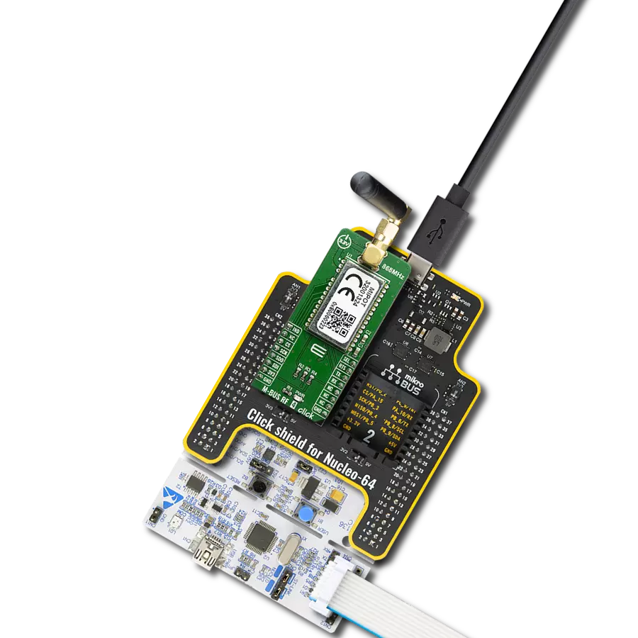
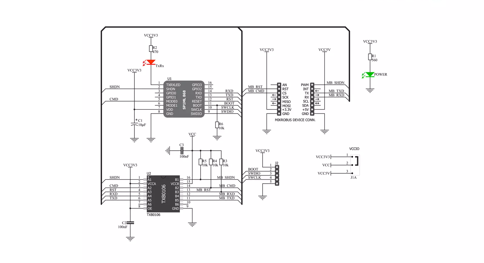
Spirit Click is based on the SP1ML, a Spirit1 868MHz low-power RF module with an integrated microcontroller from STMicroelectronics. Besides the STM32L1 MCU, the module integrates a filter/balun and a chip antenna. Over the chip antenna, it achieves output power up to +11.6dBm and uses modulation schemes 2-FSK, GFSK, GMSK, OOK, and ASK. Its compact size, integrated design, all necessary FCC modular approvals, and CE compliance reduce time-to-market, making it an ideal choice for wireless applications. The data rates depend on the used modulation. The UART host interface allows simple connection to an external microcontroller with standard firmware, allowing AT commands to facilitate RF configuration, data transmission, and reception using simple point-to-point communication. It can also switch the module between the command and operating modes. In addition, the serial wire
debug interface (SWD) is also available, as the Spirit Click and the SP1ML module support custom module firmware. The 5-pin header, aside from the module, can also be used for debugging purposes. Additional RXTX LED status indicator shows when the data is sent or received. The command mode allows module configuration and status interrogation using an extended AT-style command set. In operating mode, the module serves its primary purpose as a wireless transceiver. Following power-up or reset, the module starts in operating mode with the current configuration loaded from EEPROM. In operating mode, data received from the host on the UART interface will be wirelessly transmitted by the Spirit1 radio using the current configuration settings for frequency, data rate, modulation, and output power. Conversely, any data received by Spirit1 that meets the configured filtering criteria
will be output to the UART interface. In command mode, the module will accept commands to configure module settings and interrogate module status. Spirit Click uses a standard UART interface to communicate with the host MCU, supporting baud rates from 9600 up to 250000bps, while 38400bps is the default value. You can reset the Spirit Click over the RST pin and shut it down over the SHD pin. To change the operating mode, there is the CMD pin. This Click board™ can operate with either 3.3V or 5V logic voltage levels selected via the LOGIC SEL jumper. This way, both 3.3V and 5V capable MCUs can use the communication lines properly. Also, this Click board™ comes equipped with a library containing easy-to-use functions and an example code that can be used for further development.


Features overview
Development board
Nucleo 32 with STM32F031K6 MCU board provides an affordable and flexible platform for experimenting with STM32 microcontrollers in 32-pin packages. Featuring Arduino™ Nano connectivity, it allows easy expansion with specialized shields, while being mbed-enabled for seamless integration with online resources. The
board includes an on-board ST-LINK/V2-1 debugger/programmer, supporting USB reenumeration with three interfaces: Virtual Com port, mass storage, and debug port. It offers a flexible power supply through either USB VBUS or an external source. Additionally, it includes three LEDs (LD1 for USB communication, LD2 for power,
and LD3 as a user LED) and a reset push button. The STM32 Nucleo-32 board is supported by various Integrated Development Environments (IDEs) such as IAR™, Keil®, and GCC-based IDEs like AC6 SW4STM32, making it a versatile tool for developers.

Microcontroller Overview
MCU Card / MCU

Architecture
ARM Cortex-M0
MCU Memory (KB)
32
Silicon Vendor
STMicroelectronics
Pin count
32
RAM (Bytes)
4096
You complete me!
Accessories
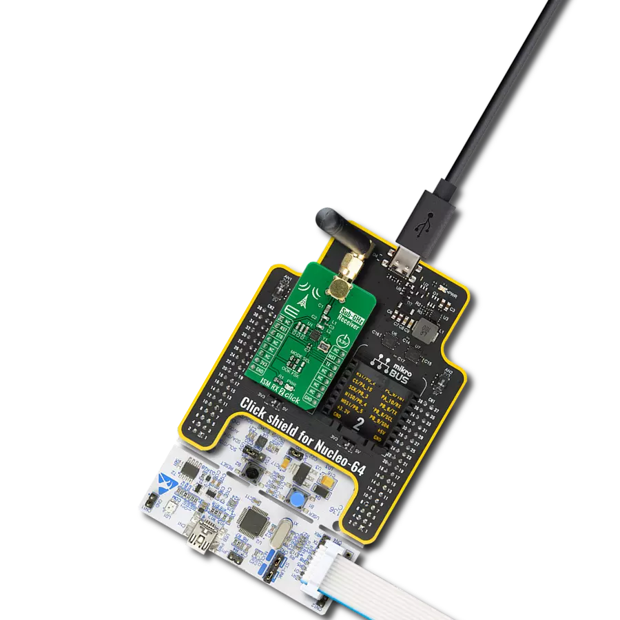
Click Shield for Nucleo-32 is the perfect way to expand your development board's functionalities with STM32 Nucleo-32 pinout. The Click Shield for Nucleo-32 provides two mikroBUS™ sockets to add any functionality from our ever-growing range of Click boards™. We are fully stocked with everything, from sensors and WiFi transceivers to motor control and audio amplifiers. The Click Shield for Nucleo-32 is compatible with the STM32 Nucleo-32 board, providing an affordable and flexible way for users to try out new ideas and quickly create prototypes with any STM32 microcontrollers, choosing from the various combinations of performance, power consumption, and features. The STM32 Nucleo-32 boards do not require any separate probe as they integrate the ST-LINK/V2-1 debugger/programmer and come with the STM32 comprehensive software HAL library and various packaged software examples. This development platform provides users with an effortless and common way to combine the STM32 Nucleo-32 footprint compatible board with their favorite Click boards™ in their upcoming projects.

Used MCU Pins
mikroBUS™ mapper
Take a closer look
Click board™ Schematic
Step by step
Project assembly

Start by selecting your development board and Click board™. Begin with the Nucleo 32 with STM32F031K6 MCU as your development board.


Track your results in real time
Application Output
1. Application Output - In Debug mode, the 'Application Output' window enables real-time data monitoring, offering direct insight into execution results. Ensure proper data display by configuring the environment correctly using the provided tutorial.

2. UART Terminal - Use the UART Terminal to monitor data transmission via a USB to UART converter, allowing direct communication between the Click board™ and your development system. Configure the baud rate and other serial settings according to your project's requirements to ensure proper functionality. For step-by-step setup instructions, refer to the provided tutorial.

3. Plot Output - The Plot feature offers a powerful way to visualize real-time sensor data, enabling trend analysis, debugging, and comparison of multiple data points. To set it up correctly, follow the provided tutorial, which includes a step-by-step example of using the Plot feature to display Click board™ readings. To use the Plot feature in your code, use the function: plot(*insert_graph_name*, variable_name);. This is a general format, and it is up to the user to replace 'insert_graph_name' with the actual graph name and 'variable_name' with the parameter to be displayed.

Software Support
Library Description
This library contains API for SPIRIT Click driver.
Key functions:
spirit_power_module- Function for power mode of SPIRIT click.spirit_reset- Function for reseting SPIRIT click.spirit_set_mode- Function for setting mode of SPIRIT click.
Open Source
Code example
The complete application code and a ready-to-use project are available through the NECTO Studio Package Manager for direct installation in the NECTO Studio. The application code can also be found on the MIKROE GitHub account.
/*!
 * @file main.c
 * @brief SPIRIT Click Example.
 *
 * # Description
 * This example reads and processes data from SPIRIT Click.
 *
 * The demo application is composed of two sections :
 *
 * ## Application Init
 * Initializes the driver and configures the Click board.
 *
 * ## Application Task
 * Depending on the selected mode, it reads all the received data or sends the desired message
 * every 2 seconds.
 *
 * ## Additional Function
 * - static err_t spirit_process ( void ) - The general process of collecting the received data.
 *
 * @author Jelena Milosavljevic
 *
 */
// ------------------------------------------------------------------- INCLUDES

#include "board.h"
#include "log.h"
#include "spirit.h"

#define PROCESS_BUFFER_SIZE 500
#define PROCESS_COUNTER     20

#define TEXT_TO_SEND           "MikroE - SPIRIT Click board\r\n"

#define DEMO_APP_RECEIVER
//#define DEMO_APP_TRANSMITTER

static spirit_t spirit;
static log_t logger;

static char app_buf[ PROCESS_BUFFER_SIZE ] = { 0 };
static int32_t app_buf_len = 0;
static int32_t app_buf_cnt = 0;

/**
 * @brief SPIRIT data reading function.
 * @details This function reads data from device and concatenates data to application buffer.
 *
 * @return @li @c  0 - Read some data.
 *         @li @c -1 - Nothing is read.
 *         @li @c -2 - Application buffer overflow.
 *
 * See #err_t definition for detailed explanation.
 * @note None.
 */
static void spirit_process ( void );

// ------------------------------------------------------ APPLICATION FUNCTIONS

void application_init ( void )
{
    log_cfg_t log_cfg;
    spirit_cfg_t cfg;

    /**
     * Logger initialization.
     * Default baud rate: 115200
     * Default log level: LOG_LEVEL_DEBUG
     * @note If USB_UART_RX and USB_UART_TX
     * are defined as HAL_PIN_NC, you will
     * need to define them manually for log to work.
     * See @b LOG_MAP_USB_UART macro definition for detailed explanation.
     */
    LOG_MAP_USB_UART( log_cfg );
    log_init( &logger, &log_cfg );
    log_info( &logger, "---- Application Init ----" );

    //  Click initialization.

    spirit_cfg_setup( &cfg );
    SPIRIT_MAP_MIKROBUS( cfg, MIKROBUS_1 );
    spirit_init( &spirit, &cfg );
    Delay_ms ( 1000 );

    log_info( &logger, "---- Configuring the module ----" );
    spirit_power_module( &spirit, SPIRIT_MODULE_WAKE_UP );
    spirit_reset( &spirit );
    spirit_set_mode( &spirit, SPIRIT_OPERATING_MODE );
    Delay_ms ( 1000 );
    log_printf( &logger, "COMMAND MODE\r\n" );
    spirit_send_cmd( &spirit, SPIRIT_CMD_ENTER_COMMAND_MODE );
    spirit_process( );
    log_printf( &logger, "FIRMWARE VERSION\r\n" );
    spirit_send_cmd( &spirit, SPIRIT_CMD_READ_MODULE_VERSION );
    spirit_process( );
    log_printf( &logger, "TXRX LED - OPEN DRAIN OUTPUT\r\n" );
    spirit_send_cmd_with_parameter( &spirit, SPIRIT_CMD_CFG_TXRX_LED, SPIRIT_PCFG_TXRXLED_OPEN_DRAIN );
    spirit_process( );
    log_printf( &logger, "STORE CONFIG\r\n" );
    spirit_send_cmd( &spirit, SPIRIT_CMD_STORE_CURRENT_CONFIG );
    spirit_process( );
    log_printf( &logger, "OPERATING MODE\r\n" );
    spirit_send_cmd( &spirit, SPIRIT_CMD_ENTER_OPERATING_MODE );
    spirit_process( );
    log_info( &logger, "---- The module has been configured ----" );
#ifdef DEMO_APP_RECEIVER
    log_info( &logger, "---- RECEIVER MODE ----" );
#endif
#ifdef DEMO_APP_TRANSMITTER
    log_info( &logger, "---- TRANSMITTER MODE ----" );
#endif
    Delay_ms ( 1000 );
}

void application_task ( void ) {
#ifdef DEMO_APP_RECEIVER
    spirit_process( );
#endif

#ifdef DEMO_APP_TRANSMITTER
    spirit_generic_write( &spirit, TEXT_TO_SEND, strlen( TEXT_TO_SEND ) );
    log_info( &logger, "---- The message has been sent ----" );
    Delay_ms ( 1000 );
    Delay_ms ( 1000 );
#endif
}

int main ( void )
{
    /* Do not remove this line or clock might not be set correctly. */
    #ifdef PREINIT_SUPPORTED
    preinit();
    #endif

    application_init( );

    for ( ; ; )
    {
        application_task( );
    }

    return 0;
}

static void spirit_process ( void ) {
    int32_t rsp_size;

    char uart_rx_buffer[ PROCESS_BUFFER_SIZE ] = { 0 };
    uint8_t process_cnt = PROCESS_COUNTER;

    while( process_cnt != 0 ) {

        rsp_size = spirit_generic_read( &spirit, &uart_rx_buffer, PROCESS_BUFFER_SIZE );

        if ( rsp_size > 0 ) {

            for ( uint8_t cnt = 0; cnt < rsp_size; cnt++ ) {

                log_printf( &logger, "%c", uart_rx_buffer[ cnt ] );
                if ( uart_rx_buffer[ cnt ] == '\n' ) {

                    log_printf( &logger, "-----------------------------\r\n" );
                }
            }
        }
        else {

            process_cnt--;

            // Process delay
            Delay_100ms( );
        }
    }
}

// ------------------------------------------------------------------------ END
Additional Support
Resources
Category:Sub-1 GHz Transceievers