Shape your audio landscape with CS3310 and STM32F031K6
A symphony of sound awaits: Unleash your inner audiophile

Published Oct 01, 2024
Click board™
Volume Click
Dev. board
Nucleo 32 with STM32F031K6 MCU
Compiler
NECTO Studio
MCU
STM32F031K6
Our stereo digital volume control device is designed to give you unparalleled control over your audio, allowing you to fine-tune your sound to perfection
A
A
Hardware Overview
How does it work?
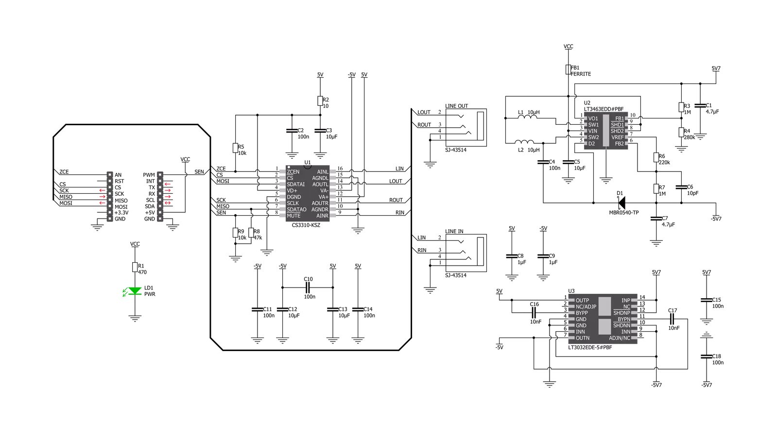
Volume Click is based on the CS3310, a complete stereo digital volume control designed specifically for audio systems from Cirrus Logic. It features a 16-bit serial interface that controls two independent, low-distortion audio channels. The left and right levels of the analog input channels are set by a 16-bit serial data word (the first 8 bits address the right while the remaining 8 bits address the left channel). The CS3310 includes an array of well-matched resistors and a low-noise active output stage capable of driving a 600Ω load. A total adjustable range of 127dB, in 0.5dB steps, is achieved through 95.5dB of attenuation and 31.5dB of gain. The digital section power supply of the Volume Click is achieved through a 5V pin from a mikroBUS™ socket while the device itself is powered by ±5V from the LT3032, a dual 150mA positive and negative low noise low dropout linear
regulator with micropower quiescent current from Analog Devices. Volume Click communicates with MCU using the standard SPI serial interface with two additional GPIO pins that accept 16-bit data and enable users to read the current volume setting. Those two GPIO pins brought with this Click board™ are used for Zero Crossing Enable and Hardware MUTE functions. Once in operation, the CS3310 can be brought to a muted state with the MUTE pin labeled as SEN routed on the PWM pin of the mikroBUS™ socket or by writing zeros to the volume control registers. A volume control change occurs after the CS pin latches the data in the volume control data register, and two zero crossings are detected. The zero-crossing enable pin, labeled as ZCE routed on the AN pin of the mikroBUS™ socket, turns on or off the zero-crossing detection function and the 18ms
time-out circuit. If two zero crossings are not detected within 18ms of the change in the CS pin, the new volume setting is implemented. Upon initial application of power, the SEN pin of the CS3310 should be set to LOW to initiate a Power-Up sequence. This sequence sets the serial shift register and the volume control register to zero and performs an offset calibration. The device should remain muted until the supply voltages have settled to ensure accurate calibration. This Click board™ can be operated only with a 5V logic voltage level. The board must perform appropriate logic voltage level conversion before using MCUs with different logic levels. Also, it comes equipped with a library containing functions and an example code that can be used as a reference for further development.


Features overview
Development board
Nucleo 32 with STM32F031K6 MCU board provides an affordable and flexible platform for experimenting with STM32 microcontrollers in 32-pin packages. Featuring Arduino™ Nano connectivity, it allows easy expansion with specialized shields, while being mbed-enabled for seamless integration with online resources. The
board includes an on-board ST-LINK/V2-1 debugger/programmer, supporting USB reenumeration with three interfaces: Virtual Com port, mass storage, and debug port. It offers a flexible power supply through either USB VBUS or an external source. Additionally, it includes three LEDs (LD1 for USB communication, LD2 for power,
and LD3 as a user LED) and a reset push button. The STM32 Nucleo-32 board is supported by various Integrated Development Environments (IDEs) such as IAR™, Keil®, and GCC-based IDEs like AC6 SW4STM32, making it a versatile tool for developers.

Microcontroller Overview
MCU Card / MCU

Architecture
ARM Cortex-M0
MCU Memory (KB)
32
Silicon Vendor
STMicroelectronics
Pin count
32
RAM (Bytes)
4096
You complete me!
Accessories
Click Shield for Nucleo-32 is the perfect way to expand your development board's functionalities with STM32 Nucleo-32 pinout. The Click Shield for Nucleo-32 provides two mikroBUS™ sockets to add any functionality from our ever-growing range of Click boards™. We are fully stocked with everything, from sensors and WiFi transceivers to motor control and audio amplifiers. The Click Shield for Nucleo-32 is compatible with the STM32 Nucleo-32 board, providing an affordable and flexible way for users to try out new ideas and quickly create prototypes with any STM32 microcontrollers, choosing from the various combinations of performance, power consumption, and features. The STM32 Nucleo-32 boards do not require any separate probe as they integrate the ST-LINK/V2-1 debugger/programmer and come with the STM32 comprehensive software HAL library and various packaged software examples. This development platform provides users with an effortless and common way to combine the STM32 Nucleo-32 footprint compatible board with their favorite Click boards™ in their upcoming projects.

Used MCU Pins
mikroBUS™ mapper
Take a closer look
Click board™ Schematic
Step by step
Project assembly

Start by selecting your development board and Click board™. Begin with the Nucleo 32 with STM32F031K6 MCU as your development board.


Track your results in real time
Application Output
1. Application Output - In Debug mode, the 'Application Output' window enables real-time data monitoring, offering direct insight into execution results. Ensure proper data display by configuring the environment correctly using the provided tutorial.

2. UART Terminal - Use the UART Terminal to monitor data transmission via a USB to UART converter, allowing direct communication between the Click board™ and your development system. Configure the baud rate and other serial settings according to your project's requirements to ensure proper functionality. For step-by-step setup instructions, refer to the provided tutorial.

3. Plot Output - The Plot feature offers a powerful way to visualize real-time sensor data, enabling trend analysis, debugging, and comparison of multiple data points. To set it up correctly, follow the provided tutorial, which includes a step-by-step example of using the Plot feature to display Click board™ readings. To use the Plot feature in your code, use the function: plot(*insert_graph_name*, variable_name);. This is a general format, and it is up to the user to replace 'insert_graph_name' with the actual graph name and 'variable_name' with the parameter to be displayed.

Software Support
Library Description
This library contains API for Volume Click driver.
Key functions:
volume_set_vol_gain- Set volume gain functionvolume_power_up- Power Up functionvolume_hw_mute- Hardware MUTE function
Open Source
Code example
The complete application code and a ready-to-use project are available through the NECTO Studio Package Manager for direct installation in the NECTO Studio. The application code can also be found on the MIKROE GitHub account.
/*!
 * @file main.c
 * @brief Volume Click example
 *
 * # Description
 * This example sets up the device and performs volume turn up and down.
 *
 * The demo application is composed of two sections :
 *
 * ## Application Init
 * Initializes drivers and powers up the device.
 *
 * ## Application Task
 * Circles the volume from -40 [dB] to 10 [dB] back and forth.
 *
 * @author Stefan Nikolic
 *
 */

#include "board.h"
#include "log.h"
#include "volume.h"

float left_speaker_gain;
float right_speaker_gain;
uint8_t one_circle;

static volume_t volume;
static log_t logger;

void application_init ( void ) {
    log_cfg_t log_cfg;  /**< Logger config object. */
    volume_cfg_t volume_cfg;  /**< Click config object. */

    /**
     * Logger initialization.
     * Default baud rate: 115200
     * Default log level: LOG_LEVEL_DEBUG
     * @note If USB_UART_RX and USB_UART_TX
     * are defined as HAL_PIN_NC, you will
     * need to define them manually for log to work.
     * See @b LOG_MAP_USB_UART macro definition for detailed explanation.
     */
    LOG_MAP_USB_UART( log_cfg );
    log_init( &logger, &log_cfg );
    log_info( &logger, " Application Init " );

    // Click initialization.

    volume_cfg_setup( &volume_cfg );
    VOLUME_MAP_MIKROBUS( volume_cfg, MIKROBUS_1 );
    err_t init_flag  = volume_init( &volume, &volume_cfg );
    if ( init_flag == SPI_MASTER_ERROR ) {
        log_error( &logger, " Application Init Error. " );
        log_info( &logger, " Please, run program again... " );

        for ( ; ; );
    }

    volume_default_cfg ( &volume );
    log_info( &logger, " Application Task " );
}

void application_task ( void ) {
    left_speaker_gain  = -40;
    right_speaker_gain = -40;
    one_circle = 0;

    log_printf( &logger, " Turning volume up.\r\n" );
    while ( one_circle < 2 ) {
        if ( one_circle == 0 ) {
            if ( left_speaker_gain <= 10 || right_speaker_gain <= 10 ) {
                volume_set_vol_gain( &volume, left_speaker_gain, right_speaker_gain );
                left_speaker_gain += 0.5;
                right_speaker_gain += 0.5;
                Delay_ms ( 50 );
            } else {
                one_circle++;
                log_printf( &logger, " Turning volume down.\r\n" );
            }
        } else if ( left_speaker_gain >= -40 || right_speaker_gain >= -40 ) {
            volume_set_vol_gain( &volume, left_speaker_gain, right_speaker_gain );
            left_speaker_gain -= 0.5;
            right_speaker_gain -= 0.5;
            Delay_ms ( 50 );
        } else one_circle++;
    }
}

int main ( void )
{
    /* Do not remove this line or clock might not be set correctly. */
    #ifdef PREINIT_SUPPORTED
    preinit();
    #endif

    application_init( );

    for ( ; ; )
    {
        application_task( );
    }

    return 0;
}

// ------------------------------------------------------------------------ END


