Unleash the waveform symphony using AD9833 and STM32G474RE
Sine/triangle/square waveform generator

Published Nov 08, 2024
Click board™
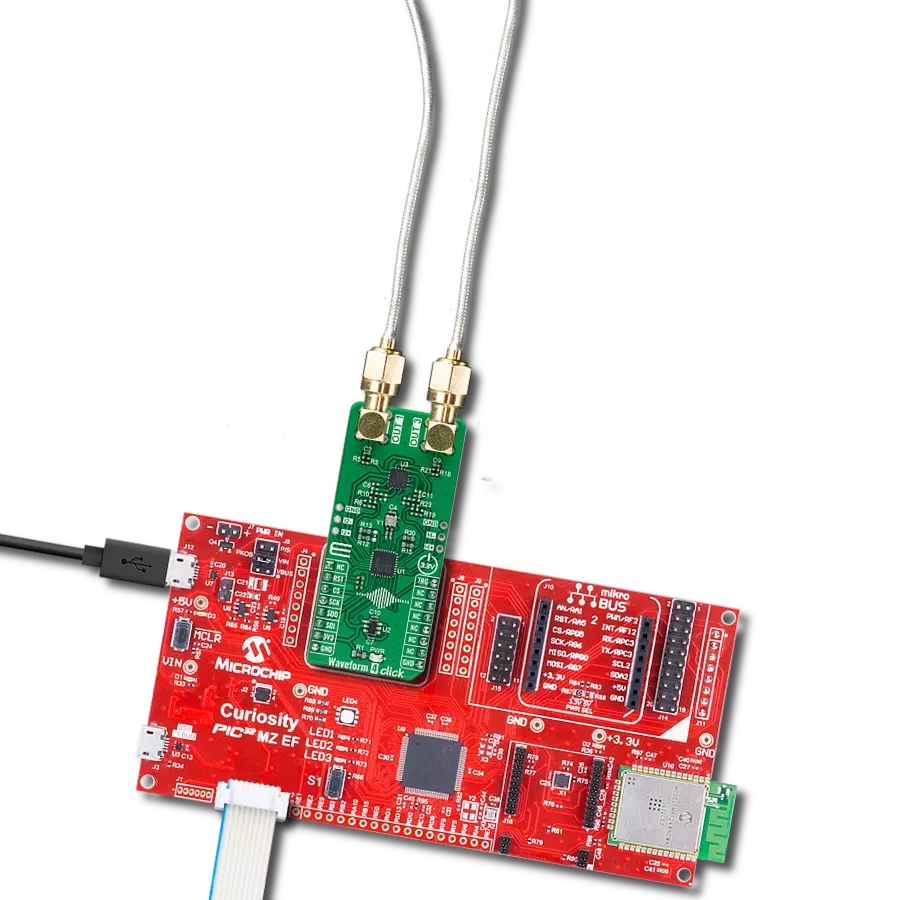
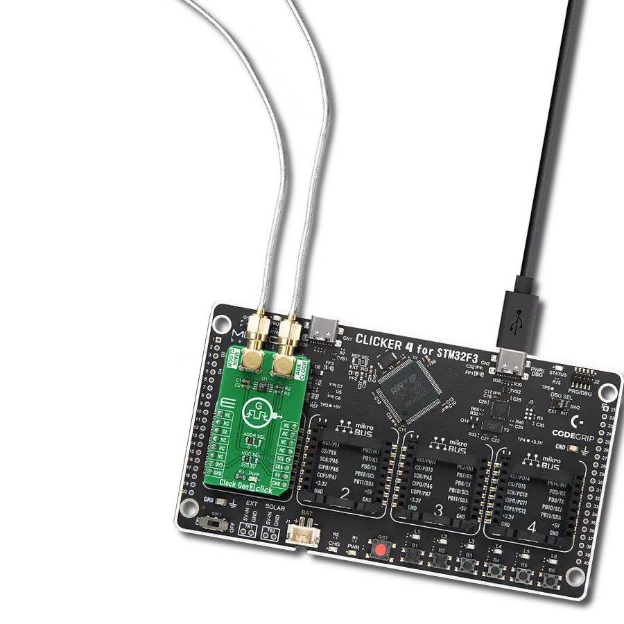
Waveform Click
Dev. board
Nucleo 64 with STM32G474RE MCU
Compiler
NECTO Studio
MCU
STM32G474RE
Explore this comprehensive waveform generator and add seamless signal generation to your solution
A
A
Hardware Overview
How does it work?
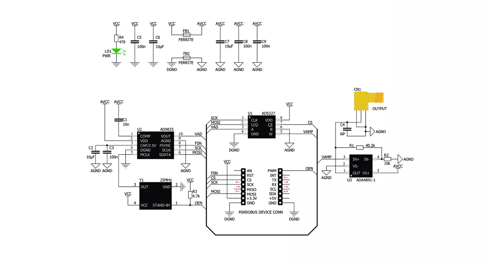
Waveform Click is based on the AD9833, a low-power, programmable waveform generator from Analog Devices. This company is well-established in the high-quality Digital Signal Processing (DSP) solutions market. The AD9833 IC is based on Direct Digital Synthesis (DDS), producing a waveform with a programmable frequency and selectable wave shape at its output. The AD9833 and the AD5227, a digital potentiometer IC from the same company, are controlled over the SPI interface, allowing both the frequency and amplitude to be changed very quickly without additional latency. DDS produces an analog waveform by exploiting the fact that the signal's phase is changed linearly. For simple periodic functions such as the sine function, the phase changes linearly between 0 and 2π. This allows building the Numerically Controlled Oscillator (NCO) block, which outputs a numerical value that linearly changes over time, between 0 and 228 – 1 (since the AD9833 IC has a 28-bit phase accumulator). The continuously changing output of the NCO block is used as the index for the Lookup Table (LUT), which contains amplitudes of the output waveform. The faster the NCO output changes, the higher the output signal frequency,
which is a basis for DDS. The main advantage over other types of synthesis (PLL, for example) is its simplistic approach. The frequency can be changed in small steps (depending on the clock generator), while the maximum frequency can easily reach GHz. Besides the NCO and the LUT, the AD9833 contains other blocks necessary to produce the waveform at the output. It also features a 10-bit DAC, which translates the digital value into an analog voltage at the output. Since the ADC is only 10 bits wide, the LUT does not need to have too many elements. The resolution of the ADC is the bottleneck, so a slightly higher resolution is required for the LUT data. This further reduces the complexity and costs. The AD9833 can completely avoid using the LUT, producing a square wave (by using only the MSB of the DAC), with a frequency that can be further multiplied by 2, and a triangle wave (by redirecting the NCO directly to DAC instead using it for sweeping through the LUT). The operating modes of the AD9833 can be set up by using the config-register over the SPI interface. For more detailed information about the AD9833 IC, please refer to the datasheet of the AD9833. However, the mikroSDK compatible library contains functions
that simplify work with the AD9833 IC. The output of the AD9833 is routed to the AD5227 digital potentiometer, which is used to set the amplitude of the output signal. This potentiometer is used to scale down the amplitude between 0V and 3.3V. It is controlled over the SPI interface. The potentiometer is used since the AD9833 IC does not provide means to regulate the amplitude of the signal at the output. Waveform click uses the clock generator 25MHz, which allows changing the frequency in steps of 0.1Hz. The high speed of the clock allows very high frequencies to be produced so that this Click board™ can generate a very clean sine wave with a frequency of up to 5MHz and a square wave with a frequency of up to 12MHz. The integrated clock generator offers a STAND-BY pin, which turns the clock on or off. If this pin has a HIGH logic state, the clock generator will produce a 25MHz clock signal. This pin is pulled to VCC by a pull-up resistor, so the 25MHz clock generator is enabled by default. The output signal of the Click board™ is buffered by an ADA4891-1 low-noise op-amp, providing a constant impedance and limited protection to the whole circuit. It is available over the SMA connector, allowing the shielded coaxial cable to be used.


Features overview
Development board
Nucleo-64 with STM32G474R MCU offers a cost-effective and adaptable platform for developers to explore new ideas and prototype their designs. This board harnesses the versatility of the STM32 microcontroller, enabling users to select the optimal balance of performance and power consumption for their projects. It accommodates the STM32 microcontroller in the LQFP64 package and includes essential components such as a user LED, which doubles as an ARDUINO® signal, alongside user and reset push-buttons, and a 32.768kHz crystal oscillator for precise timing operations. Designed with expansion and flexibility in mind, the Nucleo-64 board features an ARDUINO® Uno V3 expansion connector and ST morpho extension pin
headers, granting complete access to the STM32's I/Os for comprehensive project integration. Power supply options are adaptable, supporting ST-LINK USB VBUS or external power sources, ensuring adaptability in various development environments. The board also has an on-board ST-LINK debugger/programmer with USB re-enumeration capability, simplifying the programming and debugging process. Moreover, the board is designed to simplify advanced development with its external SMPS for efficient Vcore logic supply, support for USB Device full speed or USB SNK/UFP full speed, and built-in cryptographic features, enhancing both the power efficiency and security of projects. Additional connectivity is
provided through dedicated connectors for external SMPS experimentation, a USB connector for the ST-LINK, and a MIPI® debug connector, expanding the possibilities for hardware interfacing and experimentation. Developers will find extensive support through comprehensive free software libraries and examples, courtesy of the STM32Cube MCU Package. This, combined with compatibility with a wide array of Integrated Development Environments (IDEs), including IAR Embedded Workbench®, MDK-ARM, and STM32CubeIDE, ensures a smooth and efficient development experience, allowing users to fully leverage the capabilities of the Nucleo-64 board in their projects.

Microcontroller Overview
MCU Card / MCU

Architecture
ARM Cortex-M4
MCU Memory (KB)
512
Silicon Vendor
STMicroelectronics
Pin count
64
RAM (Bytes)
128k
You complete me!
Accessories
Click Shield for Nucleo-64 comes equipped with two proprietary mikroBUS™ sockets, allowing all the Click board™ devices to be interfaced with the STM32 Nucleo-64 board with no effort. This way, Mikroe allows its users to add any functionality from our ever-growing range of Click boards™, such as WiFi, GSM, GPS, Bluetooth, ZigBee, environmental sensors, LEDs, speech recognition, motor control, movement sensors, and many more. More than 1537 Click boards™, which can be stacked and integrated, are at your disposal. The STM32 Nucleo-64 boards are based on the microcontrollers in 64-pin packages, a 32-bit MCU with an ARM Cortex M4 processor operating at 84MHz, 512Kb Flash, and 96KB SRAM, divided into two regions where the top section represents the ST-Link/V2 debugger and programmer while the bottom section of the board is an actual development board. These boards are controlled and powered conveniently through a USB connection to program and efficiently debug the Nucleo-64 board out of the box, with an additional USB cable connected to the USB mini port on the board. Most of the STM32 microcontroller pins are brought to the IO pins on the left and right edge of the board, which are then connected to two existing mikroBUS™ sockets. This Click Shield also has several switches that perform functions such as selecting the logic levels of analog signals on mikroBUS™ sockets and selecting logic voltage levels of the mikroBUS™ sockets themselves. Besides, the user is offered the possibility of using any Click board™ with the help of existing bidirectional level-shifting voltage translators, regardless of whether the Click board™ operates at a 3.3V or 5V logic voltage level. Once you connect the STM32 Nucleo-64 board with our Click Shield for Nucleo-64, you can access hundreds of Click boards™, working with 3.3V or 5V logic voltage levels.

Used MCU Pins
mikroBUS™ mapper
Take a closer look
Click board™ Schematic
Step by step
Project assembly
Start by selecting your development board and Click board™. Begin with the Nucleo 64 with STM32G474RE MCU as your development board.


Track your results in real time
Application Output
1. Application Output - In Debug mode, the 'Application Output' window enables real-time data monitoring, offering direct insight into execution results. Ensure proper data display by configuring the environment correctly using the provided tutorial.

2. UART Terminal - Use the UART Terminal to monitor data transmission via a USB to UART converter, allowing direct communication between the Click board™ and your development system. Configure the baud rate and other serial settings according to your project's requirements to ensure proper functionality. For step-by-step setup instructions, refer to the provided tutorial.

3. Plot Output - The Plot feature offers a powerful way to visualize real-time sensor data, enabling trend analysis, debugging, and comparison of multiple data points. To set it up correctly, follow the provided tutorial, which includes a step-by-step example of using the Plot feature to display Click board™ readings. To use the Plot feature in your code, use the function: plot(*insert_graph_name*, variable_name);. This is a general format, and it is up to the user to replace 'insert_graph_name' with the actual graph name and 'variable_name' with the parameter to be displayed.

Software Support
Library Description
This library contains API for Waveform Click driver.
Key functions:
waveform_sine_output- Sinusoide output functionwaveform_triangle_output- Triangle output functionwaveform_square_output- Square output function
Open Source
Code example
The complete application code and a ready-to-use project are available through the NECTO Studio Package Manager for direct installation in the NECTO Studio. The application code can also be found on the MIKROE GitHub account.
/*!
 * \file
 * \brief Waveform Click example
 *
 * # Description
 * This example demonstrates the use of Waveform Click board.
 *
 * The application is composed of two sections :
 *
 * ## Application Init
 * Initializes the communication interface and configures the Click board.
 *
 * ## Application Task
 * Predefined commands are inputed from the serial port.
 * Changes the signal frequency, waveform or amplitude depending on the receiver command.
 *
 * \author MikroE Team
 *
 */

#include "board.h"
#include "log.h"
#include "waveform.h"

static waveform_t waveform;
static log_t logger;

static uint32_t frequency = 200000;
static uint32_t frequency_step = 10000;

/**
 * @brief Waveform display commands function.
 * @details This function displays the list of supported commands on the USB UART.
 * @return None.
 * @note None.
 */
void waveform_display_commands ( void );

/**
 * @brief Waveform parse command function.
 * @details This function checks if the input command is supported and executes it.
 * @param[in] command : Command input, for more details refer to @b waveform_display_commands function.
 * @return None.
 * @note None.
 */
void waveform_parse_command ( uint8_t command );

void application_init ( void )
{
    log_cfg_t log_cfg;
    waveform_cfg_t waveform_cfg;

    /**
     * Logger initialization.
     * Default baud rate: 115200
     * Default log level: LOG_LEVEL_DEBUG
     * @note If USB_UART_RX and USB_UART_TX
     * are defined as HAL_PIN_NC, you will
     * need to define them manually for log to work.
     * See @b LOG_MAP_USB_UART macro definition for detailed explanation.
     */
    LOG_MAP_USB_UART( log_cfg );
    log_init( &logger, &log_cfg );
    log_info( &logger, " Application Init " );

    // Click initialization.
    waveform_cfg_setup( &waveform_cfg );
    WAVEFORM_MAP_MIKROBUS( waveform_cfg, MIKROBUS_1 );
    if ( SPI_MASTER_ERROR == waveform_init( &waveform, &waveform_cfg ) )
    {
        log_error( &logger, " Communication init." );
        for ( ; ; );
    }

    waveform_sine_output( &waveform, frequency );
    log_printf( &logger, "Sine wave output set with approx. frequency: %lu Hz\r\n", frequency );
    waveform_display_commands ( );
    log_info( &logger, " Application Task " );
}

void application_task ( void )
{
    uint8_t command = 0;
    if ( 1 == log_read ( &logger, &command, 1 ) )
    {
        waveform_parse_command ( command );
    }
}

int main ( void )
{
    /* Do not remove this line or clock might not be set correctly. */
    #ifdef PREINIT_SUPPORTED
    preinit();
    #endif

    application_init( );

    for ( ; ; )
    {
        application_task( );
    }

    return 0;
}

void waveform_display_commands ( void )
{
    log_printf( &logger, "-------------------------------------------\r\n" );
    log_info( &logger, "- UART commands list -\r\n" );
    log_printf( &logger, "'+' - Increase amplitude.\r\n" );
    log_printf( &logger, "'-' - Decrease amplitude.\r\n" );
    log_printf( &logger, "'S' - Select sine wave output and increase frequency.\r\n" );
    log_printf( &logger, "'s' - Select sine wave output and decrease frequency.\r\n" );
    log_printf( &logger, "'T' - Select triangle wave output and increase frequency.\r\n" );
    log_printf( &logger, "'t' - Select triangle wave output and decrease frequency.\r\n" );
    log_printf( &logger, "'Q' - Select square wave output and increase frequency.\r\n" );
    log_printf( &logger, "'q' - Select square wave output and decrease frequency.\r\n" );
    log_printf( &logger, "'L' or 'l' - Display commands list.\r\n" );
    log_printf( &logger, "-------------------------------------------\r\n" );
}

void waveform_parse_command ( uint8_t command )
{
    switch ( command )
    {
        case '+':
        {
            log_printf( &logger, "Increasing amplitude of the current wave.\r\n" );
            waveform_digipot_inc ( &waveform );
            break;
        }
        case '-':
        {
            log_printf( &logger, "Decreasing amplitude of the current wave.\r\n" );
            waveform_digipot_dec ( &waveform );
            break;
        }
        case 'S':
        {
            log_printf( &logger, "Increasing frequency of the sine wave.\r\n" );
            frequency += frequency_step;
            waveform_sine_output( &waveform, frequency );
            log_printf( &logger, "Approx. frequency: %lu Hz\r\n", frequency );
            break;
        }
        case 's':
        {
            log_printf( &logger, "Decreasing frequency of the sine wave.\r\n" );
            if ( frequency < frequency_step )
            {
                frequency = 0;
            }
            else
            {
                frequency -= frequency_step;
            }
            waveform_sine_output( &waveform, frequency );
            log_printf( &logger, "Approx. frequency: %lu Hz\r\n", frequency );
            break;
        }
        case 'T':
        {
            log_printf( &logger, "Increasing frequency of the triangle wave.\r\n" );
            frequency += frequency_step;
            waveform_triangle_output( &waveform, frequency );
            log_printf( &logger, "Approx. frequency: %lu Hz\r\n", frequency );
            break;
        }
        case 't':
        {
            log_printf( &logger, "Decreasing frequency of the triangle wave.\r\n" );
            if ( frequency < frequency_step )
            {
                frequency = 0;
            }
            else
            {
                frequency -= frequency_step;
            }
            waveform_triangle_output( &waveform, frequency );
            log_printf( &logger, "Approx. frequency: %lu Hz\r\n", frequency );
            break;
        }
        case 'Q':
        {
            log_printf( &logger, "Increasing frequency of the square wave.\r\n" );
            frequency += frequency_step;
            waveform_square_output( &waveform, frequency );
            log_printf( &logger, "Approx. frequency: %lu Hz\r\n", frequency );
            break;
        }
        case 'q':
        {
            log_printf( &logger, "Decreasing frequency of the square wave.\r\n" );
            if ( frequency < frequency_step )
            {
                frequency = 0;
            }
            else
            {
                frequency -= frequency_step;
            }
            waveform_square_output( &waveform, frequency );
            log_printf( &logger, "Approx. frequency: %lu Hz\r\n", frequency );
            break;
        }
        case 'L': case 'l':
        {
            waveform_display_commands ( );
            break;
        }
        default :
        {
            log_error( &logger, "Wrong command." );
            break;
        }
    }
}

// ------------------------------------------------------------------------ END