Create a fully isolated CAN interface with ADM3053 and STM32F407VGT6
Isolated CAN communication

Published Aug 03, 2023
Click board™
CAN Isolator Click
Dev. board
EasyMx PRO v7a for STM32
Compiler
NECTO Studio
MCU
STM32F407VGT6
This innovative solution optimizes signal integrity, enhances noise immunity, and efficiently manages power conversion, making it the ideal choice for critical applications
A
A
Hardware Overview
How does it work?
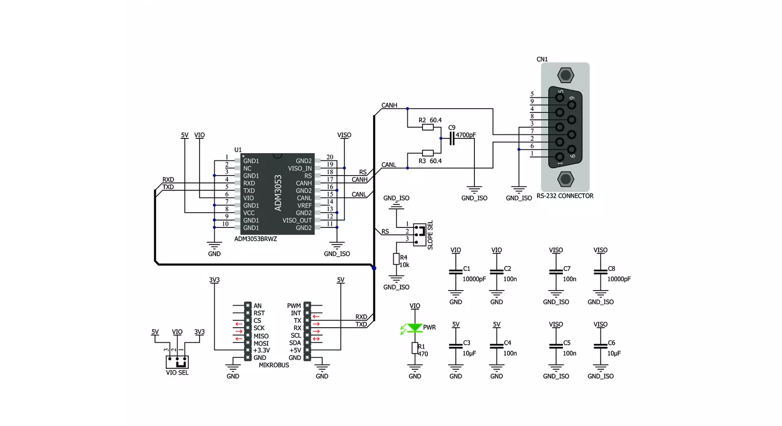
CAN Isolator Click is based on the ADM3053, a power isolated CAN transceiver with an integrated isolated DC-to-DC converter from Analog Devices. The click is designed to run on either 3.3V or 5V power supply. CAN Isolator Click communicates
with the target microcontroller over the UART interface. The ADM3053 is an isolated controller area network (CAN) physical layer transceiver with an integrated isolated DC-to-DC converter. The ADM3053 creates a fully isolated
interface between the CAN protocol controller and the physical layer bus. It is capable of running at data rates of up to 1Mbps.


Features overview
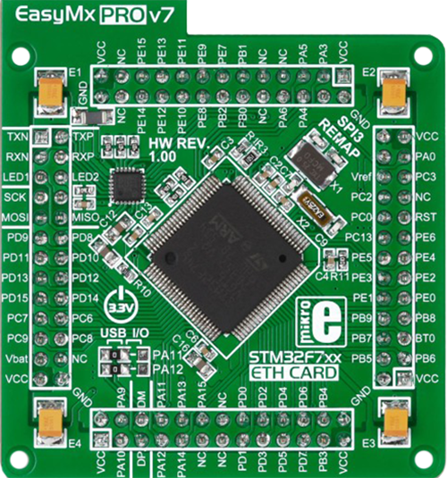
Development board
EasyMx PRO v7a for STM32 is the seventh generation of ARM development boards specially designed to develop embedded applications rapidly. It supports a wide range of 32-bit ARM microcontrollers from STMicroelectronics and a broad set of unique functions, such as the first-ever embedded debugger/programmer over USB-C. The development board is well organized and designed so that the end-user has all the necessary elements, such as switches, buttons, indicators, connectors, and others, in one place. With two different connectors for each port, EasyMx PRO v7afor STM32 allows you to connect accessory boards, sensors, and custom electronics more efficiently than ever. Each part of the EasyMx
PRO v7a for STM32 development board contains the components necessary for the most efficient operation of the same board. In addition to the advanced integrated CODEGRIP programmer/debugger module, which offers many valuable programming/debugging options and seamless integration with the Mikroe software environment, the board also includes a clean and regulated power supply block for the development board. It can use a wide range of external power sources, including an external 12V power supply, 7-23V AC or 9-32V DC via DC connector/screw terminals, and a power source via the USB Type-C (USB-C) connector. Communication options such as USB-UART, USB-HOST/DEVICE, CAN, and
Ethernet are also included, including the well-established mikroBUS™ standard, one display option for the TFT board line of products, and a standard TQFP socket for the seventh-generation MCU cards. This socket covers 32-bit ARM MCUs like STM32 Cortex-M3, -M7, and -M4 MCUs. EasyMx PRO v7afor STM32 is an integral part of the Mikroe ecosystem for rapid development. Natively supported by Mikroe software tools, it covers many aspects of prototyping and development thanks to a considerable number of different Click boards™ (over a thousand boards), the number of which is growing every day.

Microcontroller Overview
MCU Card / MCU
Type
7th Generation
Architecture
ARM Cortex-M4
MCU Memory (KB)
10
Silicon Vendor
STMicroelectronics
Pin count
100
RAM (Bytes)
192k
You complete me!
Accessories
DB9 Cable Female-to-Female (2m) cable is essential for establishing dependable serial data connections between devices. With its DB9 female connectors on both ends, this cable enables a seamless link between various equipment, such as computers, routers, switches, and other serial devices. Measuring 2 meters in length, it offers flexibility in arranging your setup without compromising data transmission quality. Crafted with precision, this cable ensures consistent and reliable data exchange, making it suitable for industrial applications, office environments, and home setups. Whether configuring networking equipment, accessing console ports, or utilizing serial peripherals, this cable's durable construction and robust connectors guarantee a stable connection. Simplify your data communication needs with the 2m DB9 female-to-female cable, an efficient solution designed to meet your serial connectivity requirements easily and efficiently.

Used MCU Pins
mikroBUS™ mapper
Take a closer look
Click board™ Schematic
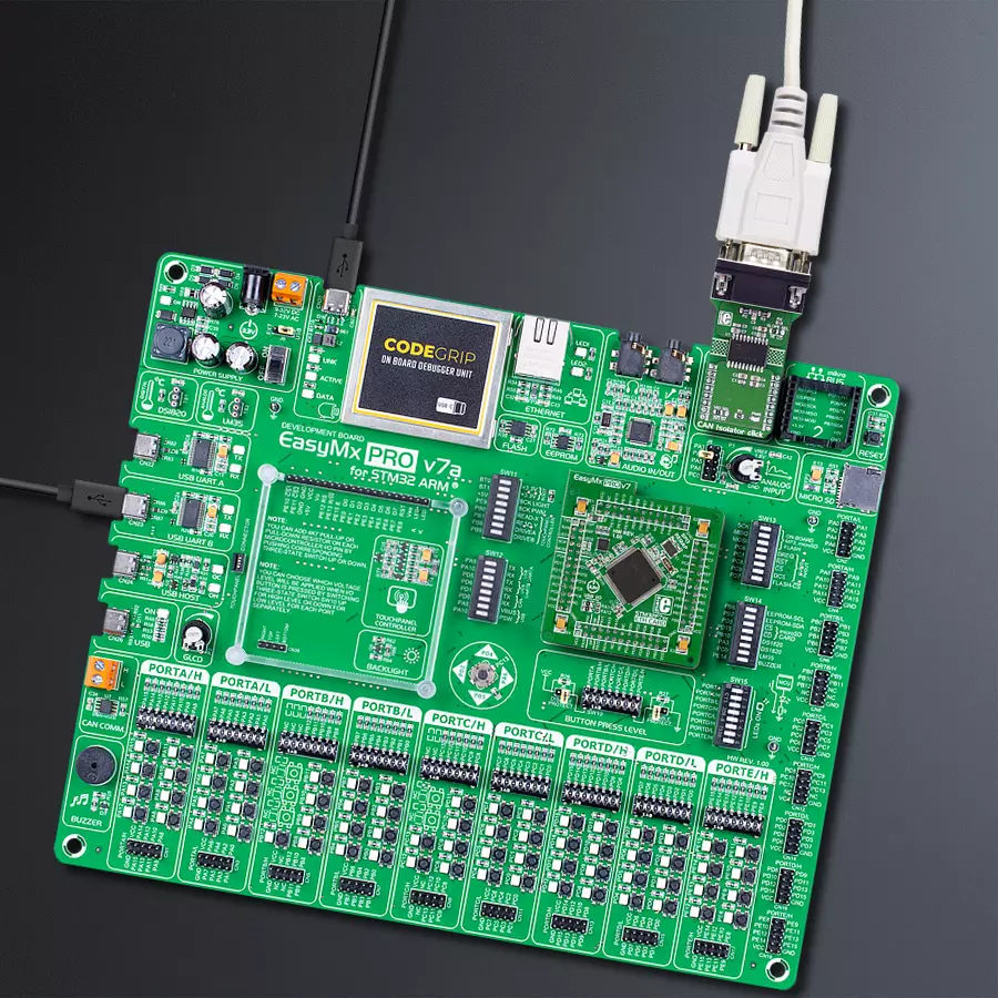
Step by step
Project assembly

Start by selecting your development board and Click board™. Begin with the EasyMx PRO v7a for STM32 as your development board.


Software Support
Library Description
This library contains API for CAN Isolator Click driver.
Key functions:
canisolator_generic_multi_write- Generic multi write functioncanisolator_generic_multi_read- Generic multi read functioncanisolator_generic_single_read- Generic single read functioncanisolator_generic_single_write- Generic single write function
Open Source
Code example
The complete application code and a ready-to-use project are available through the NECTO Studio Package Manager for direct installation in the NECTO Studio. The application code can also be found on the MIKROE GitHub account.
/*!
 * \file
 * \brief CanIsolator Click example
 *
 * # Description
 * This is a example which demonstrates the use of Can Isolator Click board.
 *
 * The demo application is composed of two sections :
 *
 * ## Application Init
 * Configuring Clicks and log objects.
 *
 * ## Application Task
 * Checks if new data byte has received in RX buffer ( ready for reading )
 * and if ready than reads one byte from RX buffer.
 * In the second case, the application task writes message data via UART.
 * Results are being sent to the Usart Terminal where you can track their changes.
 *
 * \author MikroE Team
 *
 */
// ------------------------------------------------------------------- INCLUDES

#include "board.h"
#include "log.h"
#include "canisolator.h"

// ------------------------------------------------------------------ VARIABLES

//#define DEMO_APP_RECEIVER
#define DEMO_APP_TRANSMITER

static canisolator_t canisolator;
static log_t logger;

static char demo_message[ 9 ] = { 'M', 'i', 'k', 'r', 'o', 'E', 13, 10, 0 };

// ------------------------------------------------------- ADDITIONAL FUNCTIONS


// ------------------------------------------------------ APPLICATION FUNCTIONS

void application_init ( void )
{
    log_cfg_t log_cfg;
    canisolator_cfg_t cfg;

    /**
     * Logger initialization.
     * Default baud rate: 115200
     * Default log level: LOG_LEVEL_DEBUG
     * @note If USB_UART_RX and USB_UART_TX
     * are defined as HAL_PIN_NC, you will
     * need to define them manually for log to work.
     * See @b LOG_MAP_USB_UART macro definition for detailed explanation.
     */
    LOG_MAP_USB_UART( log_cfg );
    log_init( &logger, &log_cfg );
    log_info( &logger, "---- Application Init ----" );

    //  Click initialization.

    canisolator_cfg_setup( &cfg );
    CANISOLATOR_MAP_MIKROBUS( cfg, MIKROBUS_1 );
    canisolator_init( &canisolator, &cfg );

    log_printf( &logger, "---------------------\r\n" );
    log_printf( &logger, " CAN Isolator  Click\r\n" );
    log_printf( &logger, "---------------------\r\n" );
    Delay_ms ( 100 );
}

void application_task ( void )
{
    char tmp;

#ifdef DEMO_APP_RECEIVER

    // RECEIVER - UART polling

    tmp =  canisolator_generic_single_read( &canisolator );
    log_printf( &logger, " %c ", tmp );

#endif
#ifdef DEMO_APP_TRANSMITER

    // TRANSMITER - TX each 2 sec

    uint8_t cnt;

    for ( cnt = 0; cnt < 9; cnt ++ )
    {
        canisolator_generic_single_write( &canisolator, demo_message[ cnt ] );
        Delay_ms ( 100 );
    }

    Delay_ms ( 1000 );
    Delay_ms ( 1000 );

#endif

}

int main ( void )
{
    /* Do not remove this line or clock might not be set correctly. */
    #ifdef PREINIT_SUPPORTED
    preinit();
    #endif

    application_init( );

    for ( ; ; )
    {
        application_task( );
    }

    return 0;
}


// ------------------------------------------------------------------------ END
Additional Support
Resources
Category:CAN


