Provide insights into balance and movement with ITG-3701 and STM32F407VGT6
Spin the future

Published Oct 05, 2023
Click board™
Gyro 5 Click
Dev. board
EasyMx PRO v7a for STM32
Compiler
NECTO Studio
MCU
STM32F407VGT6
Navigate the future of augmented reality and virtual environments with our gyroscope, delivering lifelike interactions and immersive simulations
A
A
Hardware Overview
How does it work?
Gyro 5 Click is based on the ITG-3701, a three-axis digital gyroscope sensor from TDK InvenSense. This device features factory calibrated scale factor, High cross-axis isolation via proprietary MEMS design and a precision clock with 1% drift from -40°C to 85°C, which results in a high level of integration, allowing very good linearity over temperature, and increased output stability when no motion. It also makes it resistant to shocks up to 10,000g, allowing it to be used for speeds up to 4000 dps. It supports signal conditioning including low-pass filtering, as well as the programmable interrupt. Typically, higher dps range results in lower sensitivity. Therefore, the ITG-3701 allows to dynamically select the full-scale range (FSR) value in several discrete steps: ±500, ±1000, ±2000 and ±2000 dps. This allows optimized performance for a given usage scenario. For example, if used in applications with faster angle rates such as sports equipment monitoring (golf club or tennis racket), a higher FSR might be required, at a cost of lower sensitivity. The MEMS output voltage is sampled by a high-accuracy 16-bit A/D converter, allowing the output in 2’s complement format. As mentioned above, different FS ranges have different sensitivity per
LSB. Therefore, raw output values of the sensor will have to be multiplied with the sensitivity to obtain the values in degrees per second (dps). These values can be obtained from the ITG-3701 datasheet, for every FS range, respectively. The ITG-3701 sensor feature an internal programmable low-pass filter, with user-selectable cutoff frequency. The output signal can be digitally selected and applied to an angular speed measurement, allowing the developer to reduce the noise or fine-tune the sensitivity within a desired bandwidth. The ITG-3701 device features a FIFO buffer, which in combination with a dedicated interrupt line, allows firmware optimizations while reducing the power consumption of the application as a result. The FIFO buffer has 32 slots, each 16-bit wide, used to store output values. The FIFO can lower the traffic on the serial bus interface, and reduce power consumption by allowing the system processor to burst read sensor data and then go into a low-power mode. A FIFO counter keeps track of how many bytes of valid data are contained in the FIFO. The FIFO register supports burst reads, while the interrupt function may be used to determine when new data is available. The interrupt pin is
routed to the mikroBUS™ INT pin (labeled as INT). This line is used to report one of the programmable FIFO events: watermark level is reached, FIFO buffer is empty, and there is an overrun event on the FIFO buffer (FIFO is full). The pin can also be used to report when there is a new data available at the output after the conversion period (data ready). To find out which event exactly has occurred, the host MCU should read the status of the respective flag bits from the INT_STATUS register. Gyro 5 click offers two communication interfaces. It can be used with either I2C or SPI. The onboard SMD jumpers labeled as COMM SEL allow switching between the two interfaces. Note that all the jumpers have to be positioned either I2C or to SPI position. When I2C interface is selected, an additional SMD jumper labeled as ADDR SEL becomes available, determining the least significant bit of the ITG-3701 slave I2C address. The Click board™ can operate with 3.3V MCUs only, it is set to work over the I2C by default, and it is already equipped with the pull-up resistors. It is ready to be used as soon as it is inserted into a mikroBUS™ socket of the development system.


Features overview
Development board
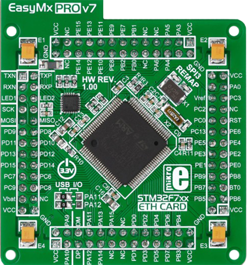
EasyMx PRO v7a for STM32 is the seventh generation of ARM development boards specially designed to develop embedded applications rapidly. It supports a wide range of 32-bit ARM microcontrollers from STMicroelectronics and a broad set of unique functions, such as the first-ever embedded debugger/programmer over USB-C. The development board is well organized and designed so that the end-user has all the necessary elements, such as switches, buttons, indicators, connectors, and others, in one place. With two different connectors for each port, EasyMx PRO v7afor STM32 allows you to connect accessory boards, sensors, and custom electronics more efficiently than ever. Each part of the EasyMx
PRO v7a for STM32 development board contains the components necessary for the most efficient operation of the same board. In addition to the advanced integrated CODEGRIP programmer/debugger module, which offers many valuable programming/debugging options and seamless integration with the Mikroe software environment, the board also includes a clean and regulated power supply block for the development board. It can use a wide range of external power sources, including an external 12V power supply, 7-23V AC or 9-32V DC via DC connector/screw terminals, and a power source via the USB Type-C (USB-C) connector. Communication options such as USB-UART, USB-HOST/DEVICE, CAN, and
Ethernet are also included, including the well-established mikroBUS™ standard, one display option for the TFT board line of products, and a standard TQFP socket for the seventh-generation MCU cards. This socket covers 32-bit ARM MCUs like STM32 Cortex-M3, -M7, and -M4 MCUs. EasyMx PRO v7afor STM32 is an integral part of the Mikroe ecosystem for rapid development. Natively supported by Mikroe software tools, it covers many aspects of prototyping and development thanks to a considerable number of different Click boards™ (over a thousand boards), the number of which is growing every day.

Microcontroller Overview
MCU Card / MCU
Type
7th Generation
Architecture
ARM Cortex-M4
MCU Memory (KB)
10
Silicon Vendor
STMicroelectronics
Pin count
100
RAM (Bytes)
192k
Used MCU Pins
mikroBUS™ mapper
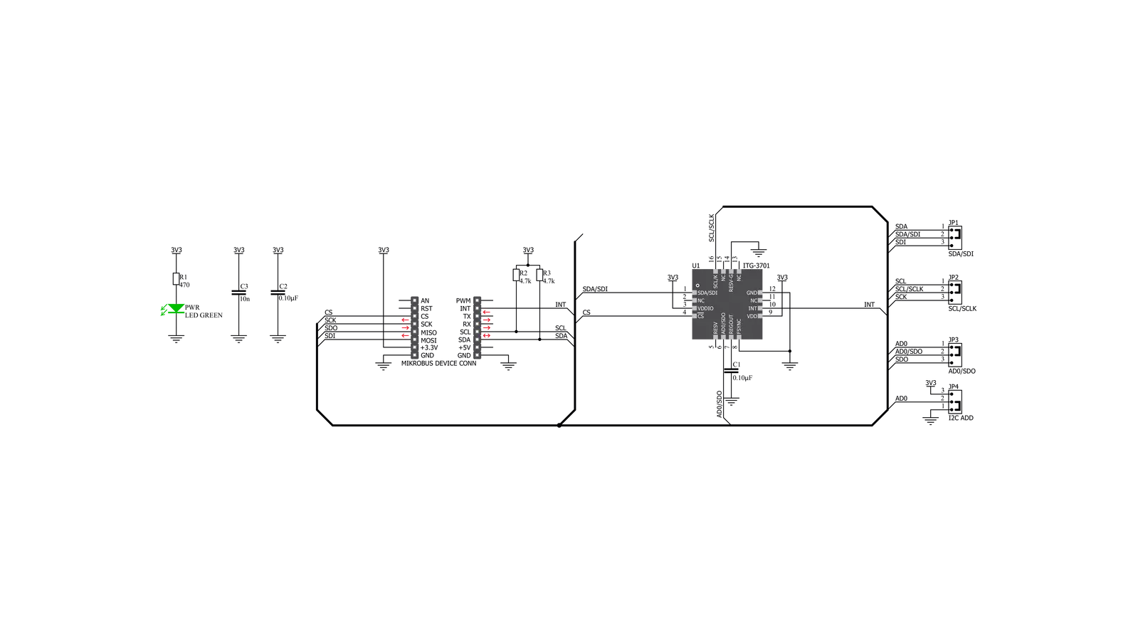
Take a closer look
Click board™ Schematic
Step by step
Project assembly

Start by selecting your development board and Click board™. Begin with the EasyMx PRO v7a for STM32 as your development board.


Track your results in real time
Application Output
1. Application Output - In Debug mode, the 'Application Output' window enables real-time data monitoring, offering direct insight into execution results. Ensure proper data display by configuring the environment correctly using the provided tutorial.

2. UART Terminal - Use the UART Terminal to monitor data transmission via a USB to UART converter, allowing direct communication between the Click board™ and your development system. Configure the baud rate and other serial settings according to your project's requirements to ensure proper functionality. For step-by-step setup instructions, refer to the provided tutorial.

3. Plot Output - The Plot feature offers a powerful way to visualize real-time sensor data, enabling trend analysis, debugging, and comparison of multiple data points. To set it up correctly, follow the provided tutorial, which includes a step-by-step example of using the Plot feature to display Click board™ readings. To use the Plot feature in your code, use the function: plot(*insert_graph_name*, variable_name);. This is a general format, and it is up to the user to replace 'insert_graph_name' with the actual graph name and 'variable_name' with the parameter to be displayed.

Software Support
Library Description
This library contains API for Gyro 5 Click driver.
Key functions:
gyro5_get_axes- Getting gyroscope axes valuesgyro5_get_temperature- Getting temperature valuegyro5_default_cfg- Click Default Configuration function
Open Source
Code example
The complete application code and a ready-to-use project are available through the NECTO Studio Package Manager for direct installation in the NECTO Studio. The application code can also be found on the MIKROE GitHub account.
/*!
 * \file
 * \brief Gyro5 Click example
 *
 * # Description
 * This application shows temperature and gyroscope axes values
 *
 * The demo application is composed of two sections :
 *
 * ## Application Init
 * Initializes GPIO pins, I2C and LOG modules.
 *
 * ## Application Task
 * Checks data ready INT, gets temperature and axes data and LOGs those values
 *
 * \author Luka Filipovic
 *
 */
// ------------------------------------------------------------------- INCLUDES

#include "board.h"
#include "log.h"
#include "gyro5.h"

// ------------------------------------------------------------------ VARIABLES

static gyro5_t gyro5;
static log_t logger;

uint8_t data_ready_flag;
float temperature_value;

float x_axis_value;
float y_axis_value;
float z_axis_value;

// ------------------------------------------------------ APPLICATION FUNCTIONS

void application_init ( void )
{
    log_cfg_t log_cfg;
    gyro5_cfg_t cfg;

    /**
     * Logger initialization.
     * Default baud rate: 115200
     * Default log level: LOG_LEVEL_DEBUG
     * @note If USB_UART_RX and USB_UART_TX
     * are defined as HAL_PIN_NC, you will
     * need to define them manually for log to work.
     * See @b LOG_MAP_USB_UART macro definition for detailed explanation.
     */
    LOG_MAP_USB_UART( log_cfg );
    log_init( &logger, &log_cfg );
    log_info( &logger, "---- Application Init ----" );

    //  Click initialization.

    gyro5_cfg_setup( &cfg );
    GYRO5_MAP_MIKROBUS( cfg, MIKROBUS_1 );
    gyro5_init( &gyro5, &cfg );
    gyro5_default_cfg ( &gyro5 );
    Delay_ms ( 1000 );

    log_printf( &logger, "      Gyro 5 Click\r\n" );
    log_printf( &logger, "-----------------------\r\n" );
}

void application_task ( void )
{
    //  Task implementation.

    data_ready_flag = gyro5_int_status( &gyro5, GYRO5_INT_DATA_RDY );

    if ( data_ready_flag == GYRO5_STATUS_INT_DATA_RDY )
    {
        gyro5_get_temperature( &gyro5, &temperature_value );
        Delay_ms ( 10 );
        gyro5_get_axes(  &gyro5, &x_axis_value, &y_axis_value, &z_axis_value );
        Delay_ms ( 10 );
        log_printf( &logger, " Temperature = %.2f C\r\n", temperature_value );
        log_printf( &logger, " X axis = %.2f \r\n", x_axis_value );
        log_printf( &logger, " Y axis = %.2f \r\n", y_axis_value );
        log_printf( &logger, " Z axis = %.2f \r\n", z_axis_value );
        log_printf( &logger, "------------------------\r\n" );
        Delay_ms ( 1000 );
        Delay_ms ( 1000 );
    }
}

int main ( void )
{
    /* Do not remove this line or clock might not be set correctly. */
    #ifdef PREINIT_SUPPORTED
    preinit();
    #endif

    application_init( );

    for ( ; ; )
    {
        application_task( );
    }

    return 0;
}


// ------------------------------------------------------------------------ END


